
TOSHIBA TOSBERT S11 series frequency converter
TOSHIBA TOSBERT S11 series frequency converter
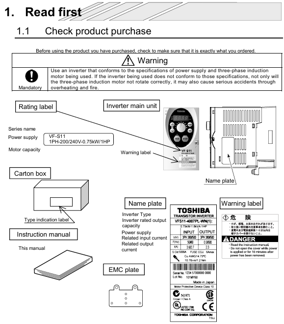
Document Overview and Basic Equipment Information
Document positioning: The official user manual for Toshiba TOSBERT S11 series frequency converters is designed for electrical engineers and maintenance personnel, covering the entire process of equipment installation, wiring, operation, parameter setting, fault handling, and maintenance, highlighting the characteristics of "compact" and "high compatibility".
Equipment specifications and models:
Voltage level, power range, input type, applicable scenarios, typical models
200V level 0.1-1.5kW single-phase small equipment (laboratory instruments, household equipment) S11-2001S (0.1kW), S11-2015S (1.5kW)
200V level 2.2-15kW three-phase small and medium-sized motors (conveyors, packaging machines) S11-2002H (2.2kW), S11-2015H (15kW)
400V level 0.4-30kW three-phase medium and large equipment (fans, pumps, small machine tools) S11-4004H (0.4kW), S11-4030H (30kW)
Model coding rules: Taking "S11-4015H-C" as an example, the meanings of each part are:
S11: Series Code (TOSBERT S11 Series)
4: Voltage level (2=200V level, 4=400V level)
015: Capacity (15kW, 0.1kW model standard 001)
H: Basic configuration (H=standard, S=simple, L=low noise)
C: Optional functions (C=built-in communication module, F=built-in braking unit)
Core technical features:
Ultra compact design: The volume is reduced by 30% compared to the previous generation S7 series, and the size of the 0.4kW model is only 75 × 130 × 100mm, saving control cabinet space.
High protection and compatibility: basic model IP20, optional IP40 (anti solid foreign object+anti splash water); Compliant with NEMA ISO14001 Part 31, fully compatible with variable frequency drive, suitable for various asynchronous motors.
Control accuracy: In sensorless vector (SVC) mode, the output is 150% of the rated torque at 0.5Hz, with a speed accuracy of ± 0.1%, meeting the high-precision requirements of small and medium power.
Installation specifications and environmental requirements
1. Installation method (segmented by power)
Power Range Installation Method Installation Requirements Applicable Scenarios
≤ 0.4kW (200V single-phase/400V three-phase) DIN rail installation compatible with 35mm standard DIN rail, rail length ≥ inverter width, installation surface flatness ≤ 0.5mm Small control cabinet, distributed installation
≥ 0.75kW (200V three-phase/400V three-phase) vertical wall mounted installation fixed on a metal backplate with a thickness of ≥ 1.5mm, backplate grounded (≤ 10 Ω), screw torque 2.5-4.0N · m, medium-sized control cabinet, centralized installation
All models (IP40 configuration) require a larger ventilation gap (≥ 5cm on both sides) to be reserved for independent installation. It is prohibited to be in close proximity to heating equipment (such as contactors) in dusty/humid environments (such as food processing workshops)
2. Ventilation gaps and environmental restrictions
Ventilation gap (Figure 2-1):
Protection level: Top gap, bottom gap, left and right gap, back gap
IP20 ≥5cm ≥5cm ≥3cm ≥5cm
IP40 ≥8cm ≥8cm ≥5cm ≥8cm
Environmental restrictions:
Temperature: IP20 model -10 ℃~40 ℃, IP40 model -10 ℃~50 ℃; For every 1 ℃ increase in overheating, the rated power decreases by 1% (up to a maximum of 50 ℃).
Humidity: ≤ 90% RH, no condensation (condensation environment requires IP40+anti condensation heater).
Altitude: ≤ 1000m (over 1000m, power reduction of 1% per 100m, up to 3000m).
Vibration: Acceleration ≤ 0.5G (10-50Hz), amplitude ≤ 0.08mm (50-150Hz), exceeding the range requires adding or removing vibration pads.
3. Transportation and Storage
Transportation: Fill the packaging box with cushioning material, do not invert/flip it over, and avoid collision (to prevent damage to internal capacitors and modules).
Storage: Temperature -20 ℃~60 ℃, humidity ≤ 60% RH; long-term storage (≥ 6 months). Power on for 30 minutes every 6 months (no load) to activate the capacitor.
Wiring specifications and hardware configuration
1. Main circuit wiring (with differences in power segments)
(1) 200V level (single-phase/three-phase) main circuit terminal
Terminal identification function wiring requirements cable specifications (copper core)
L/N (single-phase), L1/L2/L3 (three-phase) power input series MCCB (capacity=1.2-1.5 × rated current), prohibit connecting compensating capacitors 0.1-0.75kW: 0.75mm ²; 1.5-15kW:1.5-4mm²
U/V/W motor output corresponds to motor U/V/W, reverse exchange any two phases; Cable length ≤ 30m (over 30m with output reactor) consistent with input cable
PE protective grounding Class 3 grounding (≤ 10 Ω), yellow green dual color wire, prohibited from sharing ≥ 1/2 of input cable with neutral wire, minimum 0.75mm ²
B1/B2 brake resistor connection ≤ 7.5kW can be connected to a built-in resistor; 7.5kW requires an external connection of ≥ 1.5mm ² (optional according to braking power)
(2) 400V level main circuit terminal
Power ≤ 7.5kW: The terminal configuration is the same as 200V three-phase, with the addition of "input filter terminal (F1/F2)" and optional EMC filter.
Power ≥ 11kW: divided into "main power input (L1/L2/L3)" and "reactor input (L1R/L2S/L3T)", forced external input reactor (harmonic suppression, protection module).
- OMRON
- ABB
- General Electric
- EMERSON
- Honeywell
- HIMA
- ALSTOM
- Rolls-Royce
- MOTOROLA
- Rockwell
- Siemens
- Woodward
- YOKOGAWA
- FOXBORO
- KOLLMORGEN
- MOOG
- KB
- YAMAHA
- BENDER
- TEKTRONIX
- Westinghouse
- AMAT
- AB
- XYCOM
- Yaskawa
- B&R
- Schneider
- KONGSBERG
- NI
- WATLOW
- ProSoft
- SEW
- ADVANCED
- Reliance
- TRICONEX
- METSO
- MAN
- Advantest
- STUDER
- DANAHER MOTION
- Bently
- Galil
- EATON
- MOLEX
- DEIF
- B&W
- ZYGO
- Aerotech
- DANFOSS
- Beijer
- Moxa
- Rexroth
- Johnson
- WAGO
- TOSHIBA
- BMCM
- SMC
- HITACHI
- HIRSCHMANN
- Application field
- XP POWER
- CTI
- TRICON
- STOBER
- Thinklogical
- Horner Automation
- Meggitt
- Fanuc
- Baldor
- SHINKAWA
- Other Brands
- UniOP
- KUKA
- Iba
- Beckhoff
-
 Basler BE1-25 Time Overcurrent Relay M1FA6PA4S0F
 -
 Basler SR4A2B05B3E Static Voltage Regulator
 -
 Basler DECS-200-2L Digital Excitation Control
 -
 Basler BE303280001 Control Transformer
 -
 Basler 9262103004 Voltage Regulator Board For Basler DECS-400
 -
 Basler ICRM-7 Inrush Current Reduction Module
 -
 Basler BE1-32R Power Relay
 -
 BASLER ELECTRIC KR4F VOLTAGE REGULATOR 9042600100 600V 50/60Hz
 -
 Basler 9222600101 Power Module
 -
 Basler SR8A-2B15B3A Static Voltage Regulator
 -
 BASLER BE1-87G G1E A1L A0N1P Generator Differential Relay w/ Reactor 9170818100
 -
Basler 9284900101 DECS Power Module
-
 Basler PRS250 Veri-Sync Relay
 -
 Basler BE 12296 001 Transformer
 -
 Basler 905970-104 Rev.M Voltage Regulator
 -
Basler BE1-87T Transformer Differential Relay
-
 Basler SR8A-2B15B3A Static Voltage Regulator
 -
 Basler SR32A2B05B3E Static Voltage Regulator
 -
 Basler SR4A-2B16B3A Static Voltage Regulator
 -
 Basler SR32A-2B13B3E Static Voltage Regulator
 -
 Basler KR4F Voltage Regulator 9042600100
 -
 Basler SSR 32-12 Static Voltage Regulator 400Hz
 -
 Basler CBS 212A Current Boost System
 -
 Basler MVC236 Manual Control Module
 -
Basler UFOV Protective Module 9040000100
-
 Basler SSR 125-12 Static Voltage Regulator
 -
 Basler SR4A2B10A3E Static Voltage Regulator
 -
 Basler BE1-25 Solid State Time Overcurrent Relay
 -
 Basler MVC 232 Manual Voltage Control Module
 -
Basler PRS 250 Veri-Sync Relay
-
 Basler UFOV 260A Under Frequency Over Voltage Relay
 -
 Basler RUL2098-10GC Load Relay
 -
 Basler 9 1049 04 100 PC Board
 -
Basler 125-12 Static Voltage Regulator
-
Basler PRS 250 Veri-Sync Relay
-
Basler 9185900102 SSR 125-12 Regulator
-
Basler BE12819001 Reactor
-
 Teradyne 535-100-00 Power Supply
 -
 Basler BE1-67 Directional OC Relay
 -
 Basler PRP110 Reverse Power Relay
 -
 Basler BE30631001 Isolation Transformer
 -
 Basler DECS-200-2L Digital Excitation Control
 -
 Basler BE1-47N Voltage Phase Sequence Relay
 -
 Basler AEC63-7 Analog Excitation Controller 220-277V
 -
Basler BE1-50/51B-107 Overcurrent Relay
-
 Basler Electric BE1‑32R BE1‑E1P‑BON0F Protective Relay
 -
Basler BE1-25 Solid State Time Overcurrent Relay M1EA6PA5S1F
-
 Basler MVC 232 Manual Voltage Control Module 90 37000 103 60VAC 55VDC
 -
Basler RAL6144-16GM Racer GigE Line Scan Camera
-
Basler SSR 63-12 Static Voltage Regulator
-
 Basler BE1-51A Overcurrent Relay
 -
Basler BE1-87T Solid State Protective Relay
-
Basler SR4A2B01B3A Static Voltage Regulator
-
 Basler SSR 32-12 Static Voltage Regulator
 -
 Basler TRR00696 Transformer 1KVA 115V
 -
 Basler DECS-100-B15 AVR Replacement
 -
Basler BE1-27 Under-Voltage Relay
-
 Basler ACA2000-50GM Interface Module
 -
 Basler AEC63-7 Analog Excitation Controller
 -
Basler PRS 250 Veri-Sync Relay
-
 Basler SR4A-2B15B3A Static Voltage Regulator
 -
Basler BE1-32R Power Relay
-
Basler SR8A-2B06B3E Static Voltage Regulator
-
Basler BE1-81 O/U Frequency Relay
-
 Basler BE1-51A-K2E-W6M-B1N0F Overcurrent Relay
 -
Basler BE1-851 Overcurrent Relay G3A1S1 – 48-125V AC/DC
-
 Basler BEI-51 Overcurrent Relay – NSN 5945-01-293-2363
 -
Basler Electric L301KC Protective Relay – L301KC
-
 Basler DECS-100-B15 Automatic Voltage Regulator – Generator AVR
 -
Basler SR4A-2B15B3A Static Voltage Regulator – SR4A2B15B3A
-
Basler UF 312 Under Frequency Protective Module – 9094700100
-
Basler Electric MVC 232 Manual Control Module – 60VAC 55VDC 20A
-
Basler PRS 250 Veri-Sync Relay – Generator Synchronizing Relay
-
 Basler DECS-100-A05 Digital Regulator Review
 -
 Basler AEM-2020 Analog Expansion Module Specs
 -
 Basler DECS-100-B15 Digital Excitation Specs
 -
Basler Electric 9125600106 Regulator Component
-
Basler BE1-51A-K1E-W6M-B1N0F Overcurrent Relay
-
 Basler MVC-301 MVC 300 Excitation Controller
 -
Basler SSR 32-12 Static Voltage Regulator
-
Basler 9-2849-00-101 Control Module
-
Basler BE1-51A Overcurrent Relay
-
 Basler BE1-51/27R Overcurrent Relay
 -
 Basler BE1-51 Overcurrent Relay
 -
 Basler SR8A-2B15B3A Static Voltage Regulator
 -
 Basler BE32965001 Transformer and Timer Board
 -
 Basler 9174700100 EL200-7 Excitation Limiter
 -
 Basler BE2000E AVR Voltage Regulator
 -
Basler BE1-87G Differential Relay
-
 Basler BE21834001 Generator Control Module
 -
Basler DECS-100-B15 AVR
-
 Basler D90 96801 100 PCB Card
 -
 Basler XR2002F Voltage Regulator (110 VAC, 48-480 Hz)
 -
 Basler SR8A-2B14B3A Regulator
 -
 Basler 9561500100 Module
 -
 Basler DECS-400 BE1-11 System
 -
 Basler DECS-100-B15 Excitation Control
 -
Basler SCP 210 Frequency Controller
-
Basler SR4A-2B15B3A Static Voltage Regulator
-
Basler BE1-32R Power Relay
-
 Basler PIA2400-17GM Power Interface Adapter
 -
 Basler MVC 232 Manual Voltage Control Module
 -
Basler SSR 32-12 Static Voltage Regulator
-
Basler 5MW AVR Generator Voltage Regulator
-
 Basler VR63-4B Voltage Regulator
 -
Basler DECS-100-A05 AVR for Engine Generator
-
Basler DECS-100-B15 Automatic Voltage Regulator
-
Basler BE1-32R Directional Power Relay
-
Basler BE1-87B Differential Relay
-
 Basler UFOV 260A Protective Module
 -
 Basler 9-2614-02-100 PCB Rev M
 -
Basler DECS-100-B15 Digital AVR
-
 Basler 9284900103 PS DECS-400N
 -
 Basler D4N3H1U Intertie Protection
 -
 Basler DECS-100-B15 A15 AVR
 -
 Basler KR4F Voltage Regulator
 -
 Basler BE26434 T14 Transformer
 -
 Basler SR8A-2B15B3A Regulator
 -
 Westinghouse 774B472A12 AR Relay
 -
Basler DECS-100-B15 AVR
-
Basler XR2002F Regulator 110V
-
Basler SR125-E Static Regulator
-
Basler SSR 125-12 Regulator
-
Basler MOC2599 Motor Pot
-
 Basler BE1-DFPR Feeder Relay
 -
 Basler CBS 305 Current Boost
 -
Basler BE1-25 AutoSync
-
Basler MVC 300 Voltage Control


