
SIEMENS SIMOTICS L-1FN3 Linear Motor Operating Instructions
SIEMENS SIMOTICS L-1FN3 Linear Motor Operating Instructions
Overview
SIMOTICS L-1FN3 series permanent magnet synchronous linear motor operation guide, covering the entire life cycle process from receiving, installation to scrapping. The core information includes: the motor is a modular structure (including primary components, secondary components, and optional precision coolers/secondary coolers), with protection level of IP65 for primary components, minimum IP23 after installation, suitable medium temperature of * * -20... 220 ° C * * (special sealing letter needs to be replaced for low temperature), cooling method is water cooling (maximum pressure of cooling circuit is 10 bar), and needs to be used with SAX. electric actuators or SKD./SKB./SKC. electric hydraulic actuators; The manual emphasizes the safety risks of strong magnetic fields (the suction force of the secondary component permanent magnet can reach several kN, and those wearing pacemakers need to maintain a distance of ≥ 500mm), electrical connection specifications (must comply with SELV/PELV standards, and the shielding layer must be reliably grounded), and safe operation throughout the entire process. At the same time, it provides detailed guidance on mechanical installation dimensions, fault handling, maintenance, and waste disposal (secondary components need to be demagnetized at 300 ° C or above) to ensure the safe and stable operation of the motor.
Product Technical Characteristics
1. Basic parameter table
Parameter category specific specifications
Motor type: Permanent magnet synchronous linear motor
Modular structural form (primary components: including 3-phase winding+main cooler; secondary components: permanent magnet+steel base; optional precision cooler/secondary cooler)
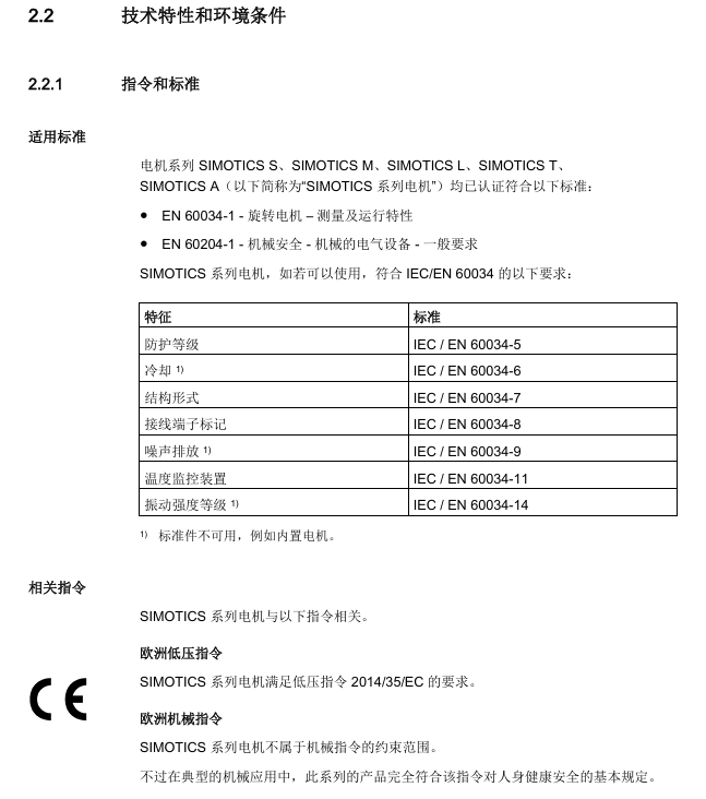
Protection level for primary components: IP65 (compliant with DIN EN 60034-5); Motor after installation: minimum IP23 (determined by machine design)
Cooling method: Water cooling (maximum pressure of cooling circuit is 10 bar, interface is G1/8 pipe thread, in accordance with DIN ISO 228-1)
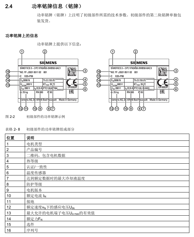
Thermal protection primary component with built-in 1 PTC thermistor (response threshold+120 ° C, compliant with DIN 44081/44082, Temp-S circuit)
Temperature monitoring Temp-F circuit (1FN3xxx-xxxx-xxx1 with KTY84 sensor, 1FN3xxx-xxxx-xxx3 with Pt1000 sensor)
Insulation Class Thermal Class 155 (F Class, compliant with EN 60034-1)
Electrical interface 1FN3050: Fixed cable (with/without connector); 1FN3100-1FN3900: Integrated connector+cover plate
2. Environmental and adaptation requirements
Temperature range:
Conventional: -5... 220 ° C; Low temperature: -20... 150 ° C (special sealing letter needs to be replaced: DN15... 50 is 428488060, DN65... 150 is 467956290)
Storage/transportation temperature: -5... 40 ° C (condensation and freezing are not allowed)
Rating reduction factor: When the installation height is greater than 2000m, the voltage needs to be reduced (such as 0.877 for 3000m and 0.656 for 5000m)
Adaptive actuator: It needs to be selected according to the driving force and stroke, as shown in the following table:
Applicable scenarios for actuator series driving force stroke
SAX. 800N 20mm DN ≤ 50 motor, light load
SKD. 1000N 20mm DN ≤ 50 motor, high load
SKB. 2800N 20mm DN ≥ 65 motor
SKC. 2800N 40mm DN ≥ 65 motor, large stroke requirement
Core safety requirements
1. Strong magnetic field safety (highest priority)
Risk point: The secondary component contains permanent magnets, and there is still a strong magnetic field in the power-off state. The suction force can reach several kN (equivalent to squeezing hundreds of kg of heavy objects), and the magnetic field strength can reach 3mT at a distance of 150mm (in accordance with Directive 2013/35/EU)
Safety measures:
Individuals wearing pacemakers/insulin pumps must maintain a distance of ≥ 500mm;
The installation of secondary components requires at least 2 people to work, wear gloves, prepare 3kg non-magnetic hammers and 10 ° -15 ° hardwood wedges (anti extrusion rescue);
Only remove the packaging of secondary components before installation, and it is forbidden to remove multiple packages at the same time. Do not place them side by side when they are not fixed;
It is prohibited to bring magnetic items (watches, steel tools) into the secondary component sensing area.
2. Electrical safety
Power requirements: Only allow connection to SELV (safe low voltage) or PELV (protective low voltage) power supply;
Induced voltage risk: When the primary and secondary components move relative to each other, the cable interface will generate induced voltage, which needs to be operated after power-off. It is forbidden to touch uninsulated interfaces;
Grounding and shielding:
Equipment with protection level I must be reliably grounded (to prevent contact voltage);
At least one side of the cable shielding layer is grounded through the grounding shell, and unused core wires need to be insulated or grounded;
The shielding layer of the power cable needs to be connected to the power module over a large area, and the protective grounding wire (PE) should be directly connected to the power module to prevent high discharge current from damaging the equipment.
3. Safe operation
Cooling system: No operation without cooling is allowed (overheating can cause the cooling water to vaporize and burst the pipes). The cooling circuit can only be connected after the motor has cooled down;
High temperature protection: The surface temperature of the motor during operation may exceed 100 ° C, and a "Hot Surface Warning" label should be affixed. During maintenance, it should be cooled down or protective gloves should be worn;
Unexpected operation: During debugging, it is necessary to limit the current and speed, ensure smooth travel, and keep personnel away from the operating/squeezing area.
Full process operation guide
1. Preparation for use (transportation and storage)
Transportation requirements:
Shipping/Highway: No additional magnetic field protection required;
Air freight: In accordance with IATA regulations, two secondary components must be stacked in opposite directions (offset<1cm), otherwise they must be transported as dangerous goods (magnetic field>0.418A/m at a distance of 2.1m);
Lifting: Primary components require lifting eye bolts (in accordance with DIN 580), with a horizontal lifting angle of ≥ 50 ° and a center of gravity perpendicular to the hook.
Storage requirements:
Environment: 1K3 level (temperature -5... 40 ° C, humidity 5% -85%, no condensation/vibration);
Duration: Up to 2 years, exposed parts without anti-corrosion agents need to be coated with Tectyl, and the cooling system needs to be emptied and blown with dry compressed air.
2. Mechanical installation
Fixed specifications:
Screw: Grade 10.9 brand new screw, tightening torque must meet the standards (M5=7.6Nm, M6=13.2Nm, M8=31.8Nm);
Surface: The fixed surface needs to be free of oil/grease/paint, with a surface roughness Rz of 10-40 μ m;
Screw in depth: It must comply with the minimum (e.g. 1.8 × d for St 37 material) and maximum limit (calculated by the machine tool manufacturer).
Installation steps:
Check the installation dimensions (installation dimension error of ± 0.3mm for different configurations of heavy-duty/long-term motors);
Clean the installation surface and install secondary components (tighten the screws in the prescribed order, with all "N" markings facing the same direction);
Install primary components (note to align with the "N" mark on the secondary components, and ensure that the fixing screws are screwed in to the correct depth);
Inspection: The slider needs to move flexibly (force fluctuations caused by tooth groove force are normal), and the air gap (0.5mm film with cover plate and 1.0mm film without cover plate, which should be able to move easily).
3. Connection (cooling and electrical)
Cooling circuit connection:
Material: Brass/stainless steel is recommended for the coolant interface, and the hose should be resistant to coolant (Festo/Rectus brand is recommended);
Circuit: It is recommended to have an independent circuit, and ensure that the inlet temperature of each primary component is consistent when connected in parallel. Flexible hoses should be used for connection (to prevent rigid connection seal failure);
Coolant: Water containing anti-corrosion agent (chloride/sulfate<100mg/l, pH=6.5-9.5), recommended 25% -30% ethylene glycol mixture (freezing point ≤ -5 ° C).
Electrical connection:
Cable specifications: 4-core power cable (core wire cross-section ≥ 2.5mm ², 2.5mm ² corresponds to maximum rated current of 21A), 4-core signal cable (cross-section 0.5mm ²);
Pin layout: The power interface is U/V/W/PE, and the temperature sensor interface needs to distinguish between PTC (Temp-S) and KTY84/Pt1000 (Temp-F). The core wire color needs to match (such as - KTY/Pt1000 for white and+KTY/Pt1000 for black);
Shielding treatment: Signal/power cables need to be wired separately, and the shielding layer should be grounded extensively (using clamps/clamps).
4. Debugging
Prerequisite: Complete mechanical installation, electrical/cooling connections, and have drive system documentation;
Key steps:
Checklist confirmation (general: complete components/complete documentation; mechanical: smooth travel/compliant air gap; electrical: correct grounding/shielding);
Insulation resistance test: Test with 1000V DC for 60 seconds, insulation resistance ≥ 10M Ω (between winding and PE, temperature sensor and PE);
Cooling system inspection: Ensure that the coolant meets the requirements, the circuit is leak free, and the pressure is ≤ 10 bar;
Trial operation: Limit current and speed, check commutation (phase sequence U-V-W is positive direction), monitor temperature sensor signal.
5. Operation and maintenance
Operation monitoring: It is necessary to monitor abnormalities (such as noise, heat, current rise, vibration), and immediately stop the machine for troubleshooting (see the table below for fault codes and handling);
Fault Handling Table:
Possible causes (code) of the fault phenomenon and remedial measures
Motor lock A (overload), B (phase loss) to reduce load, check frequency converter and feeder line
Abnormal noise during operation D (reversing fault), K (foreign object) detection of reversing angle, cleaning of air gap foreign objects
Abnormal no-load heating F (cooling not connected), G (insufficient water volume), connect cooling, check cooling water volume/inflow temperature
Slow shaft response E (winding short circuit), L (poor alignment), check winding resistance, and re align machine guide rail
Maintenance requirements: There is no regular maintenance cycle, and the following situations require maintenance: foreign objects around the motor, machine abnormalities (visual/auditory), decreased positioning accuracy, and increased current; During maintenance, power off and cool down for 30 minutes, clean the air gap chips/dust, and check the cable shielding layer.
6. Scrapping and waste disposal
Dismantling steps: In reverse order of installation, power off and discharge first → cool for 30 minutes → disconnect cooling → clamp cable → drain coolant → remove primary components → remove secondary components;
Waste disposal:
Secondary components: Professional enterprises are required to use a furnace with a temperature of ≥ 300 ° C to demagnetize for at least 30 minutes, collect and treat exhaust gas;
Material classification: electronic waste (encoder/winding/cable), iron waste (iron core), aluminum, insulation materials;
Packaging: Recyclable materials (PE-HD/PE-LD/PP/PS) recycling, wood is combustible.
Appendix and Support
Manufacturer recommendations: corrosion inhibitors (Tyfocor, Antifrogen N), cooling connectors (Rectus), plastic hoses (Festo/Rectus), distance film (SAHLBERG);
Abbreviations: Temp-S (over temperature cut-off monitoring circuit), Temp-F (temperature observation circuit), HSB (Hall sensor box), PE (protective grounding);
Additional guidance: Installation size of Hall sensor box (fixed position and spacing for different motor models, such as 35mm distance between HSB and primary components of 1FN3050-150 motor).
- OMRON
- ABB
- General Electric
- EMERSON
- Honeywell
- HIMA
- ALSTOM
- Rolls-Royce
- MOTOROLA
- Rockwell
- Siemens
- Woodward
- YOKOGAWA
- FOXBORO
- KOLLMORGEN
- MOOG
- KB
- YAMAHA
- BENDER
- TEKTRONIX
- Westinghouse
- AMAT
- AB
- XYCOM
- Yaskawa
- B&R
- Schneider
- KONGSBERG
- NI
- WATLOW
- ProSoft
- SEW
- ADVANCED
- Reliance
- TRICONEX
- METSO
- MAN
- Advantest
- STUDER
- DANAHER MOTION
- Bently
- Galil
- EATON
- MOLEX
- DEIF
- B&W
- ZYGO
- Aerotech
- DANFOSS
- Beijer
- Moxa
- Rexroth
- Johnson
- WAGO
- TOSHIBA
- BMCM
- SMC
- HITACHI
- HIRSCHMANN
- Application field
- XP POWER
- CTI
- TRICON
- STOBER
- Thinklogical
- Horner Automation
- Meggitt
- Fanuc
- Baldor
- SHINKAWA
- Other Brands
- UniOP
- KUKA
- Iba
- Beckhoff
-
 OMRON CJ1W-MD261 Mixed I/O Module
 -
 Omron NJ301-1100 PLC CPU eCat EIP Specs
 -
 Omron F500-C15-ETN Vision System PLC Module
 -
 Modicon M241-24IO TM/T2UK PLC with Ethernet
 -
 SIXNET YS-800-001 RTU PLC Module
 -
 BEMAC UST-202-D Interface Board 1307D V08B2
 -
 Yaskawa JANCD-MMOIC-02 Drive Circuit Board
 -
 ABB 3BSE005028R1 SDCS-COM-1 Comm Board
 -
 Omron 3G3MX2-A4110 A4150 Inverter Drives Specs
 -
 KEYENCE CA-E100 PLC Module
 -
 GE IC693ALG223-GB Analog Input Module Specs
 -
 ABB BAILEY IMMFP01 Multi Function Processor System
 -
 SIEMENS 6FC5372 0AA00 0AA1 NCU 7202 Controller
 -
Modicon TM241CE4 40I O Transistor Programmable Controller
-
 SIEMENS 6ES7 315 2EH13 0AB0 CPU 3152 PN DP
 -
 NORIS A1 91 PCB Card Rack Module System
 -
 SIEMENS 6ES7 313 5BE01 0AB0 Compact CPU
 -
 SCHNEIDER ELECTRIC S144B MICROLOGIC 60A Trip Unit
 -
 CNI PLC269 v3 Control Module Board Rev H
 -
ABB BAILEY IIMCP02 Processor Module
-
 OMRON NT20S ST121 EV3 Operator Interface Terminal
 -
 OMRON NS-CA001 Video Input Unit
 -
 GE Fanuc IC695CHS012 RX3i Backplane
 -
 Allen Bradley 2711E-K14C6 PanelView 1400e Terminal
 -
 Siemens Sinamics CCB 10000432.71 Power Cell
 -
 Siemens 6SL3210-1SE21-8UA0 Power Module PM340
 -
 Yaskawa CIMR-F7A20P4 AC Drive
 -
 Beckhoff EP1918-0002 EtherCAT Box I/O Module
 -
 OMRON CQM1-TC001 Temperature Control Module
 -
 GE Fanuc SGHA36AT0400 Industrial Contactor
 -
 OMRON NJ501-1500 PLC Machine Automation Controller
 -
 Mitsubishi MAZAK QX084 Power Supply MELDAS 500 CNC
 -
 B&R 0AC808.9 PLC Automation Module
 -
 OMRON CP1H-XA40DT1-D PLC Module
 -
 G&W Electric PLC15 5111 011 15kV Capnut Assembly
 -
 GE DS200SLCCG3AGH PCB Circuit Board
 -
 Siemens SINUMERIK 6FC3981-4FD PLC Extension
 -
 OMRON F300-DC I/O Image Processing Unit
 -
 FANUC A06B-0314-B002 AC Servo Motor
 -
 GC-S84 Programmable Controller Logic Module
 -
 PASABAN MONTELEC MTC3001-DC Drive Control PLC
 -
 Allen Bradley 100E460EJ11 Auxiliary Contactor
 -
 Bosch Rexroth 1070075337-101 Card Parameters
 -
 HMS Anybus AB7646-F Gateway Specifications
 -
 Bosch 062633-303401 CNC Servo PLC Card
 -
 TI 500-5023 Series PLC Power Supply
 -
 Siemens C98043-A7002-L1-12 Circuit Board
 -
 Omron E5CC-RX3A5M-000 Controller
 -
 CN-8032-L Profinet Network Adapter Module
 -
 Siemens 3TK2804-0BB4 Safety Relay Details
 -
 Toledo TTLM-2-1M I/O Load Module
 -
 NORIS A1-91 PLC Rack Board Specifications
 -
 Mitsubishi A3ACPUR21 MELSEC PLC CPU Module
 -
 Beckhoff EP7041‑3002 EtherCAT Box Digital Input Module
 -
 REER EOS2E 1053 EOS2R 1053 Safety Light Curtain
 -
 Mitsubishi Q80BD-J71BR11 MELSECNET/H Interface Board
 -
 Omron 3G3IV-B4220-EV2 VFD 400V 22kW
 -
 Allen-Bradley 96844671 1785-LT3 PLC-5/12 Processor Module
 -
 Pasaban MTC3001-DC Drive Control PLC Module
 -
 Omron CJ1M-CPU11 V4.0 PLC CPU Module
 -
 ABB CM579-PNIO B3 Communication Module
 -
 B&R X20 AI 4221 Analog Module
 -
 Siemens 6SY7000-0AC80 PLC Module
 -
 GE 531X300CCHAFM5 Control Card
 -
 AB 810-A15C Inverse Time Relay
 -
 WITTENSTEIN LP120X-MF2-20 Planetary Gear
 -
 Mitsubishi Kakoki E-01B-4130 PLC I/O Modules
 -
 ABB DSQC643 Safety Control Board
 -
 Siemens G26004-A2105-P100-2 PCB
 -
 OMRON F350-C10E Image Processing Unit
 -
 FUJI UG430H-TS1 HMI Touch Panel
 -
 Westronics CB100188-01 Rev F Board
 -
 Siemens 7MH4900-3AA01 Weighing Module
 -
 Gilbert & Nash Tracker 2000 Control Cabinet
 -
 OMRON CJ1M-CPU22 CPU Unit
 -
 OMRON F3SJ-E0625P25 Light Curtain
 -
 Siemens 3VA2340-5HL32-0AA0 Breaker
 -
 Mitsubishi Melsec A61P A2NCPU PLC System
 -
 Aeco 158-02 DSP-02 PCB Card
 -
 FUJI NP1PS-32R CPU Module
 -
 Siemens 6SL3040-1MA01-0AA0 Control Unit CU320-2 PN
 -
 Fuji RYE.75D PLC Driver AC Drive
 -
 Electro Cam PS-6144-24-P16M09-L-MB Programmable Limit Switch
 -
 Siemens C98043-A7001-L2-4 CUD1 Control Board
 -
 Pilz 312070 PSSu H PLC1 FS SN SD Safety Module
 -
 Siemens Plc42q4200atsn Circuit Breaker Fuse Box
 -
 GE Fanuc IC695ALG708-AB Analog Output Module Rx3i
 -
 Siemens 6SE7036-5GK84-1JC2 IGD8 Gate Driver Board
 -
 Charmilles 813078 852029 PLC PCB Robocut 2 CNC EDM
 -
 Siemens 6SL3130-1TE24-0AA0 Smart Line Module
 -
 Pasaban MTC3001-DC Drive Control PLC Module
 -
 Modicon AS-P890-000 Remote I/O Processor Power Supply
 -
 Siemens PXC100-PE96.A PXC Modular Controller
 -
 TOYO KEIKI P:CARD5 AVH-R YH-212 Industrial Control Card
 -
 Omron NS5-SQ00B-V2 HMI Touch Screen 5.7 Inch
 -
 Sciemetric SigPOD 1202-0H00 Data Acquisition Module
 -
 GE Fanuc IC693CPU331W CPU Module Series 90-30
 -
 Square D 8903SVO11V02 Lighting Contactor 200A
 -
 Beckhoff C9900-P224 Power Supply Unit 24V 10A
 -
 HSD PE323 PLC I/O Module
 -
 Pillar AB6406-11A Power Control Board
 -
 GE Fanuc IC693CPU331W CPU Module
 -
 FANUC A61L-0001-0072 LCD Monitor
 -
 AB 20D-D-011-A-0-EYNANANE Drive
 -
 AB 1785-L20B PLC-5/20 Processor
 -
 Siemens SIREC P/PA Recorder 7ND3021
 -
 Siemens D2E160-AH01-17 Fan Blower
 -
 Eaton 101073735-001 LEG Module
 -
 AB 1404-M605B-ENT Powermonitor 3000
 -
 OMRON CJ1W-MAD42 Analog I/O
 -
 Omron CJ1M-CPU13 V3.0 PLC CPU Module
 -
 Pe323 HSD PLC Module Industrial Controller
 -
 Pasaban MTC3001-DC Drive Control PLC Module
 -
 Mitsubishi R02CPU PLC Module MELSEC iQ-R
 -
 B&R X20DC2395 Digital Output Module 32 Ch
 -
 Hoffman A30N24ALP Enclosure with PLC Addons
 -
 Rieter PLC with RMC 24/5V 10 RMC188-1 RMC RIO-1
 -
 Allen-Bradley 1790D-TN4V0 CompactBlock LDX Base Block 4 AI
 -
 National Instruments NI 9242 Analog Input Module 4-Channel
 -
 ABB AO820 3BSE008546R1 Analog Output Module
 -
 Moeller XVC-101-C192K-K82 PLC
 -
 AB 440F-C4000P MatGuard Controller
 -
 AB 1692-ZRCLSS Protection Module
 -
 Schneider S48896 PLC Module
 -
 FANUC A02B-0303-C205 I/O Module
 -
 AB 1785-LT4 PLC-5/10 Processor
 -
 AB 1746-NO8V SLC 500 Analog Output
 -
 OMRON CQM1-TC001 Temperature Unit


