
Honeywell Safety Manager(Release 162)
Honeywell Safety Manager(Release 162)
This manual is the authoritative hardware guide for Honeywell Safety Manager Safety Instrumented Systems (SIS), applicable to industrial process safety control scenarios such as chemical, petroleum, energy, etc. The core objective is to guide engineers in completing system installation, configuration, maintenance, and troubleshooting, ensuring that the system meets SIL 1-3 safety integrity requirements and complies with international safety standards such as IEC 61508 and IEC 61511.
Basic information and security compliance in the manual
(1) Manual positioning and target audience
Core positioning: Covering the technical specifications, installation process, and maintenance methods of the entire hardware components of Safety Manager, it is the core reference for system design, debugging, and operation;
Target audience: Hardware engineers, on-site operation and maintenance personnel, system integrators, who need to have a basic understanding of PLC, industrial safety standards (such as IEC 61508), and Windows system operation ability.
(2) Safety Compliance and Certification
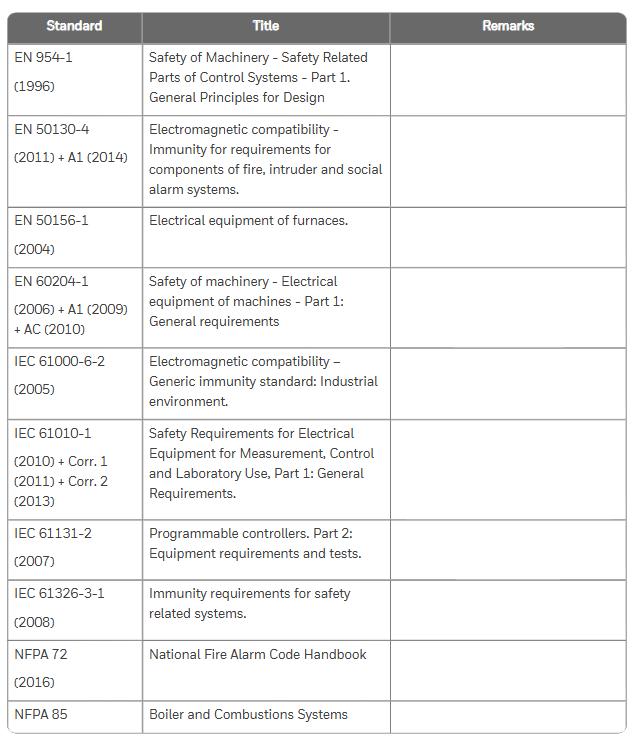
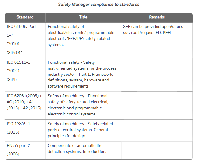
Safety standards: comply with IEC 61508 (functional safety), IEC 61511 (process industry SIS), ISO 13849-1 (mechanical safety), UL 508 (industrial control equipment), etc;
Hazardous Area Certification: ATEX, IECEx (Ex nA IIC T4, applicable to Zone 2 areas), FM 3611 (Class I/II Division 2 hazardous areas, such as chemical explosive environments);
Environmental Protection and Electromagnetic Compatibility: Compliant with RoHS Directive (Halogen Free Design) and EN 61000-6-2 (Electromagnetic Immunity in Industrial Environments), ensuring stable operation in complex industrial environments.
System hardware composition and core modules
The Safety Manager hardware system adopts a three-layer architecture of "cabinet chassis module", with core components including cabinet, controller chassis, IO chassis, power module, control processor module, input/output module, etc. The functions and technical parameters of each component are as follows:
(1) Cabinet: Physical carrier of the system
Standard configuration: Based on Rittal TS 8 series cabinets, default protection level IP20, optional IP54 upgrade; Including cooling fans (such as FANWR-24R, 24V DC with status feedback), thermostats (monitoring cabinet temperature to avoid module overheating), grounding bars (ensuring equipment grounding resistance ≤ 4 Ω), lighting fixtures (easy to maintain);
Key parameters: dimensions (such as 80 × 60 × 200cm, 80 × 80 × 200cm), weight (full load ≤ 550kg), operating temperature (-5~70 ℃, remote cabinet -40~70 ℃).
(2) Chassis: Module Installation and Signal Transmission Core
Divided into controller chassis (CPCHAS series) and IO chassis (IOCHAS series), supporting redundant/non redundant configurations to meet different safety level requirements:
Chassis type, model example, core functions, key specifications
Controller chassis CPCHAS-0001 is equipped with a control processor module to achieve system logic operations. It supports 1-2 Control processors, with a height of 4HE and a standard size of 19 inches
Non redundant IO chassis IOCHAS-0001S is equipped with non redundant IO modules, supporting 18 IO modules connected to on-site sensors/actuators, powered by 5V-R (redundant 5V)
Redundant IO chassis IOCHAS-0001R is equipped with redundant IO modules to improve system fault tolerance. It supports 9 pairs of redundant IO modules and a dual IO bus design
(3) Power Supplies: System Stable Power Supply Guarantee
Provide multiple types of power modules, supporting AC-DC conversion and redundant power supply, to meet different voltage requirements (24V/48V/60V/110V/120V DC). The core models and parameters are as follows:
Power supply model, output specifications, core characteristics, applicable scenarios
PSUNI2424 24V DC/24A, 600W dual overvoltage protection (SIL3 compatible), core controller power supply for operating temperature of -40~70 ℃
PSU-UNI2450U 25-28V DC/43-48A UL 508 certification, 100ms power-off hold, supports parallel expansion and high load IO module cluster power supply
FEEDER-24R 24V DC/63A redundant design, with status feedback relay, overcurrent protection redundant system main power feeder
(4) Control Processor Modules: The System's Brain
QPP-0002 (Quad Processor Pack): Core computing module, dual processors running synchronously, with Flash/RAM storage (battery backup, BKM-0001 module provides battery), supports Watchdog function (monitoring program execution time, memory errors), meets SIL3 requirements;
USI-0002 (Universal Safety Interface): Communication module, providing 2 channels of 10/100M Ethernet and 2 channels of universal serial communication (RS232/485), supporting interconnection with systems such as Expert PKS, with hardware firewall function;
BKM-0001 (Battery and Key Switch Module): A battery and key switch module that includes 2 lithium batteries (backup RAM data, approximately 3 months of battery life), a reset key (clear fault logs), and a forced enable key (allow IO signal forcing).
(5) I/O Modules: Field Signal Interaction
Input module: supports digital/analog signal acquisition, with fault self detection function, core models such as SDI-1624 (24V DC 16 channel digital input), SAI-1620m (16 channel analog input, 0-4V), SDI-1608 (16 channel digital input with ground fault monitoring);
Output module: supports safe digital/analog output, with short-circuit protection, core models such as SDO-0824 (24V DC 8-channel digital output), SAO-0220m (2-channel analog output, 4-20mA);
Converter module: such as BSAI-0420mI (converts 4-20mA to 0-2V, compatible with SAI-0410 module), to achieve matching between on-site signals and module inputs.
Key processes for system installation and maintenance
(1) Hardware Installation Specification
Cabinet installation: Horizontal/vertical installation should meet the requirement of heat dissipation gap (such as reserving 100mm above and below the fan), and grounding should be independent (protective ground and signal ground should be separated);
Module installation: IO modules need to press the "Key Coding" corresponding slot (such as SDI-1624 corresponding to A5/C5 hole positions) to avoid damage caused by incorrect insertion; Redundant modules need to be installed in pairs to ensure synchronous communication;
Cable connection: System interconnection cables (SIC) and communication cables (such as CCI-HSE-01 Ethernet cables) should be wired according to pin definitions to avoid reverse polarity (such as 24V DC power supply "+" connected to pin d8, "0V" connected to pin d10).
(2) Regular maintenance plan
Daily maintenance (daily/weekly): Check the LED indicator light (green normal, red fault), fan operation status, and cable joint tightness; Backup historical data (to USB drive/server);
Regular maintenance (monthly/quarterly): clean the cabinet filter (to avoid dust blockage causing overheating), test the power supply voltage (fluctuation should be ≤± 5%), and measure the cable insulation resistance (≥ 10M Ω);
Annual maintenance: Full module calibration (using original calibration tools such as 9100 calibrator), battery replacement (BKM-0001 module lithium battery replaced every 5 years), firmware upgrade (downloading the latest version from GE Digital official website).
(3) Troubleshooting and Solutions
Based on the "internal system exception" error mentioned in the Nexinstrument document, supplement the general troubleshooting logic of Safety Manager, and organize common troubleshooting solutions in the manual:
Possible causes and solutions for fault phenomena
System error "internal exception": 1. Control processor program crashes; 2. Power supply voltage fluctuations; 3. Module communication interruption: 1. Check the QPP-0002 module's Status LED (red indicates hardware failure and needs to be reset or replaced); 2. Use a multimeter to measure the 24V DC power supply (within the range of 20.4-31.2V); 3. Check the communication light of USI-0002 module (Tx/Rx light does not light up, network cable needs to be unplugged again)
IO module has no signal input 1. Sensor failure; 2. Cable breakage; 3. Module calibration expired. 1. Replace sensor for testing; 2. Use a multimeter to measure the continuity of the cable (such as the signal at pin d12 of SDI-1624 module); 3. Recalibrate the module (refer to SAI-1620m calibration process)
Power module alarm (red light on) 1. Overvoltage/undervoltage; 2. Fan malfunction; 3. Overload 1. Check the input voltage (e.g. PSU-UNI2450U input needs to be between 93-253V AC); 2. Check the fan speed (FANWR-24R speed should be ≥ 1500 RPM); 3. Reduce the number of parallel modules to avoid overloading
Communication interruption (with upper computer): 1. IP address conflict; 2. Protocol mismatch; 3. Network cable failure: 1. Reconfigure the USI-0002 module IP (to avoid conflicts with Expert PKS); 2. Confirm the communication protocol (such as Modbus TCP); 3. Replace the network cable and test the link (using a cable tester)
System configuration and expansion
Model coding rules: The hardware model includes a prefix (FS - non coated, FC - coated, FA - explosion-proof), module type (such as SDI-1624), and suffix (version number, such as V1.1), for example, "FC-SDI-1624" represents a coated 24V DC 16 channel digital input module;
Scalability: Supports adding IO channels through IO expansion modules (such as IO-0002), improving power supply reliability through redundant power supplies (such as RUSPSU-R), and achieving on-site signal terminal switching through FTA modules (such as IOTA-R24).

- OMRON
- ABB
- General Electric
- EMERSON
- Honeywell
- HIMA
- ALSTOM
- Rolls-Royce
- MOTOROLA
- Rockwell
- Siemens
- Woodward
- YOKOGAWA
- FOXBORO
- KOLLMORGEN
- MOOG
- KB
- YAMAHA
- BENDER
- TEKTRONIX
- Westinghouse
- AMAT
- AB
- XYCOM
- Yaskawa
- B&R
- Schneider
- KONGSBERG
- NI
- WATLOW
- ProSoft
- SEW
- ADVANCED
- Reliance
- TRICONEX
- METSO
- MAN
- Advantest
- STUDER
- DANAHER MOTION
- Bently
- Galil
- EATON
- MOLEX
- DEIF
- B&W
- ZYGO
- Aerotech
- DANFOSS
- Beijer
- Moxa
- Rexroth
- Johnson
- WAGO
- TOSHIBA
- BMCM
- SMC
- HITACHI
- HIRSCHMANN
- Application field
- XP POWER
- CTI
- TRICON
- STOBER
- Thinklogical
- Horner Automation
- Meggitt
- Fanuc
- Baldor
- SHINKAWA
- Other Brands
- UniOP
- KUKA
- Iba
- Beckhoff
- ADLINK
-
 National Instruments NI 6587 LVDS Digital I/O Module
-
 National Instruments PCI-6225 Data Acquisition Card
-
 National Instruments NI-9262 Analog Output Module
-
 National Instruments NI 9235 Quarter Bridge Input Module
-
 National Instruments PXIe-8301 Remote Control Module
-
 National Instruments PXI-4071 FlexDMM Module
-
 NI-9234 Sound and Vibration Input 779680-01
-
 NI 9229 Isolated Analog Input Module
-
 NI cDAQ-9178 USB CompactDAQ Chassis
-
 National Instruments NI 9220 143613B-06L Analog Input Module
-
 NI 9229 Analog Input Module
-
 NI 9246 Analog Input Module
-
 NI PXIe-1071 PXI Express Chassis
-
 National Instruments 9225 780159-01 Analog Input Module
-
 NI cDAQ-9171 USB CompactDAQ Chassis
-
 NI PXIe-8840 Embedded PXI Controller
-
 Bonfiglioli A202 UH35 FIA 39.6 Right Angle Reducer
-
 Bonfiglioli BN 90 LA 4 Gearmotor 1.5kW i=14.1
-
 Bonfiglioli BN71A4 Motor with C313PP71 Gearbox
-
 Bonfiglioli MP 130 1 4 STD 114A CD Planetary Gear Head
-
 Bonfiglioli LC155 1 10 STD Gearbox
-
 Bonfiglioli Vectron ACU401-13 FA Inverter
-
 Bonfiglioli AEC500-31A Solar Inverter
-
 Bonfiglioli BN63B6 Geared Motor VF44P
-
 Bonfiglioli Vectron ACT410-23 Inverter
-
 Bonfiglioli FR FRIZ 11/90 Clutch
-
 Bonfiglioli A/11.90 B3 Clutch Brake
-
 Bonfiglioli 50.180.3000 Servo Motor
-
Bonfiglioli NFF 14 112 EE Clutch
-
Bonfiglioli BMD 65 Permanent Magnet Motor
-
 Bonfiglioli MP 080 2 20 STD 73A1 CD Planetary Gearbox
-
 Bonfiglioli VF/VF30/63 P1 1520 Gearbox
-
 Bonfiglioli M3SA4 FD with X F202 H35 10.0 Gearbox
-
 Bonfiglioli ACU401-19A Frequency Inverter 5.5kW
-
 Lafert B6306P-02276 Servo Motor with Bonfiglioli A102
-
Bonfiglioli ACU401-09FA Frequency Inverter 1.1kW
-
 ProMinent Sigma S1CBH12035 with Bonfiglioli BN56B4
-
 Bonfiglioli TR 080 2 20 STD Planetary Gearbox
-
 Bonfiglioli ACT400-040A Frequency Inverter 15kW
-
 Bonfiglioli BE 132 MA 4 Electric Motor 7.5kW
-
 Bonfiglioli W86 U30 P100 Gearbox
-
 Bonfiglioli MP105 2 25 Planetary Gearbox
-
 Bonfiglioli BE160L4 Motor 15 kW
-
BONFIGLIOLI TMP-105 2 25 15 19 40 70 90 Planetary Gearbox
-
Bonfiglioli Vectron ACU401-18 FA Inverter
-
 BONFIGLIOLI BE80B4 Motor with A302 UH35 76.5 P80 VA Gearbox
-
 Bonfiglioli Vectron VCB400-180 Inverter
-
 Bonfiglioli P63B14B3 Motorization Encoder
-
Bonfiglioli Vectron ACT201-13FA Inverter
-
Bonfiglioli F202 H30 P90 Gearbox
-
 Bonfiglioli BN71A4 C313 P P71 Gearmotor
-
 Bonfiglioli ACT201-11FA Frequency Inverter
-
Bonfiglioli ACU410-21 3 FA Inverter 7.5kW
-
Bonfiglioli RA0 60/00 Gear Reducer i=182
-
 Alpha VDS 063-MF1-10-141-BE Planetary Gear 20018280
-
 Stöber FDR 71B/10 Gearmotor 0.37kW
-
 Stöber DW0-2000-037-4 Gearbox 0.25kW
-
 Bonfiglioli M3SA4 FD R with X F252 H35 16.6 Gearbox
-
 Bonfiglioli BN90LA4 Adjustable Gear Motor 1.5kW
-
 Alpha LP 090-MO1-5-111-000 Planetary Gearbox
-
 Bonfiglioli 335 M3 C Planetary Gear Motor
-
 Bonfiglioli TR060 2 18 STD 50C CD 14 S1 OR SB KE Gearbox
-
 Bonfiglioli MP1GD3036L001 Gearbox
-
Bonfiglioli BN90LA4 Gear Motor 1.5 kW
-
 Bonfiglioli A302 UH35 P90 Gearbox
-
Bonfiglioli ACU410-31A5 Inverter
-
 BONFIGLIOLI BMD 118 14 4500 400 165 SS TC1 RES2 P1N S1N CUS JB00013358
-
 Bonfiglioli A302 UH40 P90 Reducer
-
Bonfiglioli ACT201-05FA Inverter
-
 Mannesmann Demag 4APB71-4-G08-PR Gear Motor with Bonfiglioli MVF63/F
-
 BONFIGLIOLI W63 U P80 B5 Gearbox 2G20012741
-
 Bonfiglioli BE80B4 Motor with A202 Gearbox
-
 BONFIGLIOLI VECTRON KEYPAD 179675500 KP500
-
 Bonfiglioli RA0 60/00 Gear Reducer i182
-
 Bonfiglioli C212 F P90 VV Gearbox i=9.6
-
 Bonfiglioli MP105 Servomotor Gear
-
 Mannesmann Demag 4APB71-4-G08-PR Getriebemotor with Bonfiglioli MVF 63/f
-
Bonfiglioli Vectron ACT401-12 FA Inverter
-
 Bonfiglioli BN 80A4 COD.830820106 Motor 0.55 kW IMB5
-
 Bonfiglioli TR060 Gearbox
-
 Silectron Bonfiglioli FT1000-0.75S RFI Filter
-
 Trasmital Bonfiglioli 710C3B50F177G34W1A52VAG Drive
-
Bonfiglioli MAC800-D1 Motorreductor
-
 Bonfiglioli VF 63 V HS Worm Gearbox
-
 Bonfiglioli BN90LA4 Adjustable Gear Motor 1.5kW
-
 Bonfiglioli ACT 400-018 FA Frequency Inverter
-
 Bonfiglioli RAO50DNP90B5-I220 Gear Unit i=200
-
 Bonfiglioli ACT 401-13FA Frequency Inverter SIACT513010001
-
Bonfiglioli ACU210-18 3 FA Active Inverter 4kW
-
 Trasmital Bonfiglioli 709C3B50F177G34W1A52VAG Drive
-
 Bonfiglioli BN27C4 Gear Motor 0.09 kW
-
 Bonfiglioli BN71A4 Electric Motor
-
Bonfiglioli Vectron VCB400-370 Inverter
-
Bonfiglioli Vectron ACU401-18FA Inverter
-
 Bonfiglioli LC120 2 40 STD Gearbox
-
 Bonfiglioli BN63B6 Gear Motor 0.12 kW
-
Bonfiglioli T56BN/4 Asynchronous Motor
-
AEB Atlant D712-4B5 Motor with Bonfiglioli MVF 49F1 Gearbox
-
Bonfiglioli VF110 A P100B14 Worm Gear
-
Trasmital Bonfiglioli Raupengetriebe i 1:122 2174688 2T705C3122002 Travel Drive
-
 Bonfiglioli ACT 401-21A Frequency Inverter
-
 Bonfiglioli VF44 U14 Worm Reducer B03181367918
-
Bonfiglioli VF49 L1 P1 P63B5 Worm Gear i=45
-
Bonfiglioli S2U230S-03F Inverter 0.4kW
-
Ferag 5690512 Uiker TR90L4 Motorreductor with Bonfiglioli C212 F9.6
-
 Bonfiglioli LC120250STD80A1CD14KE Gearbox
-
 Bonfiglioli W63U38 P80 B14 V5 Gearbox
-
 Bonfiglioli VF49A-28-P80-B14 Worm Gearbox
-
 Bonfiglioli BN71B4 W63U64P75 Gearmotor
-
Alpha VDS 063-MF1-10-141-BE Planetary Gearbox
-
Bonfiglioli BN71B4 MVF49 F1 Gearmotor i=36
-
 Bonfiglioli BN 63 B6 Gear Motor 0.12kW
-
 Bonfiglioli SPL400 17F SynPlus Drive 3.7kW
-
Bonfiglioli ACU 401-25A Frequency Inverter
-
Esa 3M2209B5 M71Q Motor with Bonfiglioli MVF49 Gearbox
-
Ferag 5690512 UIKER TR90L4 Gear Motor with Bonfiglioli C212
-
Bonfiglioli A302 UH35 P90 Bevel Gearbox
-
Bonfiglioli GVX1000-1.5-S Inverter Drive 1.5kW
-
Bonfiglioli W63 U 15.0 P80 B14 B Worm Drive
-
Bonfiglioli KP500 Control Panel
-
Bonfiglioli C302PP71 Speed Reducer
-
Bonfiglioli BN71B4 Motor con MVF49 Reductor
-
Bonfiglioli BN71B4 Motor with MVF49 Gearbox i36
-
 Bonfiglioli SYN10S 22001AF Inverter 0.2 kW
-
Motor Power Esa 3M2209B5/M71Q with Tachometer and Bonfiglioli MVF49 Gearbox
-
 Bonfiglioli SYN10 S 220 01 AF Inverter
-
MEZ UD 1104 2.5 kW BONFIGLIOLI Trasmittal 300L19 Gear Motor 300L19.00HZP90AW0A
-
Bonfiglioli Vectron ACT W 401-39 D Inverter


