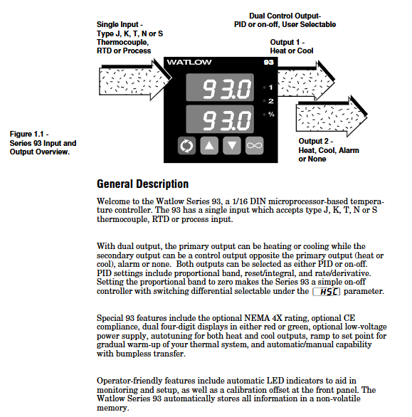
Watlow Series 93 Controller
Power Limit ([PL])
Only heating output is available, with a range of 0-100% (default 100%), limiting the maximum power of heating output to avoid load overload (such as when a small heater is adapted to a high-power controller, power should be limited to prevent burnout).
Calibration offset (CAL)
Range ± 100 ° C/± 180 ° F (or ± 180 units), default 0, used to compensate for measurement deviations caused by sensor installation errors or environmental interference (if the sensor is installed in a heat dissipation area and the actual temperature is 5 ° C higher than the measured value, a+5 ° C offset can be set).
Automatic/manual undisturbed switching
Switching mode: Press the infinite key twice to enter manual mode, the percentage indicator light remains on, and the lower display screen shows the output power (-100% to 100%, negative sign represents cooling); Press the infinite key again to return to automatic mode.
Non disruptive logic: When switching from automatic to manual mode, the output power remains at the PID calculated value before switching; When manually switching to automatic mode, transition to PID control starting from the current manual power to avoid sudden temperature changes.
Sensor fault handling: When the lock level [LOC] is 0/1/2, the sensor will automatically switch to manual mode after an open circuit (maintain the power before the fault, set to 0% if the power is unstable); Directly turn off the output at level 3/4.

Installation and wiring specifications
(1) Installation process
Panel preparation: Cut according to the size of 44.96-45.47mm (width x height). It is recommended to use Greenlee 60287 type 1/16 DIN punch, with a panel thickness of 1.5-9.7mm. When installing multiple units, the distance between adjacent cuts should be ≥ 20mm (to avoid heat dissipation interference).
Sealed installation (IP65 model):
Confirm that the housing gasket (circular with rounded corners) is facing the panel, without distortion or damage, and is embedded in the groove of the housing frame.
Insert the controller into the incision, press the panel side shell, insert the installation ring from the back, ensure that the installation ring buckle is aligned with the shell protrusion, press the buckle with your thumb until you hear a "click" sound, and check that the distance between the panel and the shell is ≤ 0.483mm (ensure sealing).
Dismantling method: Use a thin screwdriver or putty knife to gently pry open the 6 buckles of the installation ring, detach them one by one, and then shake the installation ring back and forth to remove it, avoiding pulling and damaging the shell with force.
(2) Wiring Details
Power wiring
High voltage type (93_ -1 0-00): Terminal 11 is connected to L1 (100-240V AC, actually compatible with 85-264V), terminal 12 is connected to L2, built-in 1A slow melting fuse (250V), cannot be replaced with fast melting fuse.
Low voltage type (93_ -1 1-00 _): Terminal 11 is connected to positive (12-24V AC/DC, actually compatible with 10-26V), terminal 12 is connected to negative, with built-in 2A slow melting fuse. It is strictly prohibited to connect high voltage (which may cause irreversible damage).
Input wiring
Thermocouple: Terminal 3 is connected to the positive pole (if the red color of the J-type thermocouple is negative, pay attention to the polarity), terminal 5 is connected to the negative pole, and the extension wire should be made of the same material as the thermocouple (if the J-type thermocouple uses iron constantan material) to avoid errors; If the external device is not isolated, an isolated thermocouple should be used.
3-wire RTD: Terminal 2 is connected to S1, Terminal 3 is connected to S2, and Terminal 5 is connected to S3. The three leads must have the same specifications (same wire diameter and length), and the total lead resistance should be ≤ 20 Ω to avoid measurement errors caused by resistance differences; 2-wire RTD requires short circuiting terminals 3 and 5, resulting in low accuracy (+2 ° F error per 1 Ω lead resistance).
4-20mA signal: Terminal 2 is connected to the negative pole, terminal 5 is connected to the positive pole, and the input impedance is 5 Ω. It is necessary to ensure that the signal source and controller are grounded together to avoid grounding loops.
Output wiring
Mechanical relay (Output 1: Terminals 8/9/10): Terminal 8 is normally closed (NC), 9 is common terminal (COM), 10 is normally open (NO), maximum load 5A@240V Communication, inductive loads (such as relay coils) require parallel RC suppressors (Watlow 0804-0147-0000), minimum load 100mA@5V DC (to avoid contact oxidation).
4-20mA output (Output 1: Terminal 9/10): Terminal 9 is connected to the positive pole and 10 to the negative pole, with a maximum load impedance of 800 Ω. It is used to control actuators such as frequency converters and valves. Shielded wire is required for wiring, and the shielding layer is grounded at one end (controller end).
Safety Specifications
All wiring must comply with NEC and local electrical standards, with wire diameter of 20-14AWG and terminal torque of 1.4Nm (12in lb), to avoid poor contact caused by looseness and damage to terminals caused by tightness.
- ABB
- General Electric
- EMERSON
- Honeywell
- HIMA
- ALSTOM
- Rolls-Royce
- MOTOROLA
- Rockwell
- Siemens
- Woodward
- YOKOGAWA
- FOXBORO
- KOLLMORGEN
- MOOG
- KB
- YAMAHA
- BENDER
- TEKTRONIX
- Westinghouse
- AMAT
- AB
- XYCOM
- Yaskawa
- B&R
- Schneider
- Kongsberg
- NI
- WATLOW
- ProSoft
- SEW
- ADVANCED
- Reliance
- TRICONEX
- METSO
- MAN
- Advantest
- STUDER
- KONGSBERG
- DANAHER MOTION
- Bently
- Galil
- EATON
- MOLEX
- DEIF
- B&W
- ZYGO
- Aerotech
- DANFOSS
- Beijer
- Moxa
- Rexroth
- Johnson
- WAGO
- TOSHIBA
- BMCM
- SMC
- HITACHI
- HIRSCHMANN
- Application field
- XP POWER
- CTI
- TRICON
- STOBER
- Thinklogical
- Horner Automation
- Meggitt
- Fanuc
- Baldor
- SHINKAWA
- Other Brands


