
Watlow Series 93 Controller
Disassembling the controller after power failure may result in residual voltage at the casing terminals, and insulated gloves should be worn during operation; When installing in high temperature environments, insulation pads should be added between the controller and the heat source to avoid ambient temperatures exceeding 65 ° C (rated operating limit).
Menu Configuration and Operation Guide
(1) Menu Structure
Menu Type Entry Method Core Parameter Function Description
Long press the up and down arrow keys for 3 seconds in the Setup menu, and the lower display will show "['LOC]" [LOC] [Lock Level], [In] (Input Type), [rL]/[rH] (Range), [Ot1]/[Ot2] (Output Mode), [HSC] (Switch Difference), [LAt] (Alarm Lockout). Configure the controller hardware logic, input and output basic parameters, and some parameters (such as [In]) will be reset to factory default values after modification
Press the forward button in the Operation menu to display parameters [Pb1]/[Pb2] (proportional band), [It1]/[rE1] (integral/reset), [dE1]/[rA1] (differential/rate), [ALO]/[AHI] (alarm threshold), [AUT] (self-tuning), [CAL] (calibration offset) in sequence. Real time adjustment of control parameters, start self-tuning, set alarm threshold, and automatically save 5 seconds after parameter modification
Calibration menu: Long press the up and down arrow keys from the settings menu. The lower part displays "[CAL]", and the upper part is set to "[YES]". [000] (0mV input calibration), [500] (50mV input calibration), [440] (44.01 Ω RTD calibration), [rSt] (factory calibration restored). To calibrate the input/output accuracy, professional equipment (such as precision millivolt sources, resistance boxes) is required. The output is turned off during calibration
(2) Key parameter configuration steps
Input type configuration
Open the controller chassis (press the buckles on both sides of the panel to remove it), and set the left DIP switch (8 positions) according to the input type: set the thermocouple to "O N", the RTD to "N O", and the process signal to "O O" (refer to Figure 4.1b for details).
Enter the settings menu and set the [In] parameter (such as setting the J-type thermocouple to "[J]" and the 100 Ω RTD to "[rtd]"), ensuring consistency with the DIP switch, otherwise an error of "[Er7]" will be displayed.
PID parameter self-tuning
Enter the operation menu, set [AUt] to 2 (medium response), press the forward button to start, the controller enters switch control mode (output full power), and starts "learning" when the temperature approaches 90% of the set value.
After self-tuning is completed, [AUt] automatically resets to 0, and the PID parameters ([Pb1]/[It1]/[dE1]) are updated to their optimal values. If manual fine-tuning is required, it can be modified in the operation menu.
Alarm configuration (deviation alarm as an example)
Setting menu: [Ot2] set to "[dEA]" (with display), [SIL] set to "[` On]" (mute enabled), [HSA `] set to "5" (5 ° C lag).
Operation menu: Set [ALO] to "-10" (alarm for temperatures below the set value of 10 ° C), set [AHI] to "+10" (alarm for temperatures above the set value of 10 ° C), lower will flash "[LO]"/"[HI]" when the temperature exceeds the set value, press the infinite key to clear.
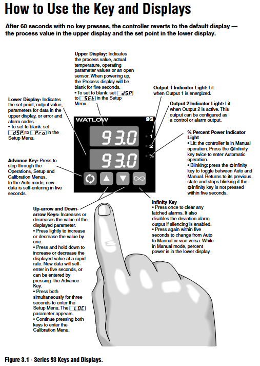
(3) Display and button operation
Display screen function
Upper display screen: default display process value (PV), parameter value is displayed during parameter configuration, "[---]" is displayed when the sensor fails, and an error code (such as "[Er7]") is displayed when the infinite key is pressed twice.
Lower display screen: By default, the set value (SP) is displayed. When configuring parameters, the parameter name (such as "[Pb1]") is displayed. When an alarm is triggered, the alarm type flashes. In manual mode, the output power (such as "50%") is displayed.
Indicator lights: Output 1/2 indicator light (red) on indicates output activation, percentage indicator light (green) constantly on indicates manual mode, flashing indicates mode to be switched.
Shortcut key operation
Return to default display: Press and hold the infinite key for 2 seconds, regardless of the current menu, directly return to PV/SP display.
Clear alarm: After the alarm is triggered, press the infinite key once to clear the locking alarm (the temperature needs to return to the safe range).
Quickly enter the settings menu: Long press the up and down arrow keys on any interface for 3 seconds to directly enter the [LOC] parameter.
Troubleshooting and Maintenance
(1) Common Error Handling
Steps for handling error code reasons
[Er2] RTD input below -200 ° C (or sensor failure) 1. Check if the RTD wiring is loose or broken; 2. Measure the RTD resistance with a multimeter and confirm that it is within the normal range (such as 100 Ω at 0 ° C); 3. If the resistance is normal, enter the calibration menu to perform RTD calibration
[Er4] microprocessor configuration error 1. Power off and restart, observe if it is restored; 2. If it repeatedly occurs, contact Watlow technical support (provide model and fault frequency); 3. Chassis cannot be disassembled by oneself to avoid warranty expiration
- OMRON
- ABB
- General Electric
- EMERSON
- Honeywell
- HIMA
- ALSTOM
- Rolls-Royce
- MOTOROLA
- Rockwell
- Siemens
- Woodward
- YOKOGAWA
- FOXBORO
- KOLLMORGEN
- MOOG
- KB
- YAMAHA
- BENDER
- TEKTRONIX
- Westinghouse
- AMAT
- AB
- XYCOM
- Yaskawa
- B&R
- Schneider
- KONGSBERG
- NI
- WATLOW
- ProSoft
- SEW
- ADVANCED
- Reliance
- TRICONEX
- METSO
- MAN
- Advantest
- STUDER
- DANAHER MOTION
- Bently
- Galil
- EATON
- MOLEX
- DEIF
- B&W
- ZYGO
- Aerotech
- DANFOSS
- Beijer
- Moxa
- Rexroth
- Johnson
- WAGO
- TOSHIBA
- BMCM
- SMC
- HITACHI
- HIRSCHMANN
- Application field
- XP POWER
- CTI
- TRICON
- STOBER
- Thinklogical
- Horner Automation
- Meggitt
- Fanuc
- Baldor
- SHINKAWA
- Other Brands
- UniOP
- KUKA
- Iba
- Beckhoff
-
 Basler D90 96801 100 PCB Card
 -
 Basler XR2002F Voltage Regulator (110 VAC, 48-480 Hz)
 -
 Basler SR8A-2B14B3A Regulator
 -
 Basler 9561500100 Module
 -
 Basler DECS-400 BE1-11 System
 -
 Basler DECS-100-B15 Excitation Control
 -
 Basler SCP 210 Frequency Controller
 -
 Basler SR4A-2B15B3A Static Voltage Regulator
 -
 Basler BE1-32R Power Relay
 -
 Basler PIA2400-17GM Power Interface Adapter
 -
 Basler MVC 232 Manual Voltage Control Module
 -
 Basler SSR 32-12 Static Voltage Regulator
 -
 Basler 5MW AVR Generator Voltage Regulator
 -
 Basler VR63-4B Voltage Regulator
 -
 Basler DECS-100-A05 AVR for Engine Generator
 -
 Basler DECS-100-B15 Automatic Voltage Regulator
 -
 Basler BE1-32R Directional Power Relay
 -
 Basler BE1-87B Differential Relay
 -
 Basler UFOV 260A Protective Module
 -
 Basler 9-2614-02-100 PCB Rev M
 -
Basler DECS-100-B15 Digital AVR
-
 Basler 9284900103 PS DECS-400N
 -
 Basler D4N3H1U Intertie Protection
 -
 Basler DECS-100-B15 A15 AVR
 -
 Basler KR4F Voltage Regulator
 -
 Basler BE26434 T14 Transformer
 -
 Basler SR8A-2B15B3A Regulator
 -
 Westinghouse 774B472A12 AR Relay
 -
Basler DECS-100-B15 AVR
-
Basler XR2002F Regulator 110V
-
Basler SR125-E Static Regulator
-
 Basler SSR 125-12 Regulator
 -
 Basler MOC2599 Motor Pot
 -
 Basler BE1-DFPR Feeder Relay
 -
 Basler CBS 305 Current Boost
 -
 Basler BE1-25 AutoSync
 -
 Basler MVC 300 Voltage Control
 -
 Basler BE3-25A AutoSync
 -
 Basler KR7FF Static Regulator
 -
 Basler 90-49000-100 Regulator
 -
 Basler 880 kVA Dry Type Transformer Specs
 -
 Basler Electric BE1-25 Sync-Check Relay Specs
 -
 Basler SSR 125-12 Voltage Regulator Specs
 -
 Basler Electric BE1-851 Overcurrent Relay Review
 -
Basler Electric 149D930G02 Control Sub-Assembly
-
 Basler Electric BE1-81O/UT Frequency Relay Specs
 -
 Basler Electric BE1-51/27C Overcurrent Relay
 -
 Basler Electric 149D956G02 Industrial Component
 -
Basler Electric BE1-51A Overcurrent Relay Specs
-
 Basler Electric BE1-40Q Loss of Excitation Relay
 -
 Basler DECS-200 Excitation Control System
 -
 Basler DECS-200 Voltage Regulator 56-277V AC / 125V DC
 -
Basler BE1-87T Transformer Differential Relay
-
 Basler RDP-110-S1 Protection Relay
 -
 Basler BE1-700V Digital Protective Relay
 -
 Basler BE1-951 Overcurrent Protection System
 -
 Basler DECS-300 Digital Excitation Control
 -
 Basler DECS-200 Digital Excitation Control
 -
 Basler DECS-200-1C Excitation Control System
 -
Basler DECS-200-1L Digital Excitation Control
-
 Basler Electric BE1-GPS Generator Protection System
 -
Basler Electric DECS-200-1C Digital Excitation Controller
-
 Basler Electric DECS125-15 Excitation Control with Power Module
 -
 Basler Electric BE1-87G Differential Relay
 -
 Basler Electric BE1-11 Protection System I5A3M2P2N0EA00
 -
Basler Electric DECS-200-1C Excitation Control System
-
Basler Electric BE1-11g Generator Protection Relay
-
Basler Electric DECS 125-15-B2C1 V2.0.9 Excitation Control
-
 Basler Electric BE1-81O/UT3ED1JA7N2F Frequency Relay
 -
Basler Electric BE1-81O/UT3EE1YB7N1F Frequency Relay
-
 Basler Electric DECS-200-1L Digital Excitation Control System
 -
Basler DECS125-15-B2C1 Excitation Control
-
 Basler 9507900205 SSR Retrofit Voltage Regulator
 -
 Basler BE2000E Digital Voltage Regulator
 -
 Basler BE1-GPS Generator Protection System
 -
Basler DECS-250-CN1CN1N Digital Excitation Control
-
 Basler DGC-2020 Genset Controller
 -
 Basler BE1-81O UT3ED1LA7N0F Frequency Relay (Variant)
 -
 Basler BE1-81O UT3EE1YA9S0F Frequency Relay (Variant)
 -
Basler BE1-81O Over/Under Frequency Relay
-
Basler DECS125-15 Digital Excitation Control
-
Basler Electric BE1-951 Overcurrent Protection System
-
 Basler Electric BE1-700V Digital Protective Relay
 -
 Basler Electric APR63-5 Automatic Voltage Regulator
 -
Basler Electric BE1-851 Overcurrent Protection System
-
Basler Electric DECS-250-LN1SN1N Excitation Control
-
 Basler Electric BE1-87T Transformer Differential Relay
 -
Basler Electric DECS-200-1L Excitation Control System
-
 Basler Electric 9310300100 DECS-300 Excitation Control
 -
 Basler Electric SSE-N 125-4.5KW Shunt Exciter Regulator
 -
 Basler Electric DGC-2020HD-5NS1DNSBA Genset Controller
 -
Basler Electric BE1-81-O/UT3EE1JB7N1F Frequency Relay
-
Basler Electric BE1-81T1EE1WA0N1F Frequency Relay
-
 Basler Electric BE1-25M1EA6PN5R1F Sync-Check Relay
 -
 Basler Electric BE1-GPS Generator Protection System
 -
Basler Electric DECS-250-LN1SN1N Excitation Control Rev V
-
 Basler Electric DECS-250-CN2CN1N Excitation Control
 -
Basler Electric BE1-50/51B-207 Overcurrent Relay
-
Basler Electric DECS-300-C0N0 Excitation Control System
-
Basler Electric DECS-200 Digital Excitation Control System
-
Basler Electric DECS-250-LN1CN1N Excitation Unit
-
Basler Electric DECS-250 LN2SA1D Excitation Unit Specs
-
Basler Electric BE1-87T Transformer Relay Review
-
Basler Electric BE1-11 Protection System
-
Basler Electric BE1-GPS100-E4N1H1N Protection System
-
 Allen-Bradley 442G-MABH-R Safety Module
 -
 Beckhoff CX1030-0111 PLC Assembly Profile
 -
 FANUC IC693CPU364 PLC Module
 -
 Orange Denmark Type 200816 220 PLC Specs
 -
 OMRON C200H-SNT31 Sysmac PLC Module
 -
 Allen Bradley 20AB022A3AYNANC0 PowerFlex 70
 -
 OMRON C200HW-PCU01 Position Control Unit
 -
 ABB AO845A-eA Analog Output Module
 -
 OMRON CJ1M-CPU22 CPU Unit
 -
 Allen Bradley 100-E265ED11 Contactor
 -
 Honeywell 51304511-100 Interface Module
 -
 SOLEXY BXF3S0101N0018 Gateway Module
 -
 OMRON CJ2H-CPU65 CPU Unit
 -
 Automation Direct GS2-45P0 AC Drive
 -
 M68-2000 2-Axis Motion CNC Controller
 -
 OMRON CJ1M-CPU11 V3.0 PLC CPU Unit
 -
 OMRON CJ1W-NC413 4-Axis Positioning Controller
 -
 OMRON 3G2A3-PRO16 Programming Console HMI
 -
 Siemens 3VT8440-2AA04-2GA2 Molded Case Circuit Breaker
 -
 Siemens 3RT5045 Contactor Series
 -
 OMRON C200HS-CPU01-E SYSMAC PLC Controller
 -
 OMRON C500-NC103-E Positioning Control Unit
 -
 OMRON CJ1W-TC001 Temperature Control Unit


