
WESTINGHOUSE Three Phase Induction Motors
WESTINGHOUSE Three Phase Induction Motors
Product positioning and core values
The large cast iron frame three-phase induction motor (IEC 280/NEMA 444 and above specifications) launched by TECO Westinghouse is the core power equipment for industrial heavy-duty scenarios, designed specifically for large-scale mechanical drive in industries such as steel, chemical, mining, and power. The product has the core advantages of "high rigidity, high reliability, and strong load adaptability". It adopts a cast iron frame structure and supports various installation methods such as horizontal feet and vertical flanges. It is compatible with transmission forms such as couplings, belts, and gears, and can stably drive heavy-duty equipment such as pumps, fans, compressors, and crushers. Its core value lies in ensuring long-term stable operation in complex industrial environments such as -20~+40 ℃, high humidity, and high dust through "strict manufacturing standards, perfect protection systems, and scientific operation and maintenance norms". At the same time, with precise installation and maintenance requirements, it maximizes the service life of equipment and reduces the risk of industrial production interruption.
Overview of Product Core Technical Parameters
(1) Basic specifications and installation parameters
Framework and Structure: Large cast iron frame with IEC 280 (corresponding to NEMA 444) and above, fully enclosed (TEFC) or semi enclosed (TENV) protective structure, excellent dust and moisture resistance.
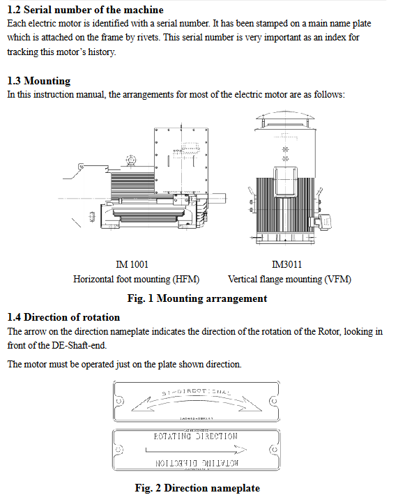
Installation method:
Core types: Horizontal Foot Installation (HFM), Vertical Flange Installation (VFM), supporting customized methods such as vertical hollow shaft and end face installation.
Transmission adaptation: compatible with coupling transmission (rigid/flexible), belt transmission (flat belt/V-belt), chain/gear transmission, to meet different equipment connection needs.
Physical and installation dimensions:
The cast iron frame has strong rigidity and can withstand the weight of the motor and the thrust load during operation. The spacing between the bottom bolt holes is standardized and suitable for industrial universal bases.
Key installation tolerances: Coupling installation end face runout ≤ 0.05mm, shaft diameter tolerance according to H6 standard to ensure transmission accuracy.
(2) Electrical and Environmental Parameters
Parameter category specific specifications
Insulation and resistance: Random winding insulation resistance ≥ 5M Ω, formed winding ≥ 100M Ω (calibrated at 40 ℃, measured with a 500VDC megohmmeter); Insulation level F, allowable temperature rise of 105K
Voltage and frequency: The rated voltage is configured according to the order (commonly 380V, 6kV, 10kV), and the voltage fluctuation is allowed to be ± 10%; Rated frequency 50/60Hz, allowable fluctuation ± 5%
Environmental adaptability working temperature: -20~+40 ℃; Storage temperature: -20~+70 ℃;
Humidity: Fully enclosed models ≤ 95% RH (non condensing), semi enclosed models ≤ 80% RH;
Altitude: ≤ 1000m (for use at altitudes exceeding 1000m, a 10% reduction in capacity is required for every 1000m increase);
Vibration tolerance: ≤ 3.8mm/s during operation, ≤ 2.5mm/s during storage
Protection configuration winding overheating protection: alarm threshold 140 ℃, trip threshold 155 ℃;
Bearing temperature protection: sliding bearing alarm 90 ℃, trip 95 ℃, rolling bearing alarm 95 ℃, trip 105 ℃;
Other protections: overload protection (1.15 times rated current, 1-hour trip), single-phase operation protection, ground fault protection
(3) Run restriction parameters
Start frequency: Up to 2 consecutive starts in cold state (motor temperature ≤ ambient temperature+10 ℃), with an interval of ≥ 5 minutes between each start; Hot state (shutdown after operation) only allows one start, and another start requires cooling for 30-60 minutes (60 minutes at full load and 30 minutes at no load).
Starting current: When starting directly, the starting current is 6-8 times the rated current. It is recommended to configure a soft starter or star delta starter device to reduce grid impact.
Load requirements: During operation, the three-phase current imbalance should not exceed ± 5%. Long term loads should not exceed 110% of the rated power, and short-term overloads (≤ 15 minutes) should not exceed 120%.
Key process specifications for the entire lifecycle
(1) Receiving and Inspection Process
1. Core steps of arrival acceptance
Appearance and packaging inspection: The outer packaging is not damaged or deformed. After opening the box, check that the key parts such as the cast iron frame, end cover, and shaft extension of the motor are not bumped, scratched, or corroded. The fan cover and junction box are intact and undamaged.
Parameter and identification verification: The rated power, voltage, frequency, speed, insulation level, protection level and other parameters on the motor nameplate are consistent with the order; The directional arrow, grounding label, and wiring terminal label are clear and accurate.
Attachment and document verification: The supporting accessories (anchor bolts, couplings, wiring terminals, sealing rings) are complete; The product manual, certificate of conformity, testing report, maintenance manual and other technical documents are complete.
Key function verification: Manually rotate the motor shaft, rotating flexibly without any jamming or abnormal noise; Check that the wiring terminals of auxiliary equipment such as heaters, temperature detectors (PT100/PTC), and vibration sensors are intact and the parameters are compliant.
2. Exception handling
If any transportation damage is found (such as deformation of the frame or bending of the shaft), immediately take photos and record them, synchronize with the carrier and manufacturer, and initiate the claim process.
If the parameters do not match the order or the attachments are missing, please contact the manufacturer in a timely manner to coordinate replacement or supplementation. Unauthorized modification and use are prohibited.
(2) Storage Management Standards
1. Storage environment requirements
The storage site should be clean, dry, and well ventilated, with a temperature controlled between 10-50 ℃ and a relative humidity of ≤ 60%. It should be kept away from heat sources, cold sources, or corrosion sources such as boilers, cold storage, and chemical warehouses.
The motor should be placed on a wooden tray or metal bracket, at least 10cm above the ground, to avoid direct contact with the ground and moisture; Reserve a passage of ≥ 50cm around for ventilation and inspection.
Do not stack heavy or sharp objects in the storage area to avoid colliding with the motor; Avoid storing in strong vibration environments (such as near air compressors) to prevent bearing corrosion or loose windings.
2. Moisture prevention and protective measures
Moisture proof treatment: Activate the built-in space heater of the motor (powered according to the voltage indicated on the nameplate), or place a 25-40W built-in incandescent lamp in the junction box to maintain the internal temperature of the motor 3 ℃ higher than the dew point of the environment, to prevent winding condensation and moisture.
Bearing protection: Manually rotate the motor shaft 3-5 times a month to evenly distribute the lubricating grease and prevent corrosion of the bearing raceway; Long term storage (≥ 3 months) requires the addition of specialized lubricating grease (ExxonMobil Polyrex EM).
Electrical protection: The junction box is sealed properly, and the terminals are coated with rust proof grease; If the motor is equipped with a water cooling system, it is necessary to drain the accumulated water in the pipeline to prevent frost cracking or internal corrosion in winter.
3. Regular inspection and maintenance
Perform insulation resistance testing (using a 500VDC megohmmeter) every 3 months and record the test data. If the insulation resistance is lower than the standard value (random winding<5M Ω/formed winding<100M Ω), drying treatment (using hot air drying or low-voltage electrification drying) is required.
Verify the accuracy of temperature detectors and vibration sensors every 6 months, check the working status of heaters, and ensure the normal operation of auxiliary equipment.
Additional measures for long-term storage (≥ 6 months): Remove external connecting components such as couplings, lift the electric brush (if it is a wound rotor motor), apply anti rust oil to the shaft extension end and wrap it with a protective cover; Regularly inspect the surface coating of the motor, and promptly touch up the paint if rust appears.
(3) Installation and commissioning specifications
1. Preparation before installation
Foundation and base requirements: The installation foundation should be made of reinforced concrete structure, with strength meeting the load requirements during motor operation (bearing capacity ≥ 3 times the weight of the motor), and the levelness error of the foundation plane should be ≤ 0.04mm/m.
Using a rigid bottom plate or common base, cushioning pads (such as rubber cushioning pads or spring shock absorbers) are placed between the bottom plate and the foundation to reduce vibration transmission; The anchor bolts should use high-strength bolts (grade ≥ 8.8) and reserve secondary grouting holes.
Preparation of tools and materials: Prepare installation tools and consumables such as dial gauges, level gauges, torque wrenches, grouting materials (epoxy resin or fine aggregate concrete), terminal blocks, insulation tape, etc.
2. Core installation steps
Motor fixation: Place the motor on the base plate, adjust the levelness (measured with a spirit level, with longitudinal and transverse levelness errors ≤ 0.04mm/m), insert the anchor bolts and pre tighten them, then perform secondary grouting. After the grouting material strength reaches the design requirements (usually ≥ 7 days), tighten the anchor bolts according to the specified torque (recommended torque values refer to the motor manual).
Transmission connection installation:
Coupling transmission: Choose a rigid or flexible coupling that matches the motor shaft diameter, and use a dial gauge to check the coaxiality and parallelism during installation. When the speed is less than 2500rpm, the coaxiality error is ≤ 0.04mm (rigid coupling)/≤ 0.05mm (flexible coupling), and the parallelism error is ≤ 0.03mm. Reserve 1-2.4mm gap at the coupling end to avoid collision during operation.
Belt drive: The diameter of the pulley should meet the minimum recommended diameter of the motor (such as the minimum diameter of the V-pulley for a 45kW 4P motor ≥ 265mm), and the end face runout of the pulley after installation should be ≤ 0.1mm. The center distance of the pulley should be adjusted according to the length of the belt, and the tension of the belt should be moderate (press the midpoint of the belt, and the sinking amount should be 1%~2% of the length of the leather belt) to avoid slipping or excessive stress.
Electrical wiring:
Recheck the insulation resistance of the winding before wiring to ensure it meets the standard; Connect the wires according to the wiring diagram inside the motor junction box. The cross-section of the power cable should match the rated current (copper core cable ≥ 1.5mm ²/kW), and the wiring terminals should be tightly pressed to avoid virtual connection and heat generation.
The motor casing must be reliably grounded with a grounding resistance of ≤ 4 Ω; If the motor is a high-voltage model (6kV/10kV), it should be wired according to the high-voltage electrical regulations and equipped with insulation covers and warning signs.
Check the phase sequence to ensure that the motor direction is consistent with the equipment requirements (confirmed through jog testing, if the direction is opposite, swap any two-phase power supply wiring).
3. Debugging and trial operation
Pre startup inspection:
Mechanical inspection: Rotate the motor shaft again to confirm that there is no jamming; Check the tightness of the coupling bolts and pulleys, and ensure that the fan cover is securely installed; The oil level of the sliding bearing is at the center of the oil gauge, and the oil ring rotates smoothly.
Electrical inspection: The power supply voltage is stable (fluctuation ≤ ± 5%), and the protector parameters are set correctly (overload protection current 1.15 times rated current, trip time 1 hour); The wiring of auxiliary equipment such as heaters and temperature detectors is correct and working properly.
Auxiliary system inspection: The water inlet temperature of the water-cooled motor is controlled at 5-30 ℃, the water pressure is 0.2-0.4MPa, and there is no leakage; Start the cooling fan of the forced ventilation motor 15 minutes in advance to ensure normal heat dissipation.
Trial operation:
No load test run: Start the motor and run it without load for 30-60 minutes. Monitor the three-phase current (unbalance degree ≤± 5%), bearing temperature (≤ 70 ℃), vibration value (≤ 2.8mm/s), and ensure no abnormal noise, oil leakage, or burning smell.
Load test run: Gradually increase the load (by 20% of the rated load each time, stabilize for 30 minutes, and then increase again) until reaching the rated load, and continue running for 2-4 hours; Monitor winding temperature (≤ 105 ℃), bearing temperature (sliding bearings ≤ 90 ℃, rolling bearings ≤ 95 ℃), vibration value (≤ 3.8mm/s), and all parameters must be within the allowable range.
Debugging records: Detailed records of voltage, current, temperature, vibration and other data during the trial operation process, forming a debugging report as a reference for subsequent maintenance.
(4) Operation and Operating Standards
1. Key points for daily operation
Before starting the motor, it is necessary to confirm that the equipment load has been disconnected or is in a light load state to avoid heavy load starting; Observe the starting current during startup. If the startup time is too long (more than 10 seconds) or the starting current is abnormally high, immediately stop the machine for troubleshooting.
During operation, real-time monitoring of parameters such as three-phase current, voltage, winding temperature, bearing temperature, vibration value, etc. is carried out through the control cabinet display screen or on-site instruments. If any abnormalities are found (such as sudden increase in current, temperature exceeding the standard, and intensified vibration), the load should be immediately reduced or the machine should be stopped for inspection.
It is prohibited to disassemble fan covers, junction boxes, and other components while the motor is running. It is also forbidden to wipe the running motor with a damp cloth to avoid electric shock or burns.
After the motor stops, wait for the speed to completely drop to zero before performing load switching or maintenance operations; Frequent start stop is prohibited (in accordance with the frequency limit) to avoid overheating of the winding.
2. Handling of special working conditions
When the voltage fluctuation of the power grid exceeds ± 10%, it is necessary to reduce the load in a timely manner to avoid motor overheating; If the voltage continues to be abnormal, stop the machine and wait for the power grid to return to normal.
When the ambient temperature exceeds 40 ℃, the load should be reduced (by 10% for every 5 ℃ increase), and ventilation and heat dissipation should be strengthened; When the ambient temperature is below -20 ℃, the motor needs to be preheated (heated by a heater for 30-60 minutes) before starting to avoid lubricating oil solidification.
When there is slight abnormal noise or vibration in the motor, immediately investigate the cause (such as loose coupling, uneven belt tension, lack of bearing grease), prohibit operation with faults, and prevent the fault from expanding.
Core maintenance and upkeep system
(1) Maintenance cycle and core projects
Maintenance cycle, maintenance level, core project operation points
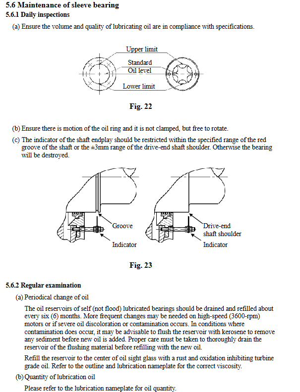
Daily inspection of oil level, leakage monitoring, and visual inspection. The sliding bearing oil level is at the center of the oil gauge and there is no dripping; There is no dust accumulation on the surface of the motor, and the fan is running normally
Weekly routine inspection of bolt tightening, coupling status, current monitoring anchor bolts, coupling bolts, and junction box bolts for no looseness; Three phase current balance, no abnormal fluctuations
Monthly focus on checking filter cleanliness, belt tension adjustment, vibration detection, cleaning of bearing lubricating oil filters, and cooling fan filters; Adjust the belt tension and replace the aging belt; Vibration value ≤ 3.8mm/s
Quarterly intermediate maintenance insulation resistance testing, bearing grease repair, winding cleaning insulation resistance ≥ 5M Ω; grease repair according to bearing model (such as 6310 bearing with 40g, 22218 bearing with 120g); Compressed air (≤ 4kg/cm ²) to clean the dust on the surface of the winding
Every six months, advanced maintenance oil replacement, end cover sealing inspection, heater calibration, sliding bearing replacement, rust and oxidation suppression turbine oil (ISO VG32/VG68); Check the sealing ring of the end cap and replace it if it ages; Verify the working status of the heater
Annual in-depth maintenance of vibration analysis, re alignment of couplings, and evaluation of winding insulation professional instruments for vibration spectrum analysis to identify potential faults; Re check the coaxiality of the coupling, and adjust if the deviation exceeds the standard; Evaluate the insulation status of the winding and perform drying treatment if necessary
Open the cover every 2 years to check the status of the coil, detect bearing wear, and measure rotor clearance. Open the end cover and inspect the stator coil for discoloration, aging, and looseness; Detect bearing wear (radial clearance ≤ 0.1mm); Measure air gap (uniformity error ≤ 10%)
Disassemble and maintain the rotor guide bar inspection, stator core inspection, and bearing replacement every 4 years. Disassemble the motor and check that there is no looseness or cracking at the welding point between the rotor guide bar and the end ring; Check whether the stator core is corroded or deformed; Replace the rolling bearings and re grind the sliding bearings
(2) Core component maintenance details
1. Winding maintenance
Cleaning: Use compressed air (pressure ≤ 4kg/cm ²) to blow the dust on the surface of the winding from the inside out. If there is oil stains, wipe them with alcohol or neutral cleaner. Do not use chlorine containing solvents (such as acetone) to avoid corroding the insulation layer.
Insulation testing: Use a 500VDC megohmmeter to measure the insulation resistance of the winding every quarter. Before measurement, disconnect auxiliary equipment such as heaters and temperature detectors, and discharge after measurement; If the insulation resistance is lower than the standard value, use hot air drying (temperature 60-80 ℃, continuous for 24-48 hours) or low-voltage electrification drying (apply 10%~20% of the rated voltage, continuous for 12-24 hours).
Moisture protection: When the motor is idle for more than one month, activate the space heater to maintain the winding temperature 3 ℃ above the dew point; Before restarting after a long-term shutdown, insulation resistance testing must be conducted to meet the standard before starting.
2. Bearing maintenance
Lubricant selection: ExxonMobil Polyrex EM grease is used by default for rolling bearings, and mixing different brands and types of grease is prohibited; Sliding bearings use rust proof oxidation inhibiting turbine oil, 2-pole motors use ISO VG32, and 6-pole and above motors use ISO VG68.
Guidelines for fat supplementation and replacement:
Rolling bearing grease cycle: 63XX series 1500-3000 hours, 222XX series 300-1000 hours; Under belt drive, high temperature environment (≥ 40 ℃) or dust environment, the grease replenishment cycle is halved.
Lubricating amount: Calculated based on the inner diameter of the bearing, 5-10g of grease should be added every 10mm inner diameter (such as 40g for 6310 bearing and 120g for 6318 bearing) to avoid excessive grease filling and bearing heating.
Greasing operation: Clean the oil drain hole on the bearing end cover before greasing, grease it during operation, run it without load for 10-30 minutes after greasing, drain the old grease, and then tighten the oil drain hole bolt.
Wear detection: Monitor the vibration value of the bearing through a vibration sensor. If the vibration value exceeds 3.8mm/s or the bearing temperature continues to rise (rolling bearings>95 ℃, sliding bearings>90 ℃), the machine should be stopped to check the wear condition of the bearing, and the bearing should be replaced if necessary.
3. Maintenance of transmission system
Coupling maintenance: Check the tightening of coupling bolts every month, and tighten them promptly if they are loose; Check the rubber pads (flexible couplings) or elastomers of the coupling every six months, and replace them immediately if aging or cracking occurs; Re check the coaxiality of the coupling every year, and adjust if the deviation exceeds the standard.
Belt drive maintenance: Check the belt tension every week. If there is slippage or abnormal noise, adjust the center distance or replace the belt in a timely manner; Check the wear of the pulley every 3 months. If the wear depth of the groove exceeds 2mm, replace the pulley; It is prohibited to mix belts of different specifications and brands.
(3) Common troubleshooting and solutions
Common causes and troubleshooting steps for fault phenomena
Unable to start (no movement) due to power failure, broken wiring, blown fuses, tripped protectors, and rotor jamming. 1. Check the power switch and fuses, and replace them with matching fuses if they are blown; 2. Check the wiring terminals and repair broken or disconnected wires; 3. Reset the protector and investigate the cause of the trip (such as overload, short circuit); 4. Manually rotate the motor shaft. If it is stuck, check whether the coupling is stuck or the bearing is damaged. If necessary, disassemble and repair it
Immediately trip the winding for short circuit/grounding, single-phase operation, overload, and incorrect protector parameter settings after startup. 1. Use a megohmmeter to check the insulation resistance of the winding. If there is a short circuit or grounding, disassemble the motor and repair the winding; 2. Check if the three-phase power supply is missing phase and repair the broken wire; 3. Reduce the load and ensure that the load does not exceed the rated power; 4. Adjust the parameters of the protector (overload current 1.15 times rated current)
Overheating during operation (winding temperature>105 ℃), overload, ventilation blockage, environmental temperature exceeding the standard, three-phase current imbalance, winding insulation aging 1. Reduce the load to ensure that the load is within the rated range; 2. Clean the dust from the cooling fan and heat sink to ensure smooth ventilation; 3. Improve environmental heat dissipation (such as adding ventilation equipment); 4. Check the voltage of the three-phase power supply and repair the fault that caused the current imbalance; 5. Check the insulation of the winding, and replace the winding if it has aged
Insufficient lubrication due to high temperature/abnormal noise of bearings, deterioration of lubricating grease, improper installation, bearing wear, and entry of foreign objects. 1. Supplement or replace qualified lubricating grease; 2. Recheck the coaxiality of the coupling and adjust it to the allowable range; 3. Disassemble the bearing and check for wear. If the raceway or ball bearings are worn or corroded, replace the bearing; 4. Clean the bearing end cover, remove foreign objects, and replace the sealing ring
Vibration exceeding the standard (>3.8mm/s), rotor imbalance, insufficient foundation stiffness, coupling eccentricity, and uneven belt tension. 1. Perform dynamic balance correction on the rotor; 2. Strengthen the installation foundation and add shock-absorbing pads; 3. Adjust the coaxiality of the coupling and tighten the foundation bolts; 4. Adjust the belt tension and replace worn pulleys
Recycling and compliant disposal
(1) Scrap judgment criteria
The cast iron frame of the motor is severely deformed and cracked, and cannot be repaired;
The stator winding is burnt and aged, and the repair cost exceeds 50% of the price of a new motor;
The rotor guide bar is loose or broken, and the unevenness of the air gap exceeds 10%;
The bearing is severely worn, the shaft is bent and deformed, and cannot be corrected;
The motor has been in operation for over 15 years, with frequent malfunctions and high maintenance costs.
(2) Recycling and disposal process
1. Material classification and recycling
Cast iron components such as cast iron frames, end caps, and bottom plates, as well as steel components such as steel fan covers and anchor bolts, are classified and disassembled before being handed over to professional recycling institutions for recycling and reuse;
The copper wires in the stator winding should be disassembled and recycled separately to avoid mixing with other metals;
Insulation materials (such as winding insulation paper, coil binding tape), rubber sealing rings, belts and other non-metallic materials are classified as recyclable and non recyclable, and non recyclable parts are disposed of as general industrial solid waste.
2. Hazardous waste disposal
Waste lubricating grease in motor bearings and waste lubricating oil in sliding bearings are classified as hazardous waste and need to be collected in specialized sealed containers. They should be handed over to qualified hazardous waste treatment institutions for compliant disposal, and it is prohibited to discharge or dump them indiscriminately;
If the motor is a permanent magnet motor, it needs to be heated to 300 ℃ for demagnetization treatment before recycling to avoid strong magnetic fields interfering with electronic devices or causing harm to the human body.
3. Compliance requirements
The recycling and disposal process must comply with local environmental regulations, retain recycling vouchers and disposal contracts, and ensure traceability throughout the entire process;
It is prohibited to dismantle or burn the motor without authorization to avoid environmental pollution or safety accidents.
- OMRON
- ABB
- General Electric
- EMERSON
- Honeywell
- HIMA
- ALSTOM
- Rolls-Royce
- MOTOROLA
- Rockwell
- Siemens
- Woodward
- YOKOGAWA
- FOXBORO
- KOLLMORGEN
- MOOG
- KB
- YAMAHA
- BENDER
- TEKTRONIX
- Westinghouse
- AMAT
- AB
- XYCOM
- Yaskawa
- B&R
- Schneider
- KONGSBERG
- NI
- WATLOW
- ProSoft
- SEW
- ADVANCED
- Reliance
- TRICONEX
- METSO
- MAN
- Advantest
- STUDER
- DANAHER MOTION
- Bently
- Galil
- EATON
- MOLEX
- DEIF
- B&W
- ZYGO
- Aerotech
- DANFOSS
- Beijer
- Moxa
- Rexroth
- Johnson
- WAGO
- TOSHIBA
- BMCM
- SMC
- HITACHI
- HIRSCHMANN
- Application field
- XP POWER
- CTI
- TRICON
- STOBER
- Thinklogical
- Horner Automation
- Meggitt
- Fanuc
- Baldor
- SHINKAWA
- Other Brands
- UniOP
- KUKA
- Iba
- Beckhoff
-
 Basler D90 96801 100 PCB Card
 -
 Basler XR2002F Voltage Regulator (110 VAC, 48-480 Hz)
 -
 Basler SR8A-2B14B3A Regulator
 -
 Basler 9561500100 Module
 -
 Basler DECS-400 BE1-11 System
 -
 Basler DECS-100-B15 Excitation Control
 -
 Basler SCP 210 Frequency Controller
 -
 Basler SR4A-2B15B3A Static Voltage Regulator
 -
 Basler BE1-32R Power Relay
 -
 Basler PIA2400-17GM Power Interface Adapter
 -
 Basler MVC 232 Manual Voltage Control Module
 -
 Basler SSR 32-12 Static Voltage Regulator
 -
 Basler 5MW AVR Generator Voltage Regulator
 -
 Basler VR63-4B Voltage Regulator
 -
 Basler DECS-100-A05 AVR for Engine Generator
 -
 Basler DECS-100-B15 Automatic Voltage Regulator
 -
 Basler BE1-32R Directional Power Relay
 -
 Basler BE1-87B Differential Relay
 -
 Basler UFOV 260A Protective Module
 -
 Basler 9-2614-02-100 PCB Rev M
 -
Basler DECS-100-B15 Digital AVR
-
 Basler 9284900103 PS DECS-400N
 -
 Basler D4N3H1U Intertie Protection
 -
 Basler DECS-100-B15 A15 AVR
 -
 Basler KR4F Voltage Regulator
 -
 Basler BE26434 T14 Transformer
 -
 Basler SR8A-2B15B3A Regulator
 -
 Westinghouse 774B472A12 AR Relay
 -
Basler DECS-100-B15 AVR
-
Basler XR2002F Regulator 110V
-
Basler SR125-E Static Regulator
-
 Basler SSR 125-12 Regulator
 -
 Basler MOC2599 Motor Pot
 -
 Basler BE1-DFPR Feeder Relay
 -
 Basler CBS 305 Current Boost
 -
 Basler BE1-25 AutoSync
 -
 Basler MVC 300 Voltage Control
 -
 Basler BE3-25A AutoSync
 -
 Basler KR7FF Static Regulator
 -
 Basler 90-49000-100 Regulator
 -
 Basler 880 kVA Dry Type Transformer Specs
 -
 Basler Electric BE1-25 Sync-Check Relay Specs
 -
 Basler SSR 125-12 Voltage Regulator Specs
 -
 Basler Electric BE1-851 Overcurrent Relay Review
 -
Basler Electric 149D930G02 Control Sub-Assembly
-
 Basler Electric BE1-81O/UT Frequency Relay Specs
 -
 Basler Electric BE1-51/27C Overcurrent Relay
 -
 Basler Electric 149D956G02 Industrial Component
 -
Basler Electric BE1-51A Overcurrent Relay Specs
-
 Basler Electric BE1-40Q Loss of Excitation Relay
 -
 Basler DECS-200 Excitation Control System
 -
 Basler DECS-200 Voltage Regulator 56-277V AC / 125V DC
 -
Basler BE1-87T Transformer Differential Relay
-
 Basler RDP-110-S1 Protection Relay
 -
 Basler BE1-700V Digital Protective Relay
 -
 Basler BE1-951 Overcurrent Protection System
 -
 Basler DECS-300 Digital Excitation Control
 -
 Basler DECS-200 Digital Excitation Control
 -
 Basler DECS-200-1C Excitation Control System
 -
Basler DECS-200-1L Digital Excitation Control
-
 Basler Electric BE1-GPS Generator Protection System
 -
Basler Electric DECS-200-1C Digital Excitation Controller
-
 Basler Electric DECS125-15 Excitation Control with Power Module
 -
 Basler Electric BE1-87G Differential Relay
 -
 Basler Electric BE1-11 Protection System I5A3M2P2N0EA00
 -
Basler Electric DECS-200-1C Excitation Control System
-
Basler Electric BE1-11g Generator Protection Relay
-
Basler Electric DECS 125-15-B2C1 V2.0.9 Excitation Control
-
 Basler Electric BE1-81O/UT3ED1JA7N2F Frequency Relay
 -
Basler Electric BE1-81O/UT3EE1YB7N1F Frequency Relay
-
 Basler Electric DECS-200-1L Digital Excitation Control System
 -
Basler DECS125-15-B2C1 Excitation Control
-
 Basler 9507900205 SSR Retrofit Voltage Regulator
 -
 Basler BE2000E Digital Voltage Regulator
 -
 Basler BE1-GPS Generator Protection System
 -
Basler DECS-250-CN1CN1N Digital Excitation Control
-
 Basler DGC-2020 Genset Controller
 -
 Basler BE1-81O UT3ED1LA7N0F Frequency Relay (Variant)
 -
 Basler BE1-81O UT3EE1YA9S0F Frequency Relay (Variant)
 -
Basler BE1-81O Over/Under Frequency Relay
-
Basler DECS125-15 Digital Excitation Control
-
Basler Electric BE1-951 Overcurrent Protection System
-
 Basler Electric BE1-700V Digital Protective Relay
 -
 Basler Electric APR63-5 Automatic Voltage Regulator
 -
Basler Electric BE1-851 Overcurrent Protection System
-
Basler Electric DECS-250-LN1SN1N Excitation Control
-
 Basler Electric BE1-87T Transformer Differential Relay
 -
Basler Electric DECS-200-1L Excitation Control System
-
 Basler Electric 9310300100 DECS-300 Excitation Control
 -
 Basler Electric SSE-N 125-4.5KW Shunt Exciter Regulator
 -
 Basler Electric DGC-2020HD-5NS1DNSBA Genset Controller
 -
Basler Electric BE1-81-O/UT3EE1JB7N1F Frequency Relay
-
Basler Electric BE1-81T1EE1WA0N1F Frequency Relay
-
 Basler Electric BE1-25M1EA6PN5R1F Sync-Check Relay
 -
 Basler Electric BE1-GPS Generator Protection System
 -
Basler Electric DECS-250-LN1SN1N Excitation Control Rev V
-
 Basler Electric DECS-250-CN2CN1N Excitation Control
 -
Basler Electric BE1-50/51B-207 Overcurrent Relay
-
Basler Electric DECS-300-C0N0 Excitation Control System
-
Basler Electric DECS-200 Digital Excitation Control System
-
Basler Electric DECS-250-LN1CN1N Excitation Unit
-
Basler Electric DECS-250 LN2SA1D Excitation Unit Specs
-
Basler Electric BE1-87T Transformer Relay Review
-
Basler Electric BE1-11 Protection System
-
Basler Electric BE1-GPS100-E4N1H1N Protection System
-
 Allen-Bradley 442G-MABH-R Safety Module
 -
 Beckhoff CX1030-0111 PLC Assembly Profile
 -
 FANUC IC693CPU364 PLC Module
 -
 Orange Denmark Type 200816 220 PLC Specs
 -
 OMRON C200H-SNT31 Sysmac PLC Module
 -
 Allen Bradley 20AB022A3AYNANC0 PowerFlex 70
 -
 OMRON C200HW-PCU01 Position Control Unit
 -
 ABB AO845A-eA Analog Output Module
 -
 OMRON CJ1M-CPU22 CPU Unit
 -
 Allen Bradley 100-E265ED11 Contactor
 -
 Honeywell 51304511-100 Interface Module
 -
 SOLEXY BXF3S0101N0018 Gateway Module
 -
 OMRON CJ2H-CPU65 CPU Unit
 -
 Automation Direct GS2-45P0 AC Drive
 -
 M68-2000 2-Axis Motion CNC Controller
 -
 OMRON CJ1M-CPU11 V3.0 PLC CPU Unit
 -
 OMRON CJ1W-NC413 4-Axis Positioning Controller
 -
 OMRON 3G2A3-PRO16 Programming Console HMI
 -
 Siemens 3VT8440-2AA04-2GA2 Molded Case Circuit Breaker
 -
 Siemens 3RT5045 Contactor Series
 -
 OMRON C200HS-CPU01-E SYSMAC PLC Controller
 -
 OMRON C500-NC103-E Positioning Control Unit
 -
 OMRON CJ1W-TC001 Temperature Control Unit


