
Triconex Tricon™ v9–v11 Systems Planning and Installation Guide
Triconex Tricon™ v9–v11 Systems Planning and Installation Guide
System core positioning and core characteristics
Product positioning: Designed specifically for industrial safety critical scenarios, it can undertake core tasks such as emergency shutdown (ESD), fire and gas detection (F&G), burner management (BMS), process control, etc. It is widely used in fields such as petrochemicals, nuclear power generation, semiconductor manufacturing, and offshore platforms that require high reliability and safety.
Deep analysis of core architecture:
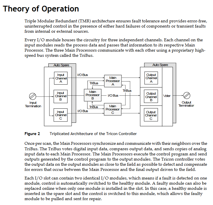
Triple Modular Redundancy (TMR): Three completely independent system channels (A/B/C) execute control programs in parallel, each channel containing independent processors, I/O circuits, and power paths. The input data is verified through a hardware voting mechanism (2/3 voting for digital values and median for analog values), and the output data is voted on at the nearest output module end to ensure that the fault channel does not affect the system output.
Dual redundancy design: the power module and some communication modules (such as TCM/UCM) adopt dual redundancy configuration. When any module fails, the standby module takes over seamlessly without downtime.
Channel isolation: Three channels are completely physically and electrically isolated, and a single channel fault will not spread to other channels. The faulty channel can be replaced online, and the system will automatically resume full TMR operation after replacement.
Key advantage details:
Online maintenance capability: All modules (processor, I/O, power supply, communication) support hot swapping, and there is no need to interrupt the control process when replacing them. The module automatically completes parameter synchronization after insertion (hot backup module).
Fault self diagnosis: Each module is equipped with an independent diagnostic circuit, covering power supply faults, communication faults, I/O circuit faults, module hardware faults, etc. The diagnostic coverage rate is over 99%, and fault information is reported in real-time through indicator lights, alarm contacts, or software.
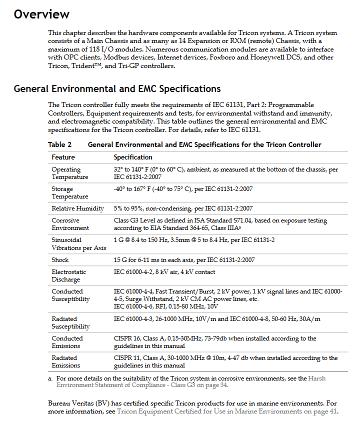
Anti interference capability: Compliant with IEC 61000 series EMC standards, with electrostatic discharge (ESD) protection up to 8kV (air)/4kV (contact) and surge protection up to 2kV, suitable for industrial strong interference environments.
Remote scalability flexibility: With SRXM single-mode fiber modules, remote I/O racks can be deployed 7.5 miles (12 kilometers) away from the main rack, supporting multi site cascading and meeting the distributed control needs of large factories.
International Certification and Compliance:
Functional safety certification: T Ü V Rheinland certification, compliant with IEC 61508 (SIL 1-3), IEC 61511 (Process Industry Functional Safety), EN 54 (Fire and Gas Detection), NFPA 85/86 (Burner Management).
Environmental and safety certifications: CSA certification (compliant with CAN/CSA-C22.2, UL 61010), FM certification (Class I, Division 2 hazardous areas), NRC certification (nuclear 1E applications), ATEX certification (Zone 2 hazardous areas), CE certification (compliant with EMC Directive 2004/108/EC and Low Voltage Directive 2006/95/EC).
Detailed Description of Hardware Components (Supplementary Parameters and Adaptation Relationships)
(1) Chassis: System Installation and Expansion Core
Type, Model, Core Parameters, Adaptation Module, and System Version Application Scenarios
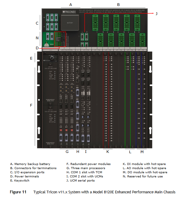
Main frame 8110 size: 48.3cm (width) x 57.8cm (height) x 45.1cm (depth); Support 6 sets of logical I/O slots (2 physical slots per set); TriBus speeds of 25Mbps (paired with 3008/3009 MP) and 4Mbps (paired with 3006/3007 MP); Includes 2 power module slots, 3 processor slots, and 1 communication slot (COM 1) to support all I/O modules and communication modules (TCM/EICM/NCM); Compatible with v9.0-11. x system standard system core, suitable for medium to large control scenarios
The size of the enhanced mainframe 8120E is the same as that of 8110; Support 5 sets of logical I/O slots; TriBus speed of 1000Mbps (only compatible with 3009 MP); COM 1 (TCM specific) and COM 2 (UCM specific, 2 physical slots) only support 3009 MP and UCM modules; Adapting to v11. x system requires high-speed communication and integration with Foxboro Evo system scenarios
Expansion rack 8111 has the same size as 8110; Supports 8 sets of logical I/O slots; No processor slot; Connected to the host rack through the I/O bus, supporting all I/O modules up to a maximum distance of 30 meters; Adapt to v9.0-11. x system local I/O expansion, used when the host rack I/O slots are insufficient
Low density expansion rack 8121 supports 5 sets of logical I/O slots; Compatible with HART interface module (2770H/2870H); I/O bus speed of 375Kbps supports low-density I/O modules and HART modules; Adapt to scenarios where the v10.4-11. x system requires HART protocol communication and fewer I/O points
Remote rack 8112 supports 6 sets of logical I/O slots; Need to be paired with RXM/SRXM remote expansion module; Connected to the mainframe through fiber optic cables, supporting all I/O modules up to a maximum distance of 12 kilometers; Adapt to remote area I/O deployment of v9.0-11. x systems (such as factory remote devices)
(2) Power module: Stable power supply guarantee
Model Input Voltage Range Output Parameters Key Characteristics Adaptation Scenarios
8310 120VAC/VDC (± 15%) output voltage 6.5VDC ± 1%; Output current 27A; output power 175W (60 ℃); input frequency 47-63Hz; built-in 5A delay fuse; Supports overvoltage (115% threshold), overcurrent (135% threshold), and over temperature protection; Alarm contact point (NO/NC/C) in North America, with input of 120VAC/VDC scenario
8311 24VDC (19.2-36VDC) output voltage 6.5VDC ± 1%; Output current 27A; output power 175W (60 ℃) reverse polarity protection; Built in 15A delay fuse (non removable); Support low battery alarm (battery backup); Compliant with ATEX certification requirements for global use, with an input of 24VDC scenario
8312 230VAC (± 15%) output voltage 6.5VDC ± 1%; Output current 27A; output power 175W (60 ℃), input frequency 47-63Hz; built-in 2.5A delay fuse; ATEX scenario not supported in Europe, input as 230VAC scenario
Common supplement: Dual redundant configuration, two power modules working simultaneously, load sharing; A single module can independently support the full load operation of the entire machine; The power module comes with PASS (normal), FAILT (fault), TEMP (overheating), BATT LOW (low battery level) indicator lights; The power module of the host rack contains dual redundant lithium batteries, which provide 6-month data backup for the processor RAM (in case of power failure).
(3) Main Processor (MP): System Computing and Control Core
Model compatibility, system version, core configuration, key performance parameters, functional characteristics
3006/3007 v9.0-9.5. x main processor: National NS32GX32 (32-bit, 25MHz); Coprocessor: NS32381 (floating point); EPROM 512KB; SRAM 2MB(3006)/1MB(3007); DRAM without TriBus speed of 4Mbps; Serial port speed 9600bps; Clock drift ± 2-8.6 seconds/day; Logic power consumption of 15W supports basic control functions, without Ethernet interface; Suitable for early v9 systems
3008 v9.6-10. x main processor: Motorola MPC860 (32-bit, 50MHz); DRAM 16MB (without battery backup); SRAM 32KB (battery backup); Flash PROM 6MB TriBus speed 25Mbps; Ethernet interface (RJ-45, reserved); Serial port speed 9600bps; Clock drift ± 2-2.16 seconds/day; Logic power consumption of 10W supports event sequence (SOE) recording; Compatible with more communication modules
3009 v11. x main processor: QorlQ P1021 (dual core, 800MHz); 256MB DRAM (without battery backup); SRAM 2MB (battery backup); Flash PROM 128MB TriBus speed 1000Mbps (8120E rack)/25Mbps (8110 rack); USB interface (reserved); Serial port speed 115200bps; Clock drift ± 2-2.16 seconds/day; Logic power consumption of 14W supports high-speed communication and OPC UA protocol; Adapt to enhanced mainframe
Common supplement: The three processor modules (A/B/C) must have the same model and execute control programs synchronously; Implementing data synchronization, voting, and fault isolation through TriBus; Support sequence event recording (SOE) with timestamp accuracy of 1 microsecond; Built in diagnostic circuit that can detect processor, memory, and TriBus communication faults.
(4) Communication module: Cross system interconnection core (supplementary protocols and rates)
Module Type Model Core Interface Supports Protocol/Rate Adaptation Scenarios
TCM 4351B/4352B/4353/4354 4 serial ports (RS-232/485), 2 Ethernet ports (RJ-45/fiber), 1 debugging port serial port: Modbus RTU/ASCII (rate 115.2Kbps); Ethernet: Modbus TCP, OPC DA/A&E (4353/4354), TCP/IP, SNTP; Aggregate speed of 460.8Kbps for connecting Modbus devices, OPC clients, and Ethernet hosts; Compatible with v10.3-11. x systems
UCM 4610 has 2 serial ports (RS-232/485), 4 fiber optic Ethernet ports, 1 infrared port, and 1 timing port. Serial port: Modbus (speed 115Kbps); Ethernet: Modbus TCP, TCP/IP, TSAA; Support the integration of Foxboro Evo system with large-scale factory Foxboro DCS interconnection scenarios; Adapt to v11. x system
EICM 4119/4119A 4 serial ports (RS-232/485), 1 parallel printing port serial port: Modbus RTU/ASCII (speed 19.2Kbps), TriStation communication; Aggregate rate of 57.6Kbps for connecting Modbus devices and printers; Compatible with v10. x and previous systems
NCM 4329/4329G 2 Ethernet ports (BNC), 1 serial port (reserved) Ethernet: Peer to Peer (10Mbps), TriStation communication; NCMG supports GPS timing with multiple Tricon controllers for interconnection and time synchronization; Compatible with v10. x and previous systems
SMM 4409 2 UCN ports (F-type connector), 1 debugging port UCN protocol (5Mbps); Support Honeywell TDC-3000 DCS docking; Support event sequence transmission and Honeywell DCS interconnection scenarios; Adapt to v9-11. x system
(5) I/O module: signal input/output core (with additional details such as precision and response time)
1. Digital Input Module (DI)
Model, Voltage, Specification, Number of Points, Type, Key Parameters, Core Characteristics
3501E/T 115VAC/VDC 32 TMR switch threshold: On → 69V (typical)/86V (maximum), Off → 36V (typical)/28V (minimum); Input delay<8ms (On → Off)/<15ms (Off → On); Input impedance>8.5k Ω optical isolation (1000VAC/1500VDC); Non common land design; Supports overvoltage protection (150VDC/115VAC)
3503E 24VAC/VDC 32 TMR switch threshold: On → 15V (typical)/18V (maximum), Off → 8V (typical)/6V (minimum); Input delay<8ms; Input impedance>1.25k Ω, with 8 points sharing ground; Self testing function (detecting stick on faults); Supports overvoltage protection (42.5VAC/VDC)
3564 24VDC 64 single module switch threshold: On → 12V (typical)/15V (maximum), Off → 8V (typical)/6V (minimum); Input delay<2ms; Input impedance>3k Ω common ground design; Low cost; Support hot standby; Self testing detects stuck On/Off faults, and outputs Off when there is a fault
2. Digital Output Module (DO)
Model, Voltage, Specification, Number of Points, Type, Key Parameters, Core Characteristics
3604E 24VDC 16 TMR maximum current 2A/point, surge 10A/10ms; On state voltage drop<3V (2A); Output delay<2ms optical isolation (1500VDC); Non common land design; Over current and over temperature self-protection; Support OVD diagnosis (output voting diagnosis)
3624 24VDC 16 TMR (monitoring type) maximum current 0.7A/point, surge 4.8A/10ms; On state voltage drop<1V (0.5A); Short circuit detection threshold<10 Ω voltage/current loop detection; Common land design; Support energy to trip and de energy to trip scenarios
3664 24VDC 32 dual redundant maximum current 2A/point, surge 10A/10ms; On state voltage drop<0.5V (0.5A); Output delay<2ms 32 point common ground; Dual redundant switch; Self protection (overvoltage/overheating/overcurrent); Output Off during malfunction
3. Analog Input Module (AI)
Model Signal Type Point Accuracy (0-60 ℃) Key Parameters Core Characteristics
3700A 0-5VDC (differential) 32<0.15% FSR input impedance>30M Ω; update rate 55ms; over range measurement+6% (0-5.3VDC); Common mode rejection ratio -80dB (DC-100Hz) DC coupling; Non common land design; Supports 4-20mA (requires 250 Ω shunt resistor); auto-calibration
3703E 0-5/0-10VDC (differential, isolated) 16<0.15% FSR input impedance>30M Ω; update rate<50ms; over range measurement+6%; Common mode rejection ratio -90dB (60Hz) channel to channel isolation 20k Ω; supports open circuit detection (configurable upscale/downscale); Strong anti-interference ability
3708E thermocouple (J/K/T/E, isolated) 16 ± 3.0 ° F (typical) input impedance>30M Ω; update rate 50ms; cold end compensation range 0-60 ℃; Common mode rejection ratio -100dB (DC) automatic cold end compensation; Automatic calibration every 5 seconds; Support thermocouple open circuit detection; Channel isolation 200VAC
4. Analog Output Module (AO)
Model Current Range Point Accuracy (0-60 ℃) Key Parameters Core Characteristics
3805E/H 4-20mA (current loop) 8<0.25% FSR load resistance 0-1000 Ω (24V power supply); Update rate<20ms; out of range output 2-21.2mA common ground return; H-type supports HART protocol; Support output circuit detection (open/short circuit); auto-calibration
3806E 4-20mA (6-point)+20-320mA (2-point) 8<0.25% FSR 4-20mA load 0-825 Ω (32V power supply); 20-320mA load 0-50 Ω (32V power supply); Update rate<20ms high current output, suitable for servo valves and high load actuators; Overcurrent and over temperature protection
3807 ± 60mA (bipolar) 4<0.25% FSR load resistance 150 Ω (± 60mA) -1k Ω (± 9mA); Update rate<20ms; output glitch<1ms bipolar output, suitable for motion control; Support coil diagnostic input; Built in reverse EMF protection
5. Pulse/Accumulation Module
Model type, point count, key parameters, core characteristics
3511 pulse input (AC coupling) 8 frequency range 20-20000Hz; accuracy ± 0.01% (100-20000Hz); Input sensitivity 0.5Vpp (typical) differential input; AC coupling; Strong anti-interference ability; Adaptive magneto electric speed sensor
3515 pulse cumulative 32 frequency range 0-1KHz; Counting range 0-2 ³ ¹ -1; Counting accuracy ± 2 counts; Pulse width ≥ 300 μ s 31 bit counter; Support single/all counter reset; Automatic synchronous counting of hot standby module; Adapt to flow sensors
(6) HART interface module (supplementary protocol version and connection method)
Model type compatible with I/O module core parameters, functional characteristics
The 2770H AI interfaces 3700A and 3721 support the HART protocol 5.0-7.0; RS-485 communication rate of 115.2Kbps; Adapt 32 AI points to superimpose HART signals on a 4-20mA circuit; Does not affect safety signals; Support HART device configuration and data reading
2870H AO interface 3805E, 3805H support HART protocol 5.0-7.0; RS-485 communication rate of 115.2Kbps; Adapt 8 AO points to superimpose HART signals on a 4-20mA circuit; Support HART device control and status feedback; Requires isolator (ATEX scenario)
Software and Configuration Tools (Additional Feature Details)
TriStation 1131 v4.x:
Programming language: Supports three IEC 61131-3 standard languages: Function Block Diagram, Ladder Diagram, and Structured Text. CEMPLE (Causal Matrix) language is optional (purchased separately).
Core functions: Control program development, debugging, and downloading (supporting full/incremental downloads); Hardware configuration (rack, module, communication parameters); Variable alias configuration (adapted to Modbus communication); Diagnostic data viewing; SOE data reading.
Compatibility: Supports Windows XP/7/10 systems; Fully compatible with Tricon v9-v11 system.
Enhanced Diagnostic Monitor v2.x:
Core function: Real time monitoring of system status (processor, module, communication); Fault log query and export; I/O point status monitoring; View system performance parameters (scan time, I/O poll time); Remote diagnosis and maintenance.
Auxiliary software:
Triconex SOE Recorder: records event sequence data, supports timestamp sorting, and fault tracing.
Triconex OPC Server: enables data exchange between the Tricon system and third-party SCADA/EMS systems, supporting OPC DA 2.0/3.0 and OPC A&E standards.
Environmental and Physical Specifications (Additional Details)
Additional environmental parameters:
Vibration: Sinusoidal vibration 1G (8.4-150Hz), 3.5mm (5-8.4Hz), in accordance with IEC 61131-2 standard.
Impact: 15G (6-11ms), in three axial directions, compliant with IEC 61131-2 standard.
Corrosion level: Compliant with ISA S71.04 G3 level (harsh industrial environment), passed EIA 364-65 Class IIIA mixed flow gas test, and can withstand corrosive gases such as H ₂ S, Cl ₂, SO ₂, etc.
Physical specification supplement:
Module size: All modules have a uniform size (19 inches wide, height depends on the number of points, depth is approximately 20 centimeters), in compliance with EIA RS-310-C rack installation standards.
Weight details: The main processor module weighs 4.7lbs (2.1kg), the power module weighs 7.2lbs (3.3kg), the I/O module weighs 4.75-5.9lbs (2.1-2.7kg), and the fully equipped mainframe weighs approximately 160lbs (72.6kg).
Wiring method: The I/O module is connected to the backplane through ELCO connectors, and on-site wiring is done through external terminal panels (ETPs) or loose cables. The terminal panels support fuse/resistor protection.
Key points for installation and maintenance (additional operational details)
Installation requirements details:
Rack installation: The rack needs to be fixed on a standard 19 inch industrial rack or panel and installed vertically; The vertical spacing between adjacent racks is ≥ 4.45cm, and the front and rear ventilation gap is ≥ 13.3cm to ensure natural convection heat dissipation.
Grounding specification: Adopting a triple grounding system (protective ground, signal ground, shielding ground); Protective grounding resistance ≤ 4 Ω; The potential difference between the signal ground and the protective ground is ≤ 1V; the two ends of the cable shielding layer are grounded (to avoid ground loops).
Cable requirements: I/O bus cables (Model 9000/9001) must use shielded twisted pair cables with a length of ≤ 30 meters; Remote fiber optic cables must comply with ANSI/TIA/EA-568-B.3 standards, including multimode fiber (62.5/125 μ m) and single-mode fiber (9/125 μ m).
Maintenance operation details:
Module replacement steps: ① Confirm that the system is in running mode (RUN mode); ② Loosen the fixing screws on the front panel of the module; ③ Pull out the faulty module (no need to power off); ④ Insert a new module (consistent model); ⑤ Tighten the fixing screws and wait for the PASS indicator light of the module to light up (about 30 seconds) to complete the replacement.
Battery maintenance: The mainframe lithium battery (2 cells) has a range of 6 months (when power is off) and shelf life of 8-10 years, and needs to be replaced regularly (it is recommended to replace it every 8 years or after a cumulative power outage of 6 months); When replacing, it is necessary to operate while the system is powered on to avoid data loss.
Fault diagnosis process: ① Observe the module indicator light (FAULT light on indicates a fault); ② View fault details (module type, fault code, fault time) through TriStation software; ③ If it is a hardware failure of the module, replace the module online; ④ If it is an I/O circuit fault, check the on-site wiring and sensor/actuator status.
Application restriction supplement:
Dangerous area operation: In Class I, Division 2/Zone 2 dangerous areas, it is prohibited to replace modules with electricity; The module needs to be installed inside a protective enclosure with an IP54 rating or higher; The on-site signal needs to be connected through a safety barrier (such as ISA barrier).
Nuclear level application restrictions: Only specific models (with N suffix, such as 8110N, 3008N) support nuclear level 1E applications; Model 3009 MP and 4610 UCM do not support nuclear level applications.
- OMRON
- ABB
- General Electric
- EMERSON
- Honeywell
- HIMA
- ALSTOM
- Rolls-Royce
- MOTOROLA
- Rockwell
- Siemens
- Woodward
- YOKOGAWA
- FOXBORO
- KOLLMORGEN
- MOOG
- KB
- YAMAHA
- BENDER
- TEKTRONIX
- Westinghouse
- AMAT
- AB
- XYCOM
- Yaskawa
- B&R
- Schneider
- KONGSBERG
- NI
- WATLOW
- ProSoft
- SEW
- ADVANCED
- Reliance
- TRICONEX
- METSO
- MAN
- Advantest
- STUDER
- DANAHER MOTION
- Bently
- Galil
- EATON
- MOLEX
- DEIF
- B&W
- ZYGO
- Aerotech
- DANFOSS
- Beijer
- Moxa
- Rexroth
- Johnson
- WAGO
- TOSHIBA
- BMCM
- SMC
- HITACHI
- HIRSCHMANN
- Application field
- XP POWER
- CTI
- TRICON
- STOBER
- Thinklogical
- Horner Automation
- Meggitt
- Fanuc
- Baldor
- SHINKAWA
- Other Brands
- UniOP
- KUKA
- Iba
- Beckhoff
-
 Basler DECS-200-2L Digital Excitation Control
 -
 Basler BE1-47N Voltage Phase Sequence Relay
 -
 Basler AEC63-7 Analog Excitation Controller 220-277V
 -
 Basler BE1-50/51B-107 Overcurrent Relay
 -
 Basler Electric BE1‑32R BE1‑E1P‑BON0F Protective Relay
 -
 Basler BE1-25 Solid State Time Overcurrent Relay M1EA6PA5S1F
 -
 Basler MVC 232 Manual Voltage Control Module 90 37000 103 60VAC 55VDC
 -
 Basler RAL6144-16GM Racer GigE Line Scan Camera
 -
 Basler SSR 63-12 Static Voltage Regulator
 -
 Basler BE1-51A Overcurrent Relay
 -
 Basler BE1-87T Solid State Protective Relay
 -
 Basler SR4A2B01B3A Static Voltage Regulator
 -
 Basler SSR 32-12 Static Voltage Regulator
 -
 Basler TRR00696 Transformer 1KVA 115V
 -
 Basler DECS-100-B15 AVR Replacement
 -
Basler BE1-27 Under-Voltage Relay
-
 Basler ACA2000-50GM Interface Module
 -
 Basler AEC63-7 Analog Excitation Controller
 -
 Basler PRS 250 Veri-Sync Relay
 -
 Basler SR4A-2B15B3A Static Voltage Regulator
 -
Basler BE1-32R Power Relay
-
Basler SR8A-2B06B3E Static Voltage Regulator
-
Basler BE1-81 O/U Frequency Relay
-
 Basler BE1-51A-K2E-W6M-B1N0F Overcurrent Relay
 -
Basler BE1-851 Overcurrent Relay G3A1S1 – 48-125V AC/DC
-
 Basler BEI-51 Overcurrent Relay – NSN 5945-01-293-2363
 -
Basler Electric L301KC Protective Relay – L301KC
-
 Basler DECS-100-B15 Automatic Voltage Regulator – Generator AVR
 -
 Basler SR4A-2B15B3A Static Voltage Regulator – SR4A2B15B3A
 -
 Basler UF 312 Under Frequency Protective Module – 9094700100
 -
Basler Electric MVC 232 Manual Control Module – 60VAC 55VDC 20A
-
Basler PRS 250 Veri-Sync Relay – Generator Synchronizing Relay
-
 Basler DECS-100-A05 Digital Regulator Review
 -
 Basler AEM-2020 Analog Expansion Module Specs
 -
 Basler DECS-100-B15 Digital Excitation Specs
 -
Basler Electric 9125600106 Regulator Component
-
Basler BE1-51A-K1E-W6M-B1N0F Overcurrent Relay
-
 Basler MVC-301 MVC 300 Excitation Controller
 -
 Basler SSR 32-12 Static Voltage Regulator
 -
 Basler 9-2849-00-101 Control Module
 -
Basler BE1-51A Overcurrent Relay
-
 Basler BE1-51/27R Overcurrent Relay
 -
 Basler BE1-51 Overcurrent Relay
 -
 Basler SR8A-2B15B3A Static Voltage Regulator
 -
 Basler BE32965001 Transformer and Timer Board
 -
 Basler 9174700100 EL200-7 Excitation Limiter
 -
 Basler BE2000E AVR Voltage Regulator
 -
Basler BE1-87G Differential Relay
-
 Basler BE21834001 Generator Control Module
 -
Basler DECS-100-B15 AVR
-
 Basler D90 96801 100 PCB Card
 -
 Basler XR2002F Voltage Regulator (110 VAC, 48-480 Hz)
 -
 Basler SR8A-2B14B3A Regulator
 -
 Basler 9561500100 Module
 -
 Basler DECS-400 BE1-11 System
 -
 Basler DECS-100-B15 Excitation Control
 -
 Basler SCP 210 Frequency Controller
 -
Basler SR4A-2B15B3A Static Voltage Regulator
-
Basler BE1-32R Power Relay
-
 Basler PIA2400-17GM Power Interface Adapter
 -
 Basler MVC 232 Manual Voltage Control Module
 -
 Basler SSR 32-12 Static Voltage Regulator
 -
Basler 5MW AVR Generator Voltage Regulator
-
 Basler VR63-4B Voltage Regulator
 -
Basler DECS-100-A05 AVR for Engine Generator
-
Basler DECS-100-B15 Automatic Voltage Regulator
-
Basler BE1-32R Directional Power Relay
-
Basler BE1-87B Differential Relay
-
 Basler UFOV 260A Protective Module
 -
 Basler 9-2614-02-100 PCB Rev M
 -
Basler DECS-100-B15 Digital AVR
-
 Basler 9284900103 PS DECS-400N
 -
 Basler D4N3H1U Intertie Protection
 -
 Basler DECS-100-B15 A15 AVR
 -
 Basler KR4F Voltage Regulator
 -
 Basler BE26434 T14 Transformer
 -
 Basler SR8A-2B15B3A Regulator
 -
 Westinghouse 774B472A12 AR Relay
 -
Basler DECS-100-B15 AVR
-
Basler XR2002F Regulator 110V
-
Basler SR125-E Static Regulator
-
Basler SSR 125-12 Regulator
-
Basler MOC2599 Motor Pot
-
 Basler BE1-DFPR Feeder Relay
 -
 Basler CBS 305 Current Boost
 -
Basler BE1-25 AutoSync
-
Basler MVC 300 Voltage Control
-
 Basler BE3-25A AutoSync
 -
 Basler KR7FF Static Regulator
 -
Basler 90-49000-100 Regulator
-
 Basler 880 kVA Dry Type Transformer Specs
 -
Basler Electric BE1-25 Sync-Check Relay Specs
-
 Basler SSR 125-12 Voltage Regulator Specs
 -
 Basler Electric BE1-851 Overcurrent Relay Review
 -
Basler Electric 149D930G02 Control Sub-Assembly
-
 Basler Electric BE1-81O/UT Frequency Relay Specs
 -
 Basler Electric BE1-51/27C Overcurrent Relay
 -
 Basler Electric 149D956G02 Industrial Component
 -
Basler Electric BE1-51A Overcurrent Relay Specs
-
 Basler Electric BE1-40Q Loss of Excitation Relay
 -
Basler DECS-200 Excitation Control System
-
 Basler DECS-200 Voltage Regulator 56-277V AC / 125V DC
 -
Basler BE1-87T Transformer Differential Relay
-
 Basler RDP-110-S1 Protection Relay
 -
 Basler BE1-700V Digital Protective Relay
 -
 Basler BE1-951 Overcurrent Protection System
 -
 Basler DECS-300 Digital Excitation Control
 -
 Basler DECS-200 Digital Excitation Control
 -
 Basler DECS-200-1C Excitation Control System
 -
Basler DECS-200-1L Digital Excitation Control
-
 Basler Electric BE1-GPS Generator Protection System
 -
Basler Electric DECS-200-1C Digital Excitation Controller
-
 Basler Electric DECS125-15 Excitation Control with Power Module
 -
Basler Electric BE1-87G Differential Relay
-
 Basler Electric BE1-11 Protection System I5A3M2P2N0EA00
 -
Basler Electric DECS-200-1C Excitation Control System
-
Basler Electric BE1-11g Generator Protection Relay
-
Basler Electric DECS 125-15-B2C1 V2.0.9 Excitation Control
-
Basler Electric BE1-81O/UT3ED1JA7N2F Frequency Relay
-
Basler Electric BE1-81O/UT3EE1YB7N1F Frequency Relay
-
 Basler Electric DECS-200-1L Digital Excitation Control System
 -
Basler DECS125-15-B2C1 Excitation Control
-
 Basler 9507900205 SSR Retrofit Voltage Regulator
 -
 Basler BE2000E Digital Voltage Regulator
 -
 Basler BE1-GPS Generator Protection System
 -
Basler DECS-250-CN1CN1N Digital Excitation Control
-
 Basler DGC-2020 Genset Controller
 -
Basler BE1-81O UT3ED1LA7N0F Frequency Relay (Variant)


