
TOSHIBA TOSBERT VF-AS3 series
TOSHIBA TOSBERT VF-AS3 series
Product Overview
The Toshiba TOSBERT VF-AS3 series is a high-performance frequency converter designed for industrial scenarios, with a core positioning of precise control of 3-phase motor speed. It is specifically designed for 3-phase induction motors, built-in permanent magnet synchronous motors (IPMSM), and surface permanent magnet synchronous motors (SPMSM) in the general industrial field, and does not support single-phase motor drive. This series, with its wide voltage coverage, dual rated mode adaptation, comprehensive safety protection, and multi protocol communication capabilities, has become the core speed control component of equipment such as conveyors, pumps, fans, cranes, and machine tools.
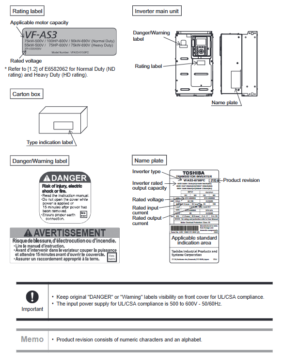
The product strictly limits its application boundaries and cannot be used in scenarios that have a significant impact on public safety or require special quality control, such as power plants, railways, nuclear power, aerospace, life support, surgical equipment, etc. It is only suitable for motor speed regulation needs in general industrial production. The model naming follows a unified rule, for example, in "VFAS3-6750PC", "VFAS3" is the series identifier, "6" represents the voltage level covering 500V-690V, "750" corresponds to the core capacity code, "P" represents the equipped operation panel, and "C" represents the built-in EMC filter.
Core specifications and performance parameters
(1) Voltage and power coverage range
This series is divided into three categories based on voltage levels, each supporting HD (Heavy Duty, constant torque) and ND (Normal Duty, variable torque) rated modes, adapted to different load characteristics:
Voltage level HD rated mode (constant torque) ND rated mode (variable torque) Capacity labeling Unit Core model example
500V class 1.5kW - 55kW 2.2kW - 75kW kW VFAS3-6022PC(1.5kW)、VFAS3-6750PC(55kW)
600V(575V) class 2HP - 75HP 3HP - 100HP HP VFAS3-6022PC(2HP)、VFAS3-6750PC(75HP)
690V class 2.2kW - 75kW 3kW - 90kW kW VFAS3-6022PC(2.2kW)、VFAS3-6750PC(75kW)
(2) Key performance indicators
1. Control core parameters
Control method: Adopting sine wave PWM control, the output waveform is stable, reducing motor operating losses
Output frequency: Set range from 0.01Hz to 590Hz, default operating range from 0.01Hz to 60Hz, meeting the requirements of low-speed precise control and high-speed operation
Frequency accuracy: ± 0.01% ± 0.022Hz in digital input mode, ± 0.2% in analog input mode (25 ± 10 ℃ environment), industry-leading control accuracy
Frequency resolution: Input 0.1Hz on the operation panel, 0.01Hz for communication commands, and 1/2000 of the highest frequency for analog input (0.03Hz at 60Hz)
Carrier frequency: A1Y base (small capacity model) 1.0kHz -6.0kHz, A2Y base (large capacity model) 1.0kHz -4.9kHz, both default to 2.5kHz, adjustable according to noise and heat dissipation requirements
2. Overload and operational capacity
HD rated mode: 150% overload for 60 seconds, suitable for constant torque loads (such as conveyors, cranes, compressors)
ND rated mode: 120% overload for 60 seconds, suitable for variable torque loads (such as fans, pumps, blowers)
Acceleration/deceleration time: adjustable from 0.01 seconds to 6000 seconds, supporting 4 sets of acceleration/deceleration curve switching, including S-shaped acceleration/deceleration mode to avoid load impact
3. Physical and environmental parameters
Machine base specifications: divided into two categories: A1Y (VFAS3-6022PC~6220PC) and A2Y (VFAS3-6300PC~6750PC), with a weight range of 21.6kg to 57kg
Protection level: IP00 (IEC60529 standard), shell color RAL7016 (dark gray)
Cooling method: forced air cooling, built-in cooling fan designed for a lifespan of 8 years, requiring regular inspection and maintenance
Environmental adaptability:
Working temperature: -15 ℃~+60 ℃ (when the ambient temperature is greater than 50 ℃, it needs to be operated at reduced capacity)
Relative humidity: 5% -95% (without condensation)
Working altitude: ≤ 2000m (when exceeding 1000m, the rated current will decrease by 1% for every 100m increase)
Anti vibration: ≤ 5.9m/s ² (0.6G), frequency range 10Hz-55Hz
Detailed explanation of core functions and configurations
(1) Control mode and operational functions
1. Diversified control modes
V/f control: supports constant V/f, variable torque V/f, automatic torque boosting, 5-point arbitrary V/f curve setting, adapted to different motor characteristics
Advanced control: Built in vector control, PID control, torque control, supporting torque limitation and torque command input (-10V~+10Vdc)
Special functions: light load high-speed operation (improves motor efficiency under light load), droop function (load balancing when multiple inverters drive the same load), frequency jump (can set 3 jump frequencies to avoid resonance)
2. Run operational functions
Basic operation: forward and reverse control, jog operation (panel or terminal control), coast stop and emergency stop control
Preset speed: 31 preset speeds can be switched through a combination of 5 terminals, supporting quick switching between different working conditions
Automatic functions: automatic acceleration and deceleration, automatic torque increase, regenerative energy suppression control, reducing the difficulty of manual debugging
Fault handling: Supports 10 automatic retry functions, with an adjustable retry waiting time of 0-10 seconds, and fault records can be retained
(2) Interface and Communication System
1. Digital interface
Digital input: 14 programmable terminals (including 6 optional extensions), supporting 204 function assignments, compatible with positive/negative logic, compliant with IEC61131-2 logic type 1
Digital output: 3 programmable terminals (including 2 optional extensions), output capacity 24Vdc/50mA, supporting 262 function assignments
Pulse interface: The digital input terminal [S4] [S5] can receive pulse frequency signals (up to 30kbps), and the digital output terminal [FP] can output pulse signals (up to 30kbps, with a duty cycle of 50%)
2. Simulation interface
Analog input: 5 frequency command inputs (including 2 optional extensions), supporting signal types such as 0~10V, -10V~+10V, 4~20mA, etc. The input impedances are 31.5k Ω (voltage signal) and 250 Ω (current signal), respectively
Analog output: 2 programmable terminals, supporting 0~10V, 0~20mA, 4~20mA outputs, can allocate 54 monitoring parameters (such as frequency, current, voltage)
3. Communication capability
Built in interface:
Ethernet (dual port with switch): Supports EtherNet/IP, Modbus TCP, Webserver, enabling remote monitoring and control
RS485 (2 channels): Supports Toshiba inverter specific protocol Modbus RTU, Adapt to industrial bus networking
Optional extension protocols: PROFINET, DeviceNet, PROFIBUS DP, EtherCAT, CANopen, compatible with mainstream industrial control systems
(3) Security and protection functions
1. Core security design
Safe Torque Off (STO): Compliant with IEC61800-5-2 standard, cutting off the motor torque output does not affect the power supply of the control circuit, ensuring the safety of personnel and equipment
Insulation protection: Built in grounding detection function to avoid the risk of electric shock caused by poor grounding
Operation safety: It is forbidden to disassemble the front cover during operation. When disassembling the front cover and front small cover, the power must be turned off and the capacitor discharge must be confirmed to be completed
2. Comprehensive protection function
Specific functions of protection types
Electrical protection for overcurrent, overvoltage, undervoltage, short circuit (load side), ground fault (load side), input phase loss, output phase loss
Thermal protection for frequency converter overload, motor overload (electronic thermal protection), brake resistor overload, and frequency converter overheating
Mechanical protection stall prevention (during operation/acceleration), over torque protection
Other protective power sources include instantaneous power outages (≥ 15ms), EEPROM failures, RAM failures, and communication errors
Installation and wiring specifications
(1) Installation requirements
1. Installation foundation and space
Installation carrier: It must be fixed on a metal plate and used to assist in heat dissipation. It is prohibited to install it on flammable materials or non-metallic surfaces
Installation space:
Single installation: Reserve ≥ 10cm vertically and ≥ 5cm horizontally
Multiple parallel installations: distance between adjacent inverters ≥ 11mm to avoid hot air backflow
Environmental requirements: Install indoors, away from direct sunlight, corrosive gases, oil mist, metal dust, and avoid locations with severe vibrations
2. Handling and fixing
Transportation specifications: Models weighing ≤ 20kg can be transported by a single person, while models weighing > 20kg require cooperation from two people; VFAS3-6300PC~6750PC (A2Y machine base) needs to be transported by a crane and lifted through the top lifting hole. It is forbidden to grip the front cover or wiring hole during transportation
Fixing method: M5 (A1Y machine base) or M8 (A2Y machine base) screws are used for fixing, with tightening torques of 2.6N · m and 11.8N · m respectively, to ensure a firm installation
(2) Wiring specifications
1. Preparation before wiring
Power off requirement: Before wiring, all input power must be cut off, wait for at least 15 minutes, confirm that the charging light is off, and use a tester with a range of 1400Vdc or above to test the DC main circuit (between PA/+and PC/-) voltage to ensure it is ≤ 45V before operation
Personnel qualifications: Wiring work must be completed by electricians with professional qualifications to avoid accidents caused by incorrect wiring
2. Core wiring requirements
Power wiring: Connect the 3-phase power supply to the [R/L1], [S/L2], and [T/L3] terminals, and the voltage fluctuation should be within the range of -15% to+10% of the rated voltage (± 10% when operating at full load)
Motor wiring: Connect the 3-phase winding of the motor to the [U/T1], [V/T2], and [W/T3] terminals, and ensure that the phase sequence is correct to avoid motor reversal; It is strictly prohibited to directly connect the power supply to the output terminal
Grounding Wiring: The grounding wire must be connected to the [PE] terminal, with specifications not lower than the input/output wire, using a separate grounding method. It is prohibited to share the grounding terminal with the chassis screws or other equipment. The grounding resistance must comply with local electrical standards
Braking resistor wiring: It can only be connected to the [PA/+] and [PB] terminals, and is strictly prohibited from being connected between [PA/+] and [PC/-] to avoid short circuits and fires
Control wire wiring: Shielded wire (cross-sectional area ≥ 0.75mm ²) should be used for the control wire, which should be wired separately from the power wire (spacing ≥ 10cm) to avoid electromagnetic interference; The tightening torque of the terminal screw should comply with the specifications (control terminal about 1.2N · m)
3. Peripheral device configuration
Must be configured:
Short circuit protection device: Molded case circuit breaker (MCCB) or earth leakage circuit breaker (ELCB), installed on the input side of the inverter
Emergency stop device: It needs to be linked with the system and can be stopped by cutting off the power or controlling the signal
Recommended configuration:
Thermal relay (THR): When multiple motors share one inverter, each motor needs to be configured separately
Input reactor: suppresses harmonic interference and improves power factor on the power supply side
Surge absorber: The magnetic contactor (MC) coil side needs to be installed to avoid damage to components caused by surge voltage

Parameter Setting and Operation Guide
(1) Core parameter configuration
1. Basic parameters
Multiple Rating Selection (AUL): The default setting is 600V (575V) HD mode, which can be used to switch voltage levels and rated modes (such as 14=500V ND, 17=690V HD)
Command Selection (CMOd): Terminal control, panel control, Ethernet control, RS485 control, etc. can be selected
Frequency Command Selection (FMOd): Analog input, panel touch wheel, communication command, pulse input, etc. can be selected
Acceleration/deceleration time (ACC/DEC): default 10.0 seconds, adjustable according to load characteristics to avoid start/stop impact
2. Protect parameters
Motor overload protection current (tHrA): set according to the rated current of the motor, with a default value of random capacity variation
Stall prevention level (F601/F185): The default value should be higher than the motor no-load current to avoid frequent triggering of stall protection
Overheating protection: Built in temperature sensor, detects the internal temperature of the inverter, automatically reduces capacity or shuts down when overheating occurs
3. Regional adaptation parameters
Regional settings: Supports parameter presets for 5 regions including Japan, North America, Asia, Europe, and China, covering adaptation values such as frequency and voltage
Basic frequency voltage (vLv/F171, etc.): Different voltage levels correspond to different preset values (e.g. 500V class is 500V, 690V class is 690V)
(2) Operation panel usage
Display function: LCD/LED display screen can display output frequency, current, voltage, torque, fault codes, parameter values, etc., supporting multilingual switching
Monitoring function: It can monitor more than 20 operating parameters in real time, including cumulative operating time, motor overload coefficient, and fault history (including recent multiple fault records)
Parameter operation: supports parameter upload/download, user default parameter saving, parameter reset to factory settings, and can be locked with a password to prevent accidental operation
Applicable scenarios and application value
(1) Core applicable scenarios
Constant torque load scenarios: conveyors, cranes, mixers, compressors, machine tools, etc., adapted to HD rated mode
Variable torque load scenarios: centrifugal fans, centrifugal pumps, blowers, etc., adapted to ND rated mode, with significant energy-saving effects
Precise control scenario: equipment that requires stable speed and precise torque control (such as precision machine tools and packaging machinery)
Distributed control scenario: supports multi protocol communication, can be connected to factory MES system and SCADA system, suitable for automated production lines
(2) Core application value
Strong adaptability: wide voltage and power coverage, dual rated mode switching, compatible with multiple motor types, meeting the needs of different industrial scenarios
Precise control: high frequency accuracy and resolution, multiple control modes to choose from, ensuring equipment stability and product quality
Safe and reliable: With comprehensive safety protection functions and STO safety design, it reduces equipment failures and personnel safety risks
Convenient operation and maintenance: rich monitoring functions, fault recording, and parameter locking, simplifying debugging and maintenance processes
Energy saving and efficient: Reduce load idle losses through precise speed regulation, especially suitable for fan and pump loads, with an energy-saving rate of up to 20%~50%
Precautions and usage restrictions
Power compatibility: cannot be connected to the corner grounding system power supply, the IT system power supply needs to disconnect the grounding capacitor; The power supply voltage must strictly match the rated voltage of the model
Environmental restrictions: It is prohibited to use in environments with flammable, explosive, corrosive gases, and excessive dust to avoid equipment damage or safety accidents
Wiring taboos: It is strictly prohibited to connect the power supply to the output terminal, connect the brake resistor to the wrong terminal, or mix the control line and power line, otherwise it may cause the inverter to burn out or be electrocuted
Operation taboo: Do not control the start and stop of the inverter through the on/off of the input side magnetic contactor. Frequent operation may damage the capacitor and switching elements
Disposal requirements: When disposing of the inverter, it should be treated according to local environmental standards, especially paying attention to the environmentally friendly disposal of built-in capacitors and cooling fans, to avoid polluting the environment
- OMRON
- ABB
- General Electric
- EMERSON
- Honeywell
- HIMA
- ALSTOM
- Rolls-Royce
- MOTOROLA
- Rockwell
- Siemens
- Woodward
- YOKOGAWA
- FOXBORO
- KOLLMORGEN
- MOOG
- KB
- YAMAHA
- BENDER
- TEKTRONIX
- Westinghouse
- AMAT
- AB
- XYCOM
- Yaskawa
- B&R
- Schneider
- KONGSBERG
- NI
- WATLOW
- ProSoft
- SEW
- ADVANCED
- Reliance
- TRICONEX
- METSO
- MAN
- Advantest
- STUDER
- DANAHER MOTION
- Bently
- Galil
- EATON
- MOLEX
- DEIF
- B&W
- ZYGO
- Aerotech
- DANFOSS
- Beijer
- Moxa
- Rexroth
- Johnson
- WAGO
- TOSHIBA
- BMCM
- SMC
- HITACHI
- HIRSCHMANN
- Application field
- XP POWER
- CTI
- TRICON
- STOBER
- Thinklogical
- Horner Automation
- Meggitt
- Fanuc
- Baldor
- SHINKAWA
- Other Brands
- UniOP
- KUKA
- Iba
- Beckhoff
-
 Basler DECS-200-2L Digital Excitation Control
 -
 Basler BE1-47N Voltage Phase Sequence Relay
 -
 Basler AEC63-7 Analog Excitation Controller 220-277V
 -
 Basler BE1-50/51B-107 Overcurrent Relay
 -
 Basler Electric BE1‑32R BE1‑E1P‑BON0F Protective Relay
 -
 Basler BE1-25 Solid State Time Overcurrent Relay M1EA6PA5S1F
 -
 Basler MVC 232 Manual Voltage Control Module 90 37000 103 60VAC 55VDC
 -
 Basler RAL6144-16GM Racer GigE Line Scan Camera
 -
 Basler SSR 63-12 Static Voltage Regulator
 -
 Basler BE1-51A Overcurrent Relay
 -
 Basler BE1-87T Solid State Protective Relay
 -
 Basler SR4A2B01B3A Static Voltage Regulator
 -
 Basler SSR 32-12 Static Voltage Regulator
 -
 Basler TRR00696 Transformer 1KVA 115V
 -
 Basler DECS-100-B15 AVR Replacement
 -
Basler BE1-27 Under-Voltage Relay
-
 Basler ACA2000-50GM Interface Module
 -
 Basler AEC63-7 Analog Excitation Controller
 -
 Basler PRS 250 Veri-Sync Relay
 -
 Basler SR4A-2B15B3A Static Voltage Regulator
 -
Basler BE1-32R Power Relay
-
Basler SR8A-2B06B3E Static Voltage Regulator
-
Basler BE1-81 O/U Frequency Relay
-
 Basler BE1-51A-K2E-W6M-B1N0F Overcurrent Relay
 -
Basler BE1-851 Overcurrent Relay G3A1S1 – 48-125V AC/DC
-
 Basler BEI-51 Overcurrent Relay – NSN 5945-01-293-2363
 -
Basler Electric L301KC Protective Relay – L301KC
-
 Basler DECS-100-B15 Automatic Voltage Regulator – Generator AVR
 -
 Basler SR4A-2B15B3A Static Voltage Regulator – SR4A2B15B3A
 -
 Basler UF 312 Under Frequency Protective Module – 9094700100
 -
Basler Electric MVC 232 Manual Control Module – 60VAC 55VDC 20A
-
Basler PRS 250 Veri-Sync Relay – Generator Synchronizing Relay
-
 Basler DECS-100-A05 Digital Regulator Review
 -
 Basler AEM-2020 Analog Expansion Module Specs
 -
 Basler DECS-100-B15 Digital Excitation Specs
 -
Basler Electric 9125600106 Regulator Component
-
Basler BE1-51A-K1E-W6M-B1N0F Overcurrent Relay
-
 Basler MVC-301 MVC 300 Excitation Controller
 -
 Basler SSR 32-12 Static Voltage Regulator
 -
 Basler 9-2849-00-101 Control Module
 -
Basler BE1-51A Overcurrent Relay
-
 Basler BE1-51/27R Overcurrent Relay
 -
 Basler BE1-51 Overcurrent Relay
 -
 Basler SR8A-2B15B3A Static Voltage Regulator
 -
 Basler BE32965001 Transformer and Timer Board
 -
 Basler 9174700100 EL200-7 Excitation Limiter
 -
 Basler BE2000E AVR Voltage Regulator
 -
Basler BE1-87G Differential Relay
-
 Basler BE21834001 Generator Control Module
 -
Basler DECS-100-B15 AVR
-
 Basler D90 96801 100 PCB Card
 -
 Basler XR2002F Voltage Regulator (110 VAC, 48-480 Hz)
 -
 Basler SR8A-2B14B3A Regulator
 -
 Basler 9561500100 Module
 -
 Basler DECS-400 BE1-11 System
 -
 Basler DECS-100-B15 Excitation Control
 -
 Basler SCP 210 Frequency Controller
 -
Basler SR4A-2B15B3A Static Voltage Regulator
-
Basler BE1-32R Power Relay
-
 Basler PIA2400-17GM Power Interface Adapter
 -
 Basler MVC 232 Manual Voltage Control Module
 -
 Basler SSR 32-12 Static Voltage Regulator
 -
Basler 5MW AVR Generator Voltage Regulator
-
 Basler VR63-4B Voltage Regulator
 -
Basler DECS-100-A05 AVR for Engine Generator
-
Basler DECS-100-B15 Automatic Voltage Regulator
-
Basler BE1-32R Directional Power Relay
-
Basler BE1-87B Differential Relay
-
 Basler UFOV 260A Protective Module
 -
 Basler 9-2614-02-100 PCB Rev M
 -
Basler DECS-100-B15 Digital AVR
-
 Basler 9284900103 PS DECS-400N
 -
 Basler D4N3H1U Intertie Protection
 -
 Basler DECS-100-B15 A15 AVR
 -
 Basler KR4F Voltage Regulator
 -
 Basler BE26434 T14 Transformer
 -
 Basler SR8A-2B15B3A Regulator
 -
 Westinghouse 774B472A12 AR Relay
 -
Basler DECS-100-B15 AVR
-
Basler XR2002F Regulator 110V
-
Basler SR125-E Static Regulator
-
Basler SSR 125-12 Regulator
-
Basler MOC2599 Motor Pot
-
 Basler BE1-DFPR Feeder Relay
 -
 Basler CBS 305 Current Boost
 -
Basler BE1-25 AutoSync
-
Basler MVC 300 Voltage Control
-
 Basler BE3-25A AutoSync
 -
 Basler KR7FF Static Regulator
 -
Basler 90-49000-100 Regulator
-
 Basler 880 kVA Dry Type Transformer Specs
 -
Basler Electric BE1-25 Sync-Check Relay Specs
-
 Basler SSR 125-12 Voltage Regulator Specs
 -
 Basler Electric BE1-851 Overcurrent Relay Review
 -
Basler Electric 149D930G02 Control Sub-Assembly
-
 Basler Electric BE1-81O/UT Frequency Relay Specs
 -
 Basler Electric BE1-51/27C Overcurrent Relay
 -
 Basler Electric 149D956G02 Industrial Component
 -
Basler Electric BE1-51A Overcurrent Relay Specs
-
 Basler Electric BE1-40Q Loss of Excitation Relay
 -
Basler DECS-200 Excitation Control System
-
 Basler DECS-200 Voltage Regulator 56-277V AC / 125V DC
 -
Basler BE1-87T Transformer Differential Relay
-
 Basler RDP-110-S1 Protection Relay
 -
 Basler BE1-700V Digital Protective Relay
 -
 Basler BE1-951 Overcurrent Protection System
 -
 Basler DECS-300 Digital Excitation Control
 -
 Basler DECS-200 Digital Excitation Control
 -
 Basler DECS-200-1C Excitation Control System
 -
Basler DECS-200-1L Digital Excitation Control
-
 Basler Electric BE1-GPS Generator Protection System
 -
Basler Electric DECS-200-1C Digital Excitation Controller
-
 Basler Electric DECS125-15 Excitation Control with Power Module
 -
Basler Electric BE1-87G Differential Relay
-
 Basler Electric BE1-11 Protection System I5A3M2P2N0EA00
 -
Basler Electric DECS-200-1C Excitation Control System
-
Basler Electric BE1-11g Generator Protection Relay
-
Basler Electric DECS 125-15-B2C1 V2.0.9 Excitation Control
-
Basler Electric BE1-81O/UT3ED1JA7N2F Frequency Relay
-
Basler Electric BE1-81O/UT3EE1YB7N1F Frequency Relay
-
 Basler Electric DECS-200-1L Digital Excitation Control System
 -
Basler DECS125-15-B2C1 Excitation Control
-
 Basler 9507900205 SSR Retrofit Voltage Regulator
 -
 Basler BE2000E Digital Voltage Regulator
 -
 Basler BE1-GPS Generator Protection System
 -
Basler DECS-250-CN1CN1N Digital Excitation Control
-
 Basler DGC-2020 Genset Controller
 -
Basler BE1-81O UT3ED1LA7N0F Frequency Relay (Variant)


