
TOSHIBA VF-S15 frequency converter
Example of input voltage level frequency converter model
Single phase 200V-240V VFS52S-2002PL__/- W1/Y-A *, VFS52S-2004PL__/- W1/Y-A*
Three phase 200V-240V VFS15-2002PM_/- W1/Y-A *, VFS15-2004PM_/- W1/Y-A*
Three phase 380V-500V VFS15-4004PL_/- W1/Y-A *, VFS15-4007PL_/- W1/Y-A*
Three phase 525V-600V VFS15-6015P_/- W1/Y-A *, VFS15-6022P_/- W1/Y-A*
TOSHIBA VF-S15 frequency converter
Basic information of the document
Scope of Application
The document specifically lists the applicable models (including multiple voltage levels) for the Toshiba VF-S15 series frequency converter, as shown in the table below. Models marked with suffixes such as "Y-A38" and "Y-A65" are not applicable.
Example of input voltage level frequency converter model
Single phase 200V-240V VFS52S-2002PL__/- W1/Y-A *, VFS52S-2004PL__/- W1/Y-A*
Three phase 200V-240V VFS15-2002PM_/- W1/Y-A *, VFS15-2004PM_/- W1/Y-A*
Three phase 380V-500V VFS15-4004PL_/- W1/Y-A *, VFS15-4007PL_/- W1/Y-A*
Three phase 525V-600V VFS15-6015P_/- W1/Y-A *, VFS15-6022P_/- W1/Y-A*
Safety warnings and personnel qualifications
1. Warning system
The document categorizes safety warnings into two types, specifying risk levels and response requirements:
Warning type meaning Typical scenarios
Warning operation errors may result in death or serious injury. Touching live cables, repairing without discharge, and short circuiting DC bus capacitors
Incorrect operation of the solution may result in minor injuries or equipment damage, voltage incompatibility, capacitor aging, and performance degradation
2. Core security taboos (Warning level)
Do not touch live cables (such as printed circuit boards) inside the frequency converter, and use insulated tools;
Before maintenance, it is necessary to follow the process of "power off → paste the prohibition closing label → lock the power-off switch → wait for 15 minutes to discharge → measure the DC bus voltage<42V";
Do not short-circuit PA/+and PC/- terminals or DC bus capacitors;
Before powering on, all cover plates must be installed and closed.
3. Personnel qualification requirements
Only qualified personnel are allowed to operate (subject to the following conditions):
Having received safety training, able to identify and mitigate risks;
Familiar with this manual and product documentation, proficient in electrical/mechanical system knowledge;
Understand international/national electrical codes and accident prevention regulations.
Detailed explanation of core security functions
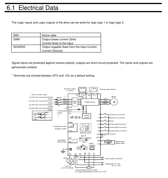
1. STO (Safe Torque Off)
Function definition: To put the motor into a torque free state (prohibiting motor start or free stop), cut off the energy supply to the motor, corresponding to IEC 60204-1 stop category 0 (uncontrolled stop).
**According to * *: IEC 61800-5-2 § 4.2.2.2, it should be noted that additional mechanical brakes are required for suspended load scenarios, and electronic components cannot replace anti electric shock isolation measures.
Security level:
Configuration method SIL (IEC 61508) PL (ISO 13849-1) EN 954-1 category
With/without Preventa module SIL 2 PL d 3
Key parameters: response time<10ms, logic input 0<2V, 1>17V, impedance 1.5k Ω.
Module requirements: Mechanical applications (compliant with IEC 60204-1) require mandatory use of Preventa modules (such as XPS AF) to prevent accidental restarts; Use as needed in other scenarios.
2. SS1 (Safe Stop 1, Safety Stop Class 1, Type C)
Function definition: First, slow down the motor according to the specified time delay. After the delay ends, trigger the STO function, corresponding to IEC 60204-1 stop category 1 (control stop).
Normative basis: IEC 61800-5-2 § 4.2.2.2, requires the use of specific safety relays to implement delay logic.
Security level:
Configuration method SIL (IEC 61508) PL (ISO 13849-1) EN 954-1 category
STO+Previnta module (such as XPS AV) SIL 2 PL d 3
Application logic: The deceleration delay time needs to be set according to the actual scenario, and the motor will enter a torque free state after the delay ends.
Compliance standards and safety performance
1. Follow the standards
Specific core requirements for standard categories
IEC 61800 series variable speed electric drive system safety requirements for drive systems
Functional Safety IEC 61508 Ed.2 Electrical/Electronic/Programmable Systems Functional Safety, Defining SIL Levels
Mechanical safety ISO 13849-1/2, EN 954-1 Safety components of mechanical control systems, defining PL levels and categories
Process Safety IEC 62061 Process Industry Safety Instrumented Systems, Distinguishing Global/Component SIL
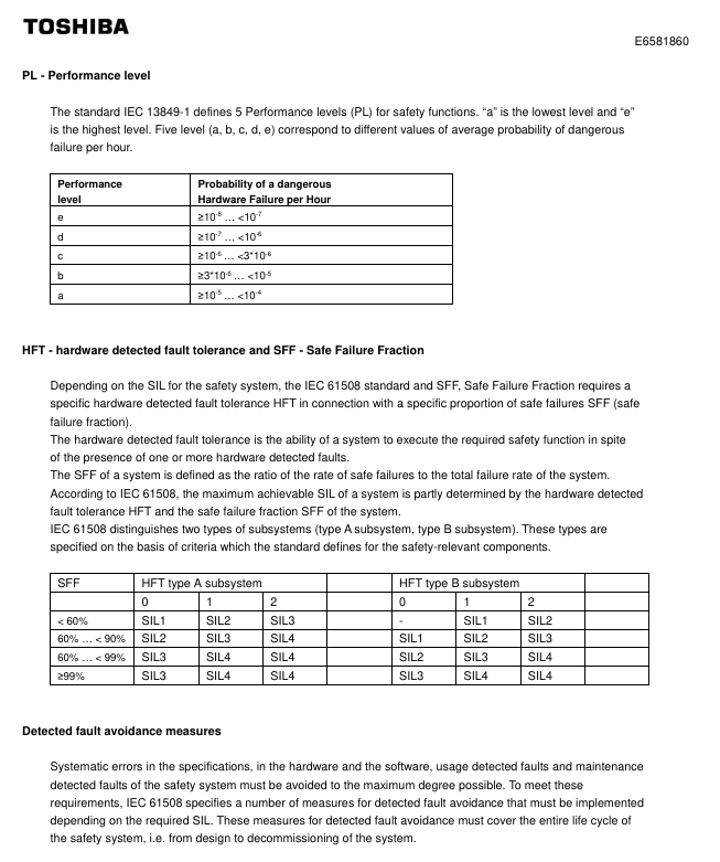
2. Safety performance indicators
Taking the STO function as an example, the key performance parameters are shown in the following table:
Explanation of Indicator Values
SFF (Safety Failure Score) 96.7% represents the proportion of safety failures to total failures, reflecting the safety of the system
MTTFd (Mean Time to Failure) is the average interval between system failures in the year 16200
PFHequ_1y (annual hazard failure probability) 7.04 FIT 1FIT=10 ⁻⁹ times/hour, which means the annual failure probability is extremely low
HFT (Hardware Fault Tolerance) 1 allows one hardware fault to maintain safety functionality
Equipment type B complies with the definition of Class B subsystems in IEC 61508
System architecture and application limitations
1. Authentication architecture (3 types)
The document provides three certified security system architectures, adapted to different application scenarios:
Architecture Type Applicable Scenarios Core Configuration Compliance Standards
- OMRON
- ABB
- General Electric
- EMERSON
- Honeywell
- HIMA
- ALSTOM
- Rolls-Royce
- MOTOROLA
- Rockwell
- Siemens
- Woodward
- YOKOGAWA
- FOXBORO
- KOLLMORGEN
- MOOG
- KB
- YAMAHA
- BENDER
- TEKTRONIX
- Westinghouse
- AMAT
- AB
- XYCOM
- Yaskawa
- B&R
- Schneider
- KONGSBERG
- NI
- WATLOW
- ProSoft
- SEW
- ADVANCED
- Reliance
- TRICONEX
- METSO
- MAN
- Advantest
- STUDER
- DANAHER MOTION
- Bently
- Galil
- EATON
- MOLEX
- DEIF
- B&W
- ZYGO
- Aerotech
- DANFOSS
- Beijer
- Moxa
- Rexroth
- Johnson
- WAGO
- TOSHIBA
- BMCM
- SMC
- HITACHI
- HIRSCHMANN
- Application field
- XP POWER
- CTI
- TRICON
- STOBER
- Thinklogical
- Horner Automation
- Meggitt
- Fanuc
- Baldor
- SHINKAWA
- Other Brands
- UniOP
- KUKA
- Iba
- Beckhoff
-
 Basler BE1-25 Time Overcurrent Relay M1FA6PA4S0F
 -
 Basler SR4A2B05B3E Static Voltage Regulator
 -
 Basler DECS-200-2L Digital Excitation Control
 -
 Basler BE303280001 Control Transformer
 -
 Basler 9262103004 Voltage Regulator Board For Basler DECS-400
 -
 Basler ICRM-7 Inrush Current Reduction Module
 -
 Basler BE1-32R Power Relay
 -
 BASLER ELECTRIC KR4F VOLTAGE REGULATOR 9042600100 600V 50/60Hz
 -
 Basler 9222600101 Power Module
 -
 Basler SR8A-2B15B3A Static Voltage Regulator
 -
 BASLER BE1-87G G1E A1L A0N1P Generator Differential Relay w/ Reactor 9170818100
 -
Basler 9284900101 DECS Power Module
-
 Basler PRS250 Veri-Sync Relay
 -
 Basler BE 12296 001 Transformer
 -
 Basler 905970-104 Rev.M Voltage Regulator
 -
Basler BE1-87T Transformer Differential Relay
-
 Basler SR8A-2B15B3A Static Voltage Regulator
 -
 Basler SR32A2B05B3E Static Voltage Regulator
 -
 Basler SR4A-2B16B3A Static Voltage Regulator
 -
 Basler SR32A-2B13B3E Static Voltage Regulator
 -
 Basler KR4F Voltage Regulator 9042600100
 -
 Basler SSR 32-12 Static Voltage Regulator 400Hz
 -
 Basler CBS 212A Current Boost System
 -
 Basler MVC236 Manual Control Module
 -
Basler UFOV Protective Module 9040000100
-
 Basler SSR 125-12 Static Voltage Regulator
 -
 Basler SR4A2B10A3E Static Voltage Regulator
 -
 Basler BE1-25 Solid State Time Overcurrent Relay
 -
 Basler MVC 232 Manual Voltage Control Module
 -
Basler PRS 250 Veri-Sync Relay
-
 Basler UFOV 260A Under Frequency Over Voltage Relay
 -
 Basler RUL2098-10GC Load Relay
 -
 Basler 9 1049 04 100 PC Board
 -
Basler 125-12 Static Voltage Regulator
-
Basler PRS 250 Veri-Sync Relay
-
Basler 9185900102 SSR 125-12 Regulator
-
Basler BE12819001 Reactor
-
 Teradyne 535-100-00 Power Supply
 -
 Basler BE1-67 Directional OC Relay
 -
 Basler PRP110 Reverse Power Relay
 -
 Basler BE30631001 Isolation Transformer
 -
 Basler DECS-200-2L Digital Excitation Control
 -
 Basler BE1-47N Voltage Phase Sequence Relay
 -
 Basler AEC63-7 Analog Excitation Controller 220-277V
 -
Basler BE1-50/51B-107 Overcurrent Relay
-
 Basler Electric BE1‑32R BE1‑E1P‑BON0F Protective Relay
 -
Basler BE1-25 Solid State Time Overcurrent Relay M1EA6PA5S1F
-
 Basler MVC 232 Manual Voltage Control Module 90 37000 103 60VAC 55VDC
 -
Basler RAL6144-16GM Racer GigE Line Scan Camera
-
Basler SSR 63-12 Static Voltage Regulator
-
 Basler BE1-51A Overcurrent Relay
 -
Basler BE1-87T Solid State Protective Relay
-
Basler SR4A2B01B3A Static Voltage Regulator
-
 Basler SSR 32-12 Static Voltage Regulator
 -
 Basler TRR00696 Transformer 1KVA 115V
 -
 Basler DECS-100-B15 AVR Replacement
 -
Basler BE1-27 Under-Voltage Relay
-
 Basler ACA2000-50GM Interface Module
 -
 Basler AEC63-7 Analog Excitation Controller
 -
Basler PRS 250 Veri-Sync Relay
-
 Basler SR4A-2B15B3A Static Voltage Regulator
 -
Basler BE1-32R Power Relay
-
Basler SR8A-2B06B3E Static Voltage Regulator
-
Basler BE1-81 O/U Frequency Relay
-
 Basler BE1-51A-K2E-W6M-B1N0F Overcurrent Relay
 -
Basler BE1-851 Overcurrent Relay G3A1S1 – 48-125V AC/DC
-
 Basler BEI-51 Overcurrent Relay – NSN 5945-01-293-2363
 -
Basler Electric L301KC Protective Relay – L301KC
-
 Basler DECS-100-B15 Automatic Voltage Regulator – Generator AVR
 -
Basler SR4A-2B15B3A Static Voltage Regulator – SR4A2B15B3A
-
Basler UF 312 Under Frequency Protective Module – 9094700100
-
Basler Electric MVC 232 Manual Control Module – 60VAC 55VDC 20A
-
Basler PRS 250 Veri-Sync Relay – Generator Synchronizing Relay
-
 Basler DECS-100-A05 Digital Regulator Review
 -
 Basler AEM-2020 Analog Expansion Module Specs
 -
 Basler DECS-100-B15 Digital Excitation Specs
 -
Basler Electric 9125600106 Regulator Component
-
Basler BE1-51A-K1E-W6M-B1N0F Overcurrent Relay
-
 Basler MVC-301 MVC 300 Excitation Controller
 -
Basler SSR 32-12 Static Voltage Regulator
-
Basler 9-2849-00-101 Control Module
-
Basler BE1-51A Overcurrent Relay
-
 Basler BE1-51/27R Overcurrent Relay
 -
 Basler BE1-51 Overcurrent Relay
 -
 Basler SR8A-2B15B3A Static Voltage Regulator
 -
 Basler BE32965001 Transformer and Timer Board
 -
 Basler 9174700100 EL200-7 Excitation Limiter
 -
 Basler BE2000E AVR Voltage Regulator
 -
Basler BE1-87G Differential Relay
-
 Basler BE21834001 Generator Control Module
 -
Basler DECS-100-B15 AVR
-
 Basler D90 96801 100 PCB Card
 -
 Basler XR2002F Voltage Regulator (110 VAC, 48-480 Hz)
 -
 Basler SR8A-2B14B3A Regulator
 -
 Basler 9561500100 Module
 -
 Basler DECS-400 BE1-11 System
 -
 Basler DECS-100-B15 Excitation Control
 -
Basler SCP 210 Frequency Controller
-
Basler SR4A-2B15B3A Static Voltage Regulator
-
Basler BE1-32R Power Relay
-
 Basler PIA2400-17GM Power Interface Adapter
 -
 Basler MVC 232 Manual Voltage Control Module
 -
Basler SSR 32-12 Static Voltage Regulator
-
Basler 5MW AVR Generator Voltage Regulator
-
 Basler VR63-4B Voltage Regulator
 -
Basler DECS-100-A05 AVR for Engine Generator
-
Basler DECS-100-B15 Automatic Voltage Regulator
-
Basler BE1-32R Directional Power Relay
-
Basler BE1-87B Differential Relay
-
 Basler UFOV 260A Protective Module
 -
 Basler 9-2614-02-100 PCB Rev M
 -
Basler DECS-100-B15 Digital AVR
-
 Basler 9284900103 PS DECS-400N
 -
 Basler D4N3H1U Intertie Protection
 -
 Basler DECS-100-B15 A15 AVR
 -
 Basler KR4F Voltage Regulator
 -
 Basler BE26434 T14 Transformer
 -
 Basler SR8A-2B15B3A Regulator
 -
 Westinghouse 774B472A12 AR Relay
 -
Basler DECS-100-B15 AVR
-
Basler XR2002F Regulator 110V
-
Basler SR125-E Static Regulator
-
Basler SSR 125-12 Regulator
-
Basler MOC2599 Motor Pot
-
 Basler BE1-DFPR Feeder Relay
 -
 Basler CBS 305 Current Boost
 -
Basler BE1-25 AutoSync
-
Basler MVC 300 Voltage Control


