
WESTINGHOUSE iGen5000 Digital Inverter Generator
WESTINGHOUSE iGen5000 Digital Inverter Generator
Brand positioning and core product values
Westinghouse, as a globally renowned power equipment brand, has launched the iGen5000 digital inverter generator with the core positioning of "high performance, high reliability, easy operation, and multi scenario adaptation". It is a portable power generation device designed specifically for outdoor operations, emergency power supply, RV camping, small projects, and other scenarios. With a strong output of 3900W rated power and 5000W peak power, combined with digital inverter technology and permanent magnet generator design, the product achieves a low total harmonic distortion of ≤ 3%, and its power supply stability is comparable to that of mains power. It can safely drive voltage sensitive equipment such as computers, refrigerators, and air conditioners. Its core value lies in balancing power output and usage costs through "triple start mode, ECO energy-saving mode, and parallel expansion function". At the same time, with multiple safety protections and global certification qualifications (EPA, UL, cUL, CE, RoHS), it has become the preferred solution for home emergency, outdoor operations, and commercial backup power.
Overview of Product Core Technical Parameters
(1) Basic electrical parameters
Power and voltage characteristics:
Rated operating power: 3900W; peak power: 5000W.
Rated voltage: 120V; frequency: 60Hz; phase: single-phase.
Total harmonic distortion (THD): ≤ 3%, pure power supply, suitable for sensitive electronic devices.
Power configuration:
Engine displacement: 224cc; Spark plug model: 97109-F7RTC; Spark plug clearance: 0.60-0.80mm.
Inlet valve clearance: 0.08-0.12mm; exhaust valve clearance: 0.13-0.17mm.
Voltage regulator: digital; AC generator type: permanent magnet type, with higher power generation efficiency.
Fuel and Capacity:
Fuel type: 87-93 unleaded gasoline (ethanol content ≤ 10%, E15/E85 prohibited).
Fuel tank capacity: 3.4 gallons (12.8 liters); Oil capacity: 0.63 US quarts (0.60 liters); Recommended engine oil model: 10W-30 (5W-30 or 10W-40 can be used for extreme temperatures).
Startup mode: Supports remote start (up to 30 meters), electric start, and manual start (Recoil) triple start, suitable for different usage scenarios.
(2) Physical and environmental parameters
Protection and certification: Protection level IP20/NEMA 1, compliant with EPA, UL, cUL, CE, RoHS certification standards.
Size and weight:
Equipped with a retractable handle and transport wheel, it can be pushed by a single person; Double person carrying handle design, convenient for short distance movement.
The weight is about 50-60 pounds (due to slight differences in configuration), the size is compact, and it does not take up too much storage space.
Environmental adaptability:
Working temperature: -10 ℃~+50 ℃ (short-term tolerance -15 ℃~+50 ℃); Storage temperature: -20 ℃~+70 ℃.
Humidity requirement: ≤ 95% RH (no condensation); Maximum ambient temperature: 40 ℃ (104 ° F).
High altitude adaptability: For every 1000 feet (305 meters) increase in altitude, the power output decreases by about 3.5%. For altitudes exceeding 2000 feet (762 meters), a high-altitude carburetor kit (Part # 518913-01) needs to be installed.
Detailed explanation of core functional features
(1) Power Control and Operation Mode
1. Flexible start-up and operation adjustment
Triple start mode:
Remote start: equipped with a wireless remote key, with an effective distance of up to 99 feet (30 meters), no need for close range operation, suitable for emergency scenarios.
Electric start: One click press start, easy to operate, relying on the built-in 12V battery (model 511019) for power supply.
Hand pulled start: Mechanical backup start method, no battery dependence, ensuring that it can still start in extreme situations.
ECO energy-saving mode:
Core principle: Automatically adjust the engine speed according to the load size, reduce the speed when the load is light, and reduce fuel consumption and noise.
Applicable scenarios: Drive continuous light load devices such as computers, lighting fixtures, and mobile phone chargers to extend battery life.
Disabled scenario: When operating in parallel or driving high starting current devices such as air conditioners and water pumps, the ECO mode should be turned off to avoid delayed speed response.
2. Capacity expansion and power management
Parallel operation function: Two generators of the same model can be connected through a dedicated parallel cable (Westinghouse 507PC, purchased separately) to double the total power and meet larger load requirements (such as simultaneously driving multiple high-power devices).
Intelligent power allocation: supports the "high power priority" load access logic. It is recommended to connect the maximum load first after startup, and then add other loads in sequence after the standby motor stabilizes to avoid overload triggering protection.
(2) Operation and display interface
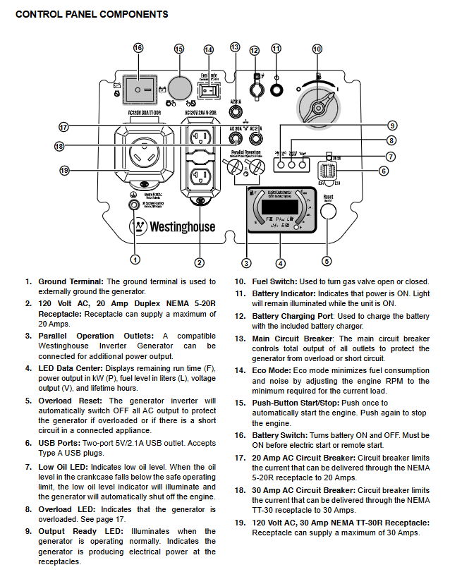
Core configuration of control panel:
Output interfaces: 120V 20A NEMA 5-20R dual socket (2), 120V 30A NEMA TT-30R socket (1), dual USB 5V/2.1A interface, to meet the simultaneous power supply of multiple devices.
Display system: LED digital data center, real-time display of remaining operating time, output power (kW), fuel level (liters), output voltage, and cumulative operating hours, with clear status at a glance.
Control buttons: One click start/stop, ECO mode switch, overload reset button, battery switch. The operation logic is clear and easy for beginners to learn.
Convenient design:
Scalable metal handle+large-sized rubber wheels, easy to move by one person, suitable for outdoor complex terrain.
The fuselage is equipped with independent openings such as fuel filling port, oil filling port, battery inspection cover, etc., and maintenance operations do not require disassembling the entire components.
Safety standards and protection mechanisms
(1) Core safety usage requirements
Usage environment restrictions:
It is strictly prohibited to use it indoors, in garages, basements, crawl spaces, and other enclosed/semi enclosed spaces. It can only be operated outdoors in ventilated areas and must be kept at least 5 feet (1.5 meters) away from doors, windows, and ventilation openings to avoid carbon monoxide poisoning.
Do not use in humid environments (rainy, snowy, or waterlogged areas) to avoid short circuits and electric shocks caused by moisture; Keep hands dry and wear insulated gloves during operation.
A ventilation gap of ≥ 5 feet (1.5 meters) should be reserved around the equipment, away from combustibles (hay, wood, gasoline barrels, etc.), and the exhaust port should face unmanned areas to avoid high temperature exhaust gas causing fires or burns.
Fuel safety regulations:
Before refueling, the machine must be stopped and cooled for at least 5 minutes. Smoking or approaching open flames is prohibited; Fuel should not be overfilled, and expansion space should be reserved (up to the red filling ring in the fuel tank).
Fuel must be stored in approved gasoline containers, away from heat and fire sources; If fuel spills, immediately wipe it clean and wait for the area to dry before starting the equipment.
Prohibit the use of gasoline as a cleaning agent, avoid contact between fuel and skin, and wash hands promptly after operation.
(2) Comprehensive protection function
Protection type triggers condition protection action
Overload protection output current exceeds the rated value or load short circuit automatically cuts off all AC outputs, overload LED red light lights up, and the engine continues to run
Low oil level protection: When the oil level in the crankcase is below the safety threshold, the low oil LED yellow light will turn on, and the engine will automatically stop to avoid damage caused by cylinder pulling
Overcurrent/short circuit protection circuit short circuit or branch current exceeding the standard (20A/30A branch) corresponds to automatic tripping of the branch circuit breaker, and the main circuit breaker (31A) is linked for protection
Overvoltage/undervoltage protection: Abnormal output voltage (overvoltage>132V/undervoltage<108V). Digital regulator intervenes in regulation, and in severe cases, the output is cut off
Ground fault protection equipment shell or line grounding abnormality triggers safe power-off, reducing the risk of electric shock
Overheating protection: If the engine or inverter temperature exceeds the safety threshold, it will automatically reduce power or shut down, and can be restored after cooling down
Operation and usage process
(1) First use preparation
Oil filling: The equipment has not been filled with oil before leaving the factory. It is necessary to use the accompanying 10W-30 oil and funnel to fill the level surface between the "L-H" mark on the dipstick to avoid overfilling or underfilling.
Fuel filling: Use 87-93 unleaded gasoline, clean the area around the fuel tank cap before filling, slowly fill to the red filling ring, and tighten the fuel tank cap until you hear a "click" sound.
Battery connection: Open the battery access cover, connect the pre installed quick connector, ensure that the battery strap is securely fastened, and avoid loosening during transportation.
Equipment positioning: Place in a dry, flat, and ventilated outdoor area, away from doors, windows, and flammable materials, and reserve sufficient ventilation gaps.
(2) Startup and operation steps
Pre start check: Confirm that all loads have been disconnected, the oil level is normal, the fuel is sufficient, and the battery switch is in the "ON" position.
Start operation:
Remote start: Press the "ON" button on the remote control for 1 second, and the device will automatically start. Wait for the "output ready" LED green light to turn on before connecting the load.
Electric start: Press the "Start/Stop" button on the control panel for 2 seconds. After the engine starts, wait for 30 seconds until the speed stabilizes.
Hand pulled start: Slowly pull the rope until resistance is felt, then quickly pull again, and release the rope to naturally retract after starting.
Load connection: According to the principle of "high power priority", first connect large loads such as air conditioning and refrigerator, wait for the equipment to stabilize (engine running smoothly), and then connect small loads in sequence, with a total load not exceeding 3900W.
Operation adjustment: In light load scenarios such as phone charging and lighting fixtures, ECO mode can be activated to reduce fuel consumption and noise; In high load scenarios, ECO mode needs to be turned off to ensure power output.
(3) Shutdown and shutdown process
Disconnect all loads and let the equipment run without load for 3-5 minutes to stabilize the internal temperature.
Press the "Start/Stop" button on the control panel for 1 second or the "OFF" button on the remote control for 1 second to shut down the engine.
Turn off the battery switch (if not in use for a long time, disconnect the battery connector), tighten the fuel tank cap, and clean the surface of the equipment with debris.
If stored for a long time, fuel and engine oil should be handled according to the "Storage Specification" (see "Storage Requirements" below for details).
(4) Parallel operation (expansion requirement)
Prepare two compatible Westinghouse iGen5000 generators, ensuring that both have been shut down and the ECO mode is in the "OFF" position.
Use a dedicated parallel cable (Westinghouse 507PC) to connect the parallel interfaces of two devices, ensuring that the left and right cable connections correspond (building power supply needs to be matched, direct power supply can be ignored).
Start one generator first, wait for the "output ready" LED to light up, then start the second one. After both devices are stable, connect the loads in sequence, and the total load should not exceed the sum of the rated power of the two devices (7800W).
When shutting down, all loads should be disconnected first, then the two generators should be shut down in sequence, and finally the parallel cables should be disconnected.
Maintenance and upkeep standards
(1) Regular maintenance cycle and project
Key operational points for core projects in the maintenance cycle
Before each use, check the oil level and place the equipment horizontally. Take out the dipstick and wipe it clean before inserting it (without tightening), and observe that the oil level is between "L-H"
First 25 hours/1 month engine oil change. When the engine is warm, drain the oil, replace the new oil to the dipstick mark, and replace the oil drain bolt washer (Part # 94007)
Every 50 hours/6 months, the cycle of oil change and air filter cleaning in harsh environments (dusty, high temperature) needs to be shortened; Clean the air filter with household detergent, dry it, soak it in oil and squeeze it until there is no excess oil
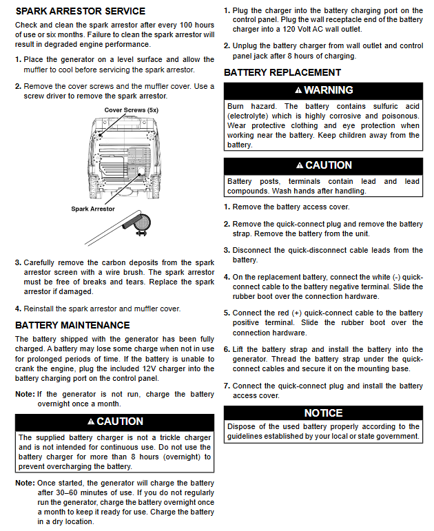
Spark plug maintenance every 100 hours/6 months+spark eliminator cleaning Spark plug cleaning Carbon deposits, check electrode status, adjust gaps if abnormal; Spark eliminator uses a wire brush to clean carbon deposits
Replace spark plug every 300 hours/1 year+replace air filter Replace original spark plug (Part # 97109-F7RTC) and foam air filter (Part # 5691) to ensure smooth air intake
Fuel treatment and battery maintenance before long-term storage, emptying the fuel tank or adding fuel stabilizer, disconnecting the connector after the battery is fully charged, and recharging once a month
(2) Key component maintenance details
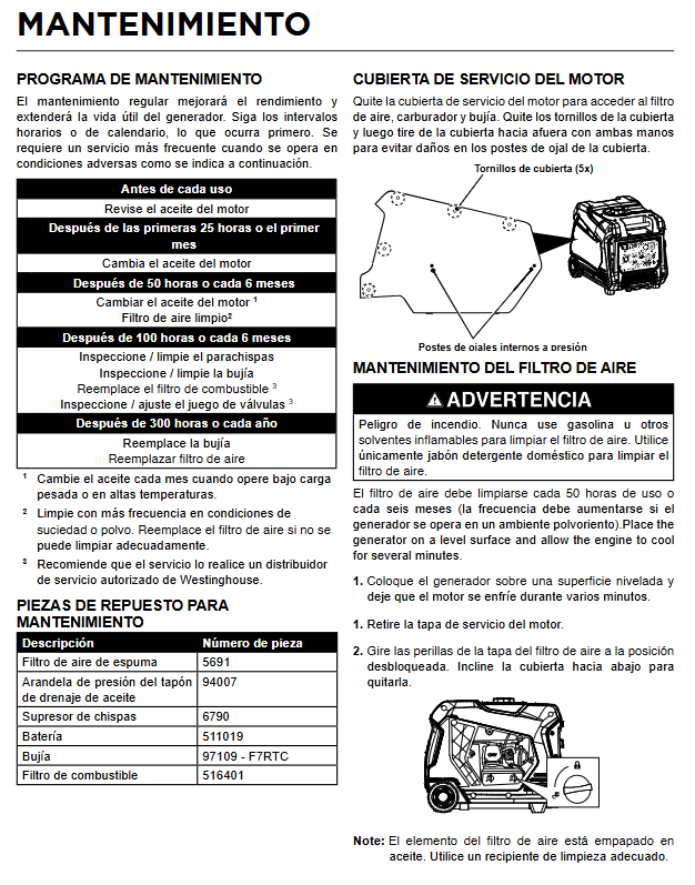
1. Maintenance of air filter
Remove the engine service cover, rotate the air filter box knob to unlock it, take out the foam air filter, soak it in warm water+household detergent for cleaning, slowly squeeze (no twisting) until there is no dirt.
After rinsing with clean water, let it air dry naturally in a well ventilated area, then immerse it in clean 10W-30 engine oil and squeeze to remove excess oil (excessive oil can cause smoke during startup).
If the air filter is damaged or cannot be cleaned, replace the original parts (Part # 5691) directly. During installation, ensure that the air filter box is well sealed to prevent dust from entering the engine.
2. Oil change process
Run the equipment for 10 minutes until the oil is warm, then disconnect the spark plug wire from the battery connector after stopping to avoid accidental start-up.
Place the oil pan, remove the oil drain bolt and rubber plug, completely drain the oil, install a new washer and tighten the drain bolt.
Slowly add new oil from the oil filling port, check the dipstick multiple times to ensure that the liquid level is between "L-H" and not too full, and tighten the dipstick and oil inspection cover.
3. Battery maintenance
The device will automatically charge the battery during operation, and the basic power can be restored in 30-60 minutes; When not in use for a long time, use the included charger to charge for 8 hours (no more than 12 hours), and recharge once a month.
Battery replacement: Disconnect the battery connector, loosen the fixing strap, remove the old battery, and connect the new battery (Part # 511019) according to the "red+positive pole, white - negative pole" connection. Put on a rubber protective sleeve to ensure that the fixing strap is securely fastened.
Batteries contain sulfuric acid electrolyte, and protective gloves and goggles should be worn during operation to avoid contact with skin and clothing. Used batteries should be recycled according to local regulations.
Storage requirements and long-term idle handling
(1) Storage Classification and Operating Standards
Storage duration operation requirements core purpose
No special treatment is required for less than one month. Tighten the fuel tank cap, turn off the battery switch, and store in a dry and ventilated place to avoid fuel evaporation and battery depletion
Add fresh gasoline and fuel stabilizer every 2-6 months, empty the carburetor float chamber, wipe the equipment surface, and cover it with a breathable dust cover to prevent fuel deterioration and carburetor blockage
Drain the fuel tank and carburetor float chamber for at least 6 months, inject 1 teaspoon of engine oil into the cylinder, pull the pull rope to the piston compression stroke, and disconnect the battery connector to avoid fuel deposition and internal corrosion
(2) Detailed steps for long-term storage
After the equipment is shut down and cooled down for 30 minutes, open the fuel tank cap, remove the fuel filter, and use a manual fuel pump to empty the remaining fuel in the tank (electric fuel pumps are prohibited).
Remove the engine service cover, locate the carburetor float chamber drain hose, connect the hose end to the container, loosen the drain screw, drain the fuel, and tighten the screw.
Remove the spark plug, inject 1 teaspoon of 10W-30 engine oil into the cylinder, slowly pull the rope several times to evenly cover the cylinder wall with engine oil, and then install the spark plug (without connecting the high-voltage wire).
Clean the dust and debris on the surface of the equipment, close all covers, store in a dry, ventilated area away from heat and fire sources, and cover with a breathable dust cover (plastic sheeting is prohibited).
Common troubleshooting and solutions
Common causes and troubleshooting steps for fault phenomena
Unable to activate battery switch OFF, insufficient fuel, wet/faulty spark plug, low oil level triggering protection. 1. Check the battery switch to ON and replenish fuel; If the low oil LED lights up, wait for 5 minutes to restart after adding engine oil; 3. Remove the spark plug, dry it and check the gap (0.60-0.80mm). If it is damaged, replace it; 4. When the battery runs out of power, start it by hand and charge the battery after starting
Immediately stop the machine after starting, if the oil level is abnormal, the fuel is contaminated, or the air filter is clogged. 1. Check the oil level, if it is insufficient, replenish it, and if it is excessive, discharge it to the standard mark; 2. Drain the deteriorated fuel and add fresh gasoline; 3. Clean or replace the air filter to ensure smooth air intake
No output power overload triggering protection, circuit breaker tripping, load fault 1. Disconnect all loads, press the "overload reset" button, and restart the equipment; 2. Check the branch circuit breaker (20A/30A) and reset it if it trips; 3. Test the load separately, troubleshoot the faulty equipment, and reconnect it
Insufficient power/shaking during operation, poor fuel quality, clogged air filter, and unsuitability for high altitude. 1. Replace with fresh gasoline and add fuel stabilizer; 2. Clean the air filter and replace it if it is severe; 3. Install high-altitude kit and adjust carburetor when altitude>2000 feet
Excessive noise/high fuel consumption ECO mode not activated, engine oil aging, spark plug carbon deposition 1. Activate ECO mode under light load; 2. Change the engine oil periodically; 3. Clean the carbon deposits on the spark plug, adjust the gap or replace it
Application scenarios and selection suggestions
(1) Core application areas
Emergency power supply for households: In the event of a power outage, it supplies power to devices such as refrigerators, air conditioners, lighting, routers, etc. to ensure basic living needs.
Outdoor camping/RV travel: Drive the RV air conditioning, induction cooker, charging equipment, and use ECO mode to reduce noise and enhance the camping experience.
Outdoor homework/small projects: providing power for electric drills, cutting machines, lighting equipment, portable design suitable for mobile scenarios such as construction sites and decoration.
Commercial backup power supply: used in small shops, convenience stores, clinics, and other places as a temporary power supply during power outages to avoid business interruptions.
(2) Key points of selection
Power matching: Based on the total power of the core load, a 20% margin should be reserved (for example, if the total load is 3000W, selecting 3900W rated power is just suitable) to avoid overload.
Scenario adaptation: Outdoor camping prioritizes portability and noise, and can be paired with ECO mode; Emergency power supply should pay attention to start-up speed and reliability, and prioritize remote control/electric start-up.
Expansion requirements: If higher power may be needed in the future, choose models that support parallel operation to avoid duplicate investments.
Maintenance convenience: Prioritize models with easy to purchase accessories and simple maintenance steps. iGen5000 original accessories can be easily obtained through the official website or authorized dealers.
- OMRON
- ABB
- General Electric
- EMERSON
- Honeywell
- HIMA
- ALSTOM
- Rolls-Royce
- MOTOROLA
- Rockwell
- Siemens
- Woodward
- YOKOGAWA
- FOXBORO
- KOLLMORGEN
- MOOG
- KB
- YAMAHA
- BENDER
- TEKTRONIX
- Westinghouse
- AMAT
- AB
- XYCOM
- Yaskawa
- B&R
- Schneider
- KONGSBERG
- NI
- WATLOW
- ProSoft
- SEW
- ADVANCED
- Reliance
- TRICONEX
- METSO
- MAN
- Advantest
- STUDER
- DANAHER MOTION
- Bently
- Galil
- EATON
- MOLEX
- DEIF
- B&W
- ZYGO
- Aerotech
- DANFOSS
- Beijer
- Moxa
- Rexroth
- Johnson
- WAGO
- TOSHIBA
- BMCM
- SMC
- HITACHI
- HIRSCHMANN
- Application field
- XP POWER
- CTI
- TRICON
- STOBER
- Thinklogical
- Horner Automation
- Meggitt
- Fanuc
- Baldor
- SHINKAWA
- Other Brands
- UniOP
- KUKA
- Iba
- Beckhoff
-
 Basler D90 96801 100 PCB Card
 -
 Basler XR2002F Voltage Regulator (110 VAC, 48-480 Hz)
 -
 Basler SR8A-2B14B3A Regulator
 -
 Basler 9561500100 Module
 -
 Basler DECS-400 BE1-11 System
 -
 Basler DECS-100-B15 Excitation Control
 -
 Basler SCP 210 Frequency Controller
 -
 Basler SR4A-2B15B3A Static Voltage Regulator
 -
 Basler BE1-32R Power Relay
 -
 Basler PIA2400-17GM Power Interface Adapter
 -
 Basler MVC 232 Manual Voltage Control Module
 -
 Basler SSR 32-12 Static Voltage Regulator
 -
 Basler 5MW AVR Generator Voltage Regulator
 -
 Basler VR63-4B Voltage Regulator
 -
 Basler DECS-100-A05 AVR for Engine Generator
 -
 Basler DECS-100-B15 Automatic Voltage Regulator
 -
 Basler BE1-32R Directional Power Relay
 -
 Basler BE1-87B Differential Relay
 -
 Basler UFOV 260A Protective Module
 -
 Basler 9-2614-02-100 PCB Rev M
 -
Basler DECS-100-B15 Digital AVR
-
 Basler 9284900103 PS DECS-400N
 -
 Basler D4N3H1U Intertie Protection
 -
 Basler DECS-100-B15 A15 AVR
 -
 Basler KR4F Voltage Regulator
 -
 Basler BE26434 T14 Transformer
 -
 Basler SR8A-2B15B3A Regulator
 -
 Westinghouse 774B472A12 AR Relay
 -
Basler DECS-100-B15 AVR
-
Basler XR2002F Regulator 110V
-
Basler SR125-E Static Regulator
-
 Basler SSR 125-12 Regulator
 -
 Basler MOC2599 Motor Pot
 -
 Basler BE1-DFPR Feeder Relay
 -
 Basler CBS 305 Current Boost
 -
 Basler BE1-25 AutoSync
 -
 Basler MVC 300 Voltage Control
 -
 Basler BE3-25A AutoSync
 -
 Basler KR7FF Static Regulator
 -
 Basler 90-49000-100 Regulator
 -
 Basler 880 kVA Dry Type Transformer Specs
 -
 Basler Electric BE1-25 Sync-Check Relay Specs
 -
 Basler SSR 125-12 Voltage Regulator Specs
 -
 Basler Electric BE1-851 Overcurrent Relay Review
 -
Basler Electric 149D930G02 Control Sub-Assembly
-
 Basler Electric BE1-81O/UT Frequency Relay Specs
 -
 Basler Electric BE1-51/27C Overcurrent Relay
 -
 Basler Electric 149D956G02 Industrial Component
 -
Basler Electric BE1-51A Overcurrent Relay Specs
-
 Basler Electric BE1-40Q Loss of Excitation Relay
 -
 Basler DECS-200 Excitation Control System
 -
 Basler DECS-200 Voltage Regulator 56-277V AC / 125V DC
 -
Basler BE1-87T Transformer Differential Relay
-
 Basler RDP-110-S1 Protection Relay
 -
 Basler BE1-700V Digital Protective Relay
 -
 Basler BE1-951 Overcurrent Protection System
 -
 Basler DECS-300 Digital Excitation Control
 -
 Basler DECS-200 Digital Excitation Control
 -
 Basler DECS-200-1C Excitation Control System
 -
Basler DECS-200-1L Digital Excitation Control
-
 Basler Electric BE1-GPS Generator Protection System
 -
Basler Electric DECS-200-1C Digital Excitation Controller
-
 Basler Electric DECS125-15 Excitation Control with Power Module
 -
 Basler Electric BE1-87G Differential Relay
 -
 Basler Electric BE1-11 Protection System I5A3M2P2N0EA00
 -
Basler Electric DECS-200-1C Excitation Control System
-
Basler Electric BE1-11g Generator Protection Relay
-
Basler Electric DECS 125-15-B2C1 V2.0.9 Excitation Control
-
 Basler Electric BE1-81O/UT3ED1JA7N2F Frequency Relay
 -
Basler Electric BE1-81O/UT3EE1YB7N1F Frequency Relay
-
 Basler Electric DECS-200-1L Digital Excitation Control System
 -
Basler DECS125-15-B2C1 Excitation Control
-
 Basler 9507900205 SSR Retrofit Voltage Regulator
 -
 Basler BE2000E Digital Voltage Regulator
 -
 Basler BE1-GPS Generator Protection System
 -
Basler DECS-250-CN1CN1N Digital Excitation Control
-
 Basler DGC-2020 Genset Controller
 -
 Basler BE1-81O UT3ED1LA7N0F Frequency Relay (Variant)
 -
 Basler BE1-81O UT3EE1YA9S0F Frequency Relay (Variant)
 -
Basler BE1-81O Over/Under Frequency Relay
-
Basler DECS125-15 Digital Excitation Control
-
Basler Electric BE1-951 Overcurrent Protection System
-
 Basler Electric BE1-700V Digital Protective Relay
 -
 Basler Electric APR63-5 Automatic Voltage Regulator
 -
Basler Electric BE1-851 Overcurrent Protection System
-
Basler Electric DECS-250-LN1SN1N Excitation Control
-
 Basler Electric BE1-87T Transformer Differential Relay
 -
Basler Electric DECS-200-1L Excitation Control System
-
 Basler Electric 9310300100 DECS-300 Excitation Control
 -
 Basler Electric SSE-N 125-4.5KW Shunt Exciter Regulator
 -
 Basler Electric DGC-2020HD-5NS1DNSBA Genset Controller
 -
Basler Electric BE1-81-O/UT3EE1JB7N1F Frequency Relay
-
Basler Electric BE1-81T1EE1WA0N1F Frequency Relay
-
 Basler Electric BE1-25M1EA6PN5R1F Sync-Check Relay
 -
 Basler Electric BE1-GPS Generator Protection System
 -
Basler Electric DECS-250-LN1SN1N Excitation Control Rev V
-
 Basler Electric DECS-250-CN2CN1N Excitation Control
 -
Basler Electric BE1-50/51B-207 Overcurrent Relay
-
Basler Electric DECS-300-C0N0 Excitation Control System
-
Basler Electric DECS-200 Digital Excitation Control System
-
Basler Electric DECS-250-LN1CN1N Excitation Unit
-
Basler Electric DECS-250 LN2SA1D Excitation Unit Specs
-
Basler Electric BE1-87T Transformer Relay Review
-
Basler Electric BE1-11 Protection System
-
Basler Electric BE1-GPS100-E4N1H1N Protection System
-
 Allen-Bradley 442G-MABH-R Safety Module
 -
 Beckhoff CX1030-0111 PLC Assembly Profile
 -
 FANUC IC693CPU364 PLC Module
 -
 Orange Denmark Type 200816 220 PLC Specs
 -
 OMRON C200H-SNT31 Sysmac PLC Module
 -
 Allen Bradley 20AB022A3AYNANC0 PowerFlex 70
 -
 OMRON C200HW-PCU01 Position Control Unit
 -
 ABB AO845A-eA Analog Output Module
 -
 OMRON CJ1M-CPU22 CPU Unit
 -
 Allen Bradley 100-E265ED11 Contactor
 -
 Honeywell 51304511-100 Interface Module
 -
 SOLEXY BXF3S0101N0018 Gateway Module
 -
 OMRON CJ2H-CPU65 CPU Unit
 -
 Automation Direct GS2-45P0 AC Drive
 -
 M68-2000 2-Axis Motion CNC Controller
 -
 OMRON CJ1M-CPU11 V3.0 PLC CPU Unit
 -
 OMRON CJ1W-NC413 4-Axis Positioning Controller
 -
 OMRON 3G2A3-PRO16 Programming Console HMI
 -
 Siemens 3VT8440-2AA04-2GA2 Molded Case Circuit Breaker
 -
 Siemens 3RT5045 Contactor Series
 -
 OMRON C200HS-CPU01-E SYSMAC PLC Controller
 -
 OMRON C500-NC103-E Positioning Control Unit
 -
 OMRON CJ1W-TC001 Temperature Control Unit


