
Yokogawa WTB10-DO Series Dissolved Oxygen Measurement System Terminal Box
Yokogawa WTB10-DO Series Dissolved Oxygen Measurement System Terminal Box
Product basic information and positioning
1. Core functions and application scenarios
Product positioning: The WTB10-DO series terminal box is a supporting equipment for dissolved oxygen measurement systems, used for signal conversion when dissolved oxygen sensors and converters (such as FLXA402, FLXA202, FLXA21) are installed separately. It supports outdoor installation (in accordance with JIS C0920 rainproof structure standard).
System association: It needs to be used in conjunction with specific models of dissolved oxygen sensors (such as DO30G), converters, and installation brackets (such as PH8HG, PB350G, DOX8HS) from Yokogawa. Different models of terminal boxes correspond to different converters. The specific association manual is shown in the table below:
Associated device model, device name, corresponding manual number
FLXA402 4-wire converter IM 12A01F05-01eN
FLXA202, FLXA21 2-wire liquid analyzer IM 12A01A02-01E
DO30G dissolved oxygen sensor IM 12J5B3-01E
PH8HG guide bracket IM 12B7M2-01E
PB350G floating bracket IM 19H1E1-01E
DOX8HS diving bracket IM 19H1D2-01E
Product specifications and model description
1. Core specification parameters
Structural type: Outdoor type, JIS C0920 rainproof structure
Shell material: Glass fiber reinforced polycarbonate resin
Shell color gray green (Munsell color card 2.5 GY 5.0/1.0 or equivalent color)
Installation methods: bracket installation (no additional bracket required), pipeline installation (requires/P option bracket), wall installation (requires/W option bracket)
Weight: Terminal box body 0.5kg; Pipe installation bracket about 0.7kg; Wall installation bracket about 0.3kg
Working temperature -10~50 ℃
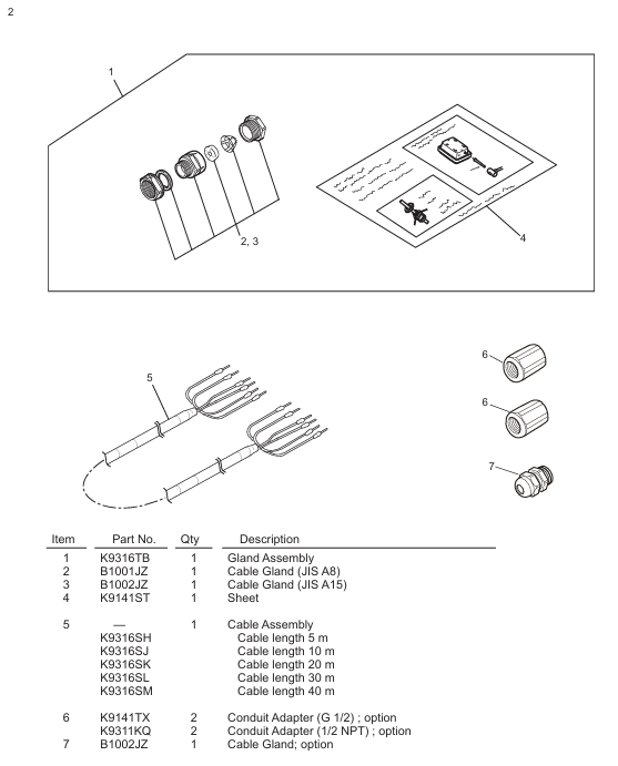
Cable entrance sensor cable: diameter 13mm, equipped with JIS A8 grade cable sealing sleeve (suitable for cable outer diameter 5.5-7mm); Special extension cable: diameter 21mm, equipped with JIS A15 grade cable sealing sleeve (suitable for cable outer diameter 9-12mm)
The length of the dedicated extension cable can be selected from 5m, 10m, 20m, 30m, and 40m, and the end has been pre treated; When installing/AWTB (G1/2 internal thread) or/ANSI (1/2 NPT) conduit adapters, a sealing sleeve and adapter will be included
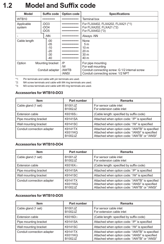
2. Model and suffix code rules
Model structure: WTB10- [Applicable system code] - [Fixed suffix] - [Cable length code]+[Option code], the meanings of each part are as follows:
Meaning of Component Code Examples
Applicable System - DO3 compatible with FLXA402, FLXA202, FLXA21 (pin terminal, cable with pin terminal)
-DO4 compatible with FLXA202, FLXA21 (M4 threaded terminal, with M4 ring terminal cable)
-DO5 compatible with FLXA402 (M3 threaded terminal, with M3 ring terminal cable)
Fixed suffix - NN is used for all models
Cable length -00 without extension cable
-05/-10/-20/-30/-40 Extension cable length 5m/10m/20m/30m/40m
Option code/P includes pipeline installation bracket
/W includes wall installation bracket
/AWTB includes G1/2 internal thread conduit adapter
/ANSI includes 1/2 NPT conduit adapter
Accessories List: Different models of terminal boxes come with different standard accessories. Taking WTB10-DO3 as an example, the standard accessories include sensor cable sealing sleeve (B1001JZ), extension cable sealing sleeve (B1002JZ), and corresponding length extension cable (K9316S □ series). Corresponding brackets are included when installing/P or/W, and conduit adapters are included when installing/AWTB or/ANSI.
Installation process and requirements
1. Preparation before installation
Installation environment:
Outdoor rainproof, sensors should be installed as close as possible to the terminal box;
Avoid high humidity and corrosive gas environments (to prevent contact failures caused by cable breakage, poor insulation, or corrosion);
The terminal box cover is equipped with a silicone desiccant (about 30g), and its moisture absorption status needs to be checked regularly.
Installation tools and accessories: Prepare M5 screws (bracket installation, length=bracket thickness+5mm), M8 screws (wall installation, 3 pieces), U-bolts (pipeline installation, suitable for pipes with an outer diameter of 60.5mm), as well as standard accessories such as cable glands and extension cables according to the installation method.
2. Detailed explanation of installation method
(1) Bracket installation
Drill holes on the bracket according to the installation hole size of the terminal box (4 holes with a diameter of 5.5mm, hole spacing of 75 ± 0.2mm × 70 ± 0.2mm);
Fix the terminal box on the bracket with 4 M5 screws, and the screw depth should cover the thickness of the bracket before penetrating 5mm to ensure firmness.
(2) Pipeline installation (requires/P option support)
Fix the pipeline installation bracket (K9141SA) onto a sturdy pipeline with an outer diameter of 60.5mm (nominal 50A) using U-bolts, washers, and nuts;
Fix the terminal box on the bracket with 4 M5 screws, which can be installed vertically or horizontally.
(3) Wall installation (requires/W option bracket)
Drill holes on the wall according to the size (3 M8 screw holes, with a hole spacing that meets the positioning requirements of the terminal box center);
Fix the wall mounting bracket (K9141SC) to the wall with 3 M8 screws, and then secure the terminal box to the bracket with 4 M5 screws.
3. Cable entrance opening
The cable entrance at the bottom of the terminal box is a pre designed groove (not opened), which needs to be opened with a tool before wiring: align the tip of a cross screwdriver or other tool with the center of the groove, lightly tap the tool head with a hammer, and break the entrance hole along the groove (the sensor cable entrance and the extension cable entrance need to be opened separately).

Wiring operation specifications
1. Sensor cable connection
Dismantling the terminal box cover: Loosen the 2 screws on the front panel and remove the cover;
Installation of cable sealing sleeve: Remove the nut of JIS A8 grade cable sealing sleeve (B1001JZ) and assemble it to the sensor cable inlet in the order of "nut → gasket → main body → cap", ensuring that the sealing sleeve is in contact with the box body;
Cable insertion: Remove the cap, clamping claw, and rubber gasket from the sealing sleeve, place it on the sensor cable, and insert the front end of the cable into the terminal box;
Wiring: Connect the sensor cable core wires according to the terminal numbers (refer to the correspondence between "core wire color terminal number": brown -16, white -12, black -11, green -14, yellow -15, red -13), ensuring correct and secure wiring;
Sealing fixation: Install the rubber gasket and clamping claw back into the sealing sleeve, tighten the cap to prevent water ingress, and be careful not to overtighten and damage the cable.
2. Extend cable connection (terminal box converter)
Preparation work: The two ends of the extension cable have been pre treated (with no directional difference). If conduit protection is required, the DIN Pg13.5 sealing sleeve at the inlet of the converter sensor cable needs to be replaced with a JIS A15 level sealing sleeve (standard);
Install sealing sleeve/adapter:
No conduit: Install the JIS A15 grade sealing sleeve (B1002JZ) onto the extension cable in the order of "cap → clamping claw → rubber gasket → main body → gasket → nut", and fix the nut after the cable enters the terminal box;
With conduit: Replace the cap of the sealing sleeve with the optional/AWTB (G1/2) or/ANSI (1/2 NPT) adapter, tighten the adapter, and connect the conduit union;
Wiring: Connect the extension cable core wires according to the terminal numbers to ensure consistency with the terminal correspondence of the sensor cable;
Cover the box: After checking the wiring is correct, install the front panel cover back into the terminal box and tighten the screws to ensure sealing.
3. Wiring diagram
WTB10-DO3/- DO4 terminal box: The sensor cable and extension cable are connected to terminals 11 (T1, black), 12 (T2, white), 13 (IE, red), 14 (S, green), 15 (RE, yellow), 16 (SE, brown). The converter (FLXA402/FLXA202/FLXA21) receives signals through the extension cable;
WTB10-DO5 terminal box: only compatible with FLXA402 converter, wiring logic is consistent with - DO3/- DO4, please note that the terminal thread specification is M3 (- DO3 is pin type, - DO4 is M4).

Inspection and maintenance
1. Regular inspection (recommended once a year or every two years, with early inspection in case of abnormalities)
**Moisture inspection * *: Remove the terminal box cover and check if the interior is damp. If it is damp, use a hair dryer to dry it; Several desiccants (silica gel) are saturated with moisture, replace with spare desiccants (30g/part, part number K9020XR);
Corrosion inspection: Check whether the terminals and wires have corroded due to the invasion of corrosive gases. If there is a risk of poor contact or wire breakage, the corroded parts need to be replaced; When replacing the core wire crimping terminal, it is necessary to keep the wiring number label (ribbon) to avoid wiring errors.
2. Maintain parts list
The commonly used maintenance parts for terminal boxes include seals, fasteners, desiccants, etc. Different models correspond to slightly different part numbers. Taking WTB10-DO3 as an example:
Part name, part number, quantity, and purpose
O-ring G9303NB 2 sealing box gap
Desiccant (30g) K9020XR 1 absorbs moisture inside the box
Panel screws (M3 × 4) Y9304LB 2 fix the front panel
Install screws (M5 × 8) Y9508JU 4 to fix the terminal box and bracket
Cable sealing sleeve (JIS A8) B1001JZ 1 sensor cable sealing
Cable sealing sleeve (JIS A15) B1002JZ 1 extension cable sealing
Key precautions
Installation sealing: All cable entrances and box covers must be sealed to prevent rainwater and moisture from entering; When adapting the conduit, the flexible joint should be tightened to avoid cable protection failure;
Wiring specifications: strictly follow the corresponding wiring of "core wire color terminal number", incorrect wiring may cause measurement abnormalities or equipment damage; The length of the extended cable must be consistent with the selection and cannot be cut or spliced arbitrarily;
Environmental protection: Although it is an outdoor type, it is still necessary to avoid long-term exposure to strong corrosion and high humidity environments, and regularly check the condition of desiccants and seals;
Parts replacement: Only spare parts certified by Yokogawa (such as sealing sleeves, brackets, desiccants) can be used. Non certified parts may affect equipment performance and safety.
- OMRON
- ABB
- General Electric
- EMERSON
- Honeywell
- HIMA
- ALSTOM
- Rolls-Royce
- MOTOROLA
- Rockwell
- Siemens
- Woodward
- YOKOGAWA
- FOXBORO
- KOLLMORGEN
- MOOG
- KB
- YAMAHA
- BENDER
- TEKTRONIX
- Westinghouse
- AMAT
- AB
- XYCOM
- Yaskawa
- B&R
- Schneider
- KONGSBERG
- NI
- WATLOW
- ProSoft
- SEW
- ADVANCED
- Reliance
- TRICONEX
- METSO
- MAN
- Advantest
- STUDER
- DANAHER MOTION
- Bently
- Galil
- EATON
- MOLEX
- DEIF
- B&W
- ZYGO
- Aerotech
- DANFOSS
- Beijer
- Moxa
- Rexroth
- Johnson
- WAGO
- TOSHIBA
- BMCM
- SMC
- HITACHI
- HIRSCHMANN
- Application field
- XP POWER
- CTI
- TRICON
- STOBER
- Thinklogical
- Horner Automation
- Meggitt
- Fanuc
- Baldor
- SHINKAWA
- Other Brands
- UniOP
- KUKA
- Iba
- Beckhoff
- ADLINK
-
 Basler Electric BE1-700 Digital Protective Relay
 -
 Basler Electric SR8A-2B01B3A Static Voltage Regulator
 -
 Basler Electric SR4A-2B01B3E Static Voltage Regulator
 -
 Basler Electric 9017709102 PC Board
 -
Basler Electric SR4A-2B01B3A Static Voltage Regulator
-
 Basler Electric PRS-250 Veri-Sync Relay
 -
 Basler Electric 9066800102 Excitation Support System
 -
 Basler Electric BE1-87G Generator Differential Relay 9 1708 18 100
 -
 Basler Electric 36T865-2 BE03752001 Power Supply
 -
 Basler Electric M-300 149D940G02 Power Supply
 -
 Basler Electric ACA2040-25GM 4Mp 25Fps Area Scan Camera
 -
 Basler BE1-87G-S1A-A1C-A0N0 Differential Relay
 -
 Basler SR8A-2B06B3E Static Regulator SR8A2B06B3E
 -
 Basler SCP-210 Frequency Controller 9095400100
 -
 Basler BE1-59-A3E-A1J-N1N3F Overvoltage Relay BE159A3EA1JN1N3F
 -
 Basler 9 2011 11 100 Bracket Mounted Terminal Unit
 -
Basler 9 1606 00 101 Voltage Regulator
-
 Basler CBS-377 Current Boost System 9109600102
 -
 Basler 8650C72 Exciter Control Module PCB Rev 5
 -
 Basler C2EE1PA0N1F BE1-32R Reverse Power Relay
 -
 ADLINK HPCI-14S12U - Industrial Control Backplane 12PCI Backplane PCI-14S Passive Backplane
 -
-0010.png) ADLINK PCIe-GIE74C - image acquisition card 4-CH GigE Vision PoE+ Frame Grabber
ADLINK PCIe-GIE74C - image acquisition card 4-CH GigE Vision PoE+ Frame Grabber -
-0010_1.png) ADLINK PCI-8164 - control card 4-Axis Advanced Motion Controller Board
ADLINK PCI-8164 - control card 4-Axis Advanced Motion Controller Board -
 ADLINK PCIe-U304 - 4 Port USB3 PCIe Frame Grabbers USB Screw Hole Card
 -
 ADLINK PCI-9112 - Multi-Function Data Acquisition Card DAQ Card
 -
 ADLINK PCI-7432 - 51-12013-0A50 4-CH Isolated Numérique I/O PCI Cartes Digital I/O Card
 -
 ADLINK PCA-6106P3-0C1 REV.C1 - backplane 6-Slot Passive Backplane Board
 -
 ADLINK PCI-7224 - 24-CH Opto-Isolated Digital I/O PCI Board
 -
 ADLINK CPCI-7433R(G) - Digital Input Board Rear I/O CompactPCI Card
 -
 ADLINK EBP-13E4 - 51-46703-0A30 Industrial PC Backplane Passive Backplane
 -
 ADLINK PCIE-HDV62 - Image acquisition card High Definition Video Frame Grabber
 -
 ADLINK EBP-13E4 - 51-46703-0A30 Industrial Backplane Board Passive Backplane
 -
 ADLINK 90111-B1 / CPCI-6770 - PCB CPU MODULE CompactPCI Single Board Computer
 -
 ADLINK PCI-7248 - DATA ACQUISITION PCI CARD 48-CH Parallel Digital I/O Board
 -
 ADLINK PCI-7230 - 51-12003-0a50 board PCI7230 32-CH Isolated Digital I/O Card
 -
 ADLINK PCI2A000CB - 51-20000-0B30 Multi-Function DAQ Card Baseboard
 -
 ADLINK PCI-8134-005 - 4-Axis Motion Controller Card
 -
 ADLINK PCI-7224 - 24-CH Opto-Isolated Digital I/O PCI Card
 -
 ADLINK PCI-7434 - 64-CH Isolated Digital Output Card
 -
 ADLINK PCI-8132 - motion control card 2-Axis Servo & Stepper Controller
 -
 ADLINK PCI-8134 - Motion Controller PCI Card 4-Axis Controller Board
 -
 ADLINK PCI-8164 - Motion Control Card 51-12406-0A40 4-Axis Controller
 -
 ADLINK 51-12001-0C20 - Circuit Board Data Acquisition Interface Module Hardware
 -
 ADLINK NuPR0-840 - industrial control motherboard Full-Size PICMG CPU Board
 -
 ADLINK PCI-7444 - 51-12023-0A10 card 128-CH Isolated Digital Output Board
 -
 ADLINK PCI-1612B - data acquisition card 4-Port RS-232/422/485 Serial Communication Card
 -
 ADLINK PCI-6208V 009 - 8/16-CH 16-Bit Analog Output Cards PCB-I-E-482=6BX3
 -
 ADLINK NUPRO-935A/LV - industrial control motherboard Full-Size PICMG SBC Board
 -
 ADLINK PCI-9114DG - Multi-Function DAQ Card Data Acquisition PCI Card
 -
 ADLINK ACL-7130 - Data acquisition card Isolated Digital I/O Board
 -
 ADLINK ABX-6300D-4E1-BP - board ABX6300D4E1BP Video Interface Expansion Card
 -
 ADLINK CPCI-6940 - CPCI-6940/D1539/M16-0(EA)-000E 6U CompactPCI Processor Board
 -
 ADLINK NuPRO-760 - industrial control motherboard Half-Size PICMG SBC CPU Board
 -
 ADLINK IMB-M42H (G)-0020 - industrial control motherboard LGA1155 Micro-ATX Mainboard
 -
 ADLINK RTV-24 / PCI-MP4S - 51-12519-1C30 4-Channel Real Time Video Capture Board
 -
 ADLINK PCI-8134 - 4-Axis Servo & Stepper Motion Controller Card
 -
 ADLINK MXC-6101D - V.PC000.002.ST.00 Box PC Configurable Embedded Computer
 -
.png) ADLINK PCI-8134A - 51-12421-0A10 Motion Control Card 4-Axis Controller Card
ADLINK PCI-8134A - 51-12421-0A10 Motion Control Card 4-Axis Controller Card -
 ADLINK DIN-100S / DIN-100SA1 - Technology SCSI-II TB 100-PIN Terminal Block Board
 -
.png) ADLINK DIN-812M001 / DIN812M001 - 51-14034-0A1 51140340A1 Terminal Module Breakout Interface
ADLINK DIN-812M001 / DIN812M001 - 51-14034-0A1 51140340A1 Terminal Module Breakout Interface -
_1.png) ADLINK PCI-8164 - Servo motion control 4-Axis Advanced Controller Card
ADLINK PCI-8164 - Servo motion control 4-Axis Advanced Controller Card -
 ADLINK PCIe-GIE64 - Acquisition card GigE Vision PoE+ Frame Grabber
 -
 ADLINK M-302 - Industrial control motherboard ATX PC Board Mainboard
 -
 ADLINK PCI-8134 - Motion Controller PCI Card 4-Axis Controller Board
 -
 ADLINK PCI-RTV24 - Image capture card Analog Video Frame Grabber
 -
 ADLINK PCI-8102 - Motion control card 2-Axis Servo & Stepper Controller Board
 -
 ADLINK PCI-9112 REV.B1 - Card Multi-Function Data Acquisition Card
 -
 ADLINK HSI-DI32-M-N / HSL-TB32-M-DIN - Discrete I/O MODULE Distributed Automation Module System
 -
 ADLINK PCI-7296 - IO card REV.A3 96-CH Parallel Digital I/O Card
 -
-0020.png) ADLINK DIN-814P-A4 / 814Y - terminal board Motion Control Interface Block
ADLINK DIN-814P-A4 / 814Y - terminal board Motion Control Interface Block -
 ADLINK DIN-814P-A4 - 51-14056-0A10 PCB-I-E-2736=ZA01 Screw Terminal Board Breakout
 -
 ADLINK M-322 - motherboard Industrial Control Computer Mainboard
 -
 ADLINK NUPRO-406 REV:B1 - industrial control motherboard Full-Size PICMG CPU Board
 -
 ADLINK AMP-204C - card DSP-Based 4-Axis Advanced Pulse-Train Controller
 -
 ADLINK HPCI14S REV.B1 - industrial computer baseboard 14-Slot Passive Backplane
 -
 ADLINK PCI-7250 - 8-CH Relay Output & 8-CH Isolated DI PCI Card
 -
 ADLINK EBP-13E2 - baseplate Passive Backplane Industrial Computer Chassis Board
 -
 ADLINK LPCI-3488A - PCI-GPIB card 51-12801-0A30 acquisition card IEEE-488 Interface Board
 -
 ADLINK PCI-6216V-GL - 51-12201-0C30 16-CH 16-Bit Voltage Analog Output Card
 -
 ADLINK ACL-8454 - 16-CH Isolated Digital I/O & 4-CH Counter Card
 -
 ADLINK HPCI-9S7U - backplane Passive Backplane Compatible with NuPRO-A301 852 841 842
 -
 ADLINK DAQ-2010-007 - Simultaneous-Sampling Multi-Function Data Acquisition Card
 -
 ADLINK MP-C154 - 51-64205-0A10 Motion Control Card 4-Axis Controller Board
 -
 ADLINK MXE-202/mSSD16B/WiFi-BT - Matrix Rugged I/O Platform Embedded Fanless Computer
 -
 ADLINK CM-920-R-17 - PC/104-Plus Single Board Computer Module Intel Celeron M
 -
 ADLINK PCI-7250 NSMP - 8-CH Relay Output & 8-CH Isolated DI Card
 -
 ADLINK PCI-8164 - 4-Axis Motion Controller PCI Card W/ Cable and Breakout Box
 -
 ADLINK EMX-100 - Ethernet-based 4-axis Motion Controllers Distributed Motion Module
 -
.png) ADLINK PCI-8134A - Press control card 4-Axis Motion Controller Board
ADLINK PCI-8134A - Press control card 4-Axis Motion Controller Board -
 ADLINK M-845EG REV:3.2 - industrial motherboard Pentium 4 Socket 478 Micro-ATX
 -
 ADLINK PCI-9114A Rev A2 DG - card High-Resolution Multi-Function Data Acquisition Board
 -
 ADLINK IEC-915GV - REV 1.1 Industrial motherboard Socket 478 CPU Board
 -
 ADLINK PCI-9111DG(G) - Data Acquisition Card Multi-Function DAQ Card
 -
 ADLINK HPCI-15S10 REV:B2 - Industrial computer base plate Passive Backplane Board
 -
 ADLINK NuPR0-840 / NuPR0-840DV - industrial control motherboard Full-size PICMG CPU Board
 -
 ADLINK RTV-24 / PCI-MP4S - 51-12519-1C30 4-Channel Real Time Video Capture Board
 -
 ADLINK NUPRO-780 - industrial control motherboard Pentium III Single Board Computer
 -
 ADLINK PCI-7296 - 0050 card 96-CH Opto-Isolated Parallel DIO Card Set
 -
-0040.png) ADLINK NUPRO-780 - industrial control motherboard PICMG Full-Size SBC
ADLINK NUPRO-780 - industrial control motherboard PICMG Full-Size SBC -
 ADLINK PCI-7248 - 51-12006-0A3 002 Pci 7248 48-CH Parallel Digital I/O Card
 -
 ADLINK PCI-7230 - 32-CH Isolated Digital I/O Card
 -
 ADLINK AMP-204C - motion control card 4-Axis Advanced Controller Board
 -
.png) ADLINK PCI-1714UL - Card Ultra High-Speed 4-CH Simultaneous Sampling DAQ
ADLINK PCI-1714UL - Card Ultra High-Speed 4-CH Simultaneous Sampling DAQ -
 ADLINK NuPRO-E330 - industrial computer equipment motherboard PICMG 1.3 SHB SBC
 -
 ADLINK AMP-204C - DSP-Based 4-Axis Advanced Pulse-Train Motion Controller Module
 -
 ADLINK PCI-7256 - 001 51-12206-0A2 REV.A2 LPCI-7256 16-CH Latching Relay Output Card
 -
 ADLINK ND6050 - NUDAM DIGITAL I/0 MODULE Distributed I/O Unit
 -
 ASEM BM100 - Box PC Embedded Fanless Industrial Computer
 -
-3650.png) ADLINK PCI-7250 - PCI Acquisition Card 8-CH Relay Output & Isolated DI Board
ADLINK PCI-7250 - PCI Acquisition Card 8-CH Relay Output & Isolated DI Board -
 ADLINK PCI-8164 - Servo motion control 4-Axis Controller Card
 -
 ADLINK NuPRO-A40H - Industrial Motherboard 51-41807-1A30 OSP LGA1155 H61
 -
 ADLINK ADMAX X300 SERVER - 51066010-0A30 motherboard Multi-Processor Mainboard
 -
 ADLINK CMe-GIE62+ - 51-32903-0A30 control card PC/104-Plus GigE Vision Frame Grabber
 -
 ADLINK NUPRO-780 - industrial control motherboard Full-Size PICMG SBC CPU Board
 -
 ADLINK ETX-AT-N270-18/GKTEL - 51-71111-OB10 motherboard ETX CPU Module Board
 -
 ADLINK DIN-812M - interface module Terminal Block Connection Board
 -
 ADLINK IMB-M42H - industrial control motherboard LGA1155 Micro-ATX Mainboard
 -
ADLINK PXIS-2508 - 8-slot 3U PXI Instrument Chassis Power Hardware Assembly
-
ADLINK AMP-208C - Motion Control card DSP-Based 8-Axis Pulse-Train Controller
-
ADLINK PCI-9111 / PCI-9111DG - Multi-Function Data Acquisition Card DAQ Board
-
ADLINK IEEE-488 GPIB card - Bus Interface Controller Communication Board
-
ADLINK RTV-24 - 51-12519-1C30 image acquisition card Video Frame Grabber Card
-
ADLINK TB-24P/24-01 - Board 24 Way Screw Terminal Breakout Board
-
ADLINK HSL-DI16DO16-DB-NN - 51-23015-0A40 Distributed Discrete I/O Module Set
-
ADLINK PCI-7442 - switch quantity card data acquisition card 64-CH Isolated Card
-
ADLINK ACL-7130 REV. B2 - industrial control capture card Isolated Digital I/O PCI Card
-
ADLINK PCI-6S / PCI6S - Backplane 6-Slot Passive Backplane Chassis Board
-
ADLINK ACL-8113A - card Isolated Digital Input Card


