
Woodward easyYgen LS-6XT Circuit Breaker Control Unit: Technical Characteristics, Installation and Application Guide
Woodward easyYgen LS-6XT Circuit Breaker Control Unit: Technical Characteristics, Installation and Application Guide
Introduction
In the field of modern generator system management and power distribution, intelligent circuit breaker control units play a crucial role. The easyYgen LS-6XT series launched by Woodward is a high-performance control unit designed to meet this demand. As an industrial grade product designed in Germany, LS-6XT not only has excellent reliability, but also provides flexible configuration options and wide application compatibility. This article will delve into the technical characteristics, installation requirements, configuration methods, and practical application scenarios of the device, providing a comprehensive reference guide for engineers and technicians.
Product Overview and Technical Features
1.1 Product positioning and functions
The Woodward easyYgen LS-6XT series is a circuit breaker control unit designed specifically for engine generator system management. This device can be used as an independent unit or combined with Woodward easyYgen-3400/3500XT generator control unit and/or easyYgen | GC-3400XT to form a complete power management system.
The core functions of LS-6XT include:
Dual circuit breaker control (CBA and CBB modes)
System synchronization check and grid connection function
Real time monitoring of power parameters (voltage, current, frequency, power, power factor)
Advanced protection functions (overvoltage, undervoltage, overclocking, underflocking, etc.)
Multiple communication interface support (CAN, Ethernet, RS-485, USB)
Programmable Logic Manager ™) Analog Manager ™)
1.2 Technical Specifications Highlights
According to Chapter 8 "Technical Specifications" of the technical manual, LS-6XT has the following key characteristics:
Measurement performance:
Voltage measurement range: 0-690V AC (phase voltage)
Current measurement range: compatible with 1A/5A CT
Frequency measurement range: 0-75Hz
Power measurement accuracy: ± 0.5% of rated value
Real time clock battery: lithium battery backup
Environmental adaptability:
Working temperature: -25 ° C to+70 ° C
Storage temperature: -40 ° C to+85 ° C
Protection level: Complies with UL standards and is suitable for Type 1 enclosures
Humidity range: 5% to 95% relative humidity (non condensing)
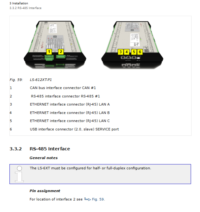
Interface capability:
3 Ethernet ports (10/100Base-T)
CAN bus interface (supporting CANopen protocol)
RS-485 serial interface
USB 2.0 service port
12 digital inputs/12 relay outputs
3 analog inputs/2 analog outputs
1.3 Hardware Configuration and Packaging Content
The standard delivery scope includes:
EasyYgen LS-6XT equipment body
All pluggable terminal connectors
Installation Program Supplemental Instructions (IPS) and Printed QR Code Labels (2 copies)
Configuration files and technical manuals stored in the internal memory of the device
It is worth noting that the documents stored inside the device are in "delivery status" and may not be the latest version. The latest version needs to be obtained from Woodward's official website.
Safety regulations and installation requirements
2.1 Safety precautions
Section 1.3 of the technical manual emphasizes the important safety regulations that must be followed when using LS-6XT:
Personnel qualification requirements:
Electrical work must be carried out by qualified electricians
Operators need to receive relevant training and be familiar with all applicable regulations
Prohibit personnel under the influence of alcohol and drugs from operating equipment
Electrical safety measures:
Ensure that the system is powered off and prevent accidental restarts before operation
Voltage measurement input requires 2-6A slow melting fuse
One end of the CT secondary side must be grounded nearby
The power line requires the use of cables with a temperature rating of not less than 90 ° C
Anti static protection:
Release static electricity by touching grounded metal objects before operation
Suggest using an ESD wristband
Avoid wearing synthetic fiber clothing
Keep plastic and vinyl materials away from the work area
2.2 Mechanical Installation
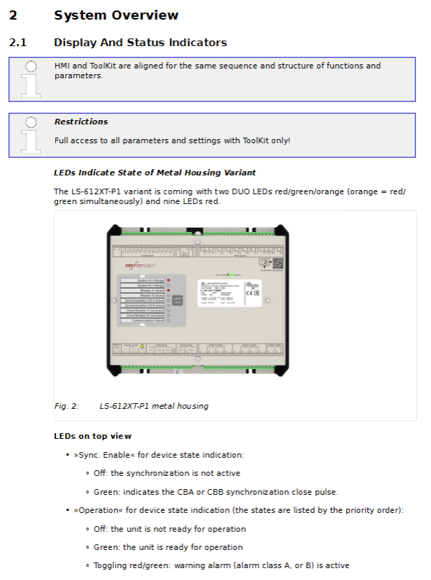
For the sheet metal shell model (LS-612XT-P1), installation should follow the following steps:
Hole positioning: Drill installation holes according to the hole spacing of 42.45 × 96.2mm
Equipment fixation: Use screws with a maximum diameter of 6mm (M6) for fixation
Torque control: Tighten according to the required torque of the screw quality grade
Wiring space: Ensure sufficient operating space above and below the terminals
Key installation dimensions:
Equipment width: 250mm
Installation hole spacing: horizontal 42.45mm, vertical 96.2mm
Maximum wire diameter: The terminal supports a maximum of 2.5mm ² wire
2.3 Electrical Connections
Power connection:
Power range: 8-40V DC (nominal 12/24V)
Positive terminal connected to terminal 63, negative terminal connected to terminal 64
Protective grounding (PE) connected to the bottom center of the sheet metal shell
Suggest using 6A fuses or C-type miniature circuit breakers for protection
Voltage measurement connection:
System A voltage: terminals 30-36
System B voltage: terminals 22-28
Auxiliary voltage: terminals 38-40
Supports multiple wiring configurations: 3-phase 4-wire, 3-phase 3-wire, 1-phase 3-wire, 1-phase 2-wire
Current measurement connection:
System A current: terminals 3-8 (L1, L2, L3 phases)
System B current: terminals 1-2 (single-phase)
The CT direction should be based on the software version. Note that version 2.10-0 points to system A, while version 2.10-1 and above points to system B
Power measurement configuration:
CBA mode: measuring power flow between system A and system B
CBA/BBB mode: Simultaneously monitor the power status of two circuit breakers
The definition of power factor follows international standards (inductive load is positive, capacitive load is negative)
System configuration and parameter settings
3.1 Access Level and Password System
LS-6XT adopts a multi-level password protection system, providing 5 access levels:
Basic level (CL01): Restricted viewing permission, no configuration permission
Temporary debugging level (AC02): Algorithm code access, expires after session ends
Debugging Level (CL03): General Debugging Parameter Access
Temporary Super Debugging Level (AC04): Algorithm Code Access Advanced Features
Super Debugging Level (CL05): Almost Full Access (except for calibration and super user items)
Access channels include:
Local HMI of the device (basic code input)
USB connection ToolKit (user account login)
Ethernet remote panel (user account login)
Third party devices use Modbus TCP/CANopen/RS-485
3.2 HMI Operation and Navigation
The main screen of the device is divided into five main areas:
Numerical display area: real-time data such as voltage, current, frequency, power, etc
Status message area: operating mode, device status
Alarm message area: Latest unconfirmed alarm
Single line diagram area: visualization of circuit breaker status and power flow direction
Soft key function area: Navigation and operation control
Special function screen:
Customer customized screen: up to 18 customizable monitoring values can be configured
Synchronous oscilloscope: visually display the phase difference between system A and B
Logic Manager: Visualize Logic Conditions and Variable States
Event history: system event records with timestamps
3.3 Key parameter configuration
Language and clock settings:
Supports English, German, and one reserved language
Real time clock with configurable time zone and daylight saving time rules
Network time can be synchronized through SNTP protocol
Measurement configuration:
Voltage Transformer Ratio Setting (Parameters 1800, 1803, 1812)
Current Transformer Ratio and Direction Configuration
Definition of power measurement symbols (based on CT installation direction)
Circuit breaker configuration:
Operation mode selection: manual/automatic
Synchronization parameters: frequency difference, voltage difference, phase angle, dwell time
Dead bus closure condition setting
Logical Command Configuration (AMF Function)
Monitoring function configuration:
System A/B protection: overvoltage, undervoltage, overclocking, underfrequency, voltage asymmetry, etc
Circuit breaker monitoring: closing transition monitoring, unloading mismatch detection
Communication monitoring: CAN, Ethernet, multi unit system status
Application Mode and Advanced Features
4.1 Application layer architecture
LS-6XT supports a two-tier application architecture:
Layer 1: Generator Unit Layer
Communicate with easyYgen-3000XT and other LS-6XT
Support CBA or CBA/BBB circuit breaker modes
Special application modes: L-MCB, L-GGB, L-MCB/GGB
Main power failure detection and main power decoupling
Layer 3: Power Station Layer
Communicate with group controller (GC) and other LS-6XT
Support CBA or CBA/BBB circuit breaker modes
Main power fault detection and decoupling (GCB)
4.2 Synchronization check function
As a redundancy check function, synchronous inspection enhances system security:
Available command variables:
02.29 Synchronization conditions: dependent on voltage, frequency, and phase angle
02.30 Dead bus closure condition: depends on system A/B voltage and dead bus configuration
02.28 Synchronization check relay: Triggered when any of the above conditions are met
Key parameters:
Positive/Negative Frequency Difference CBA (5711/5712)
Voltage difference CBA (5710)
Maximum positive/negative phase angle CBA (5713/5714)
Phase matching dwell time CBA (5717)
4.3 Expansion of External I/O Modules
External I/O modules can be connected via CAN1 bus:
IKD1: Up to 2, providing 16DI/16DO
IKD-IN-16:1, providing 16DI
IKD-OUT-16:1, providing 16DO
The configuration tool can be accessed through ToolKit and supports flexible digital input monitoring and relay output control.
4.4 Communication and Protocol Support
CAN interface:
CAN1 interface supports CANopen protocol
Support Process Data Objects (PDO) and Service Data Objects (SDO)
Configurable load balancing communication parameters
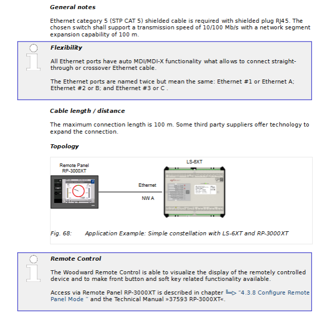
Ethernet interface:
Three independent 10/100Base-T ports
Supports Modbus TCP/IP protocol
Remote Panel Access (RP-3000XT)
System interconnection function (new feature)
Serial interface:
RS-485 supports half duplex/full duplex operation
Modbus RTU protocol
USB 2.0 Device Interface (ToolKit Connection)
Load balancing:
Broadcast messages via CAN bus or UDP (Ethernet)
Configurable transmission rate and timeout period
Support redundant communication paths
Maintenance and troubleshooting
5.1 Daily Maintenance
Indicator light test:
Through the HMI "LAMPTEST" button or logical command variable 04.04
Test all panel LED indicator lights
System restart:
Both ToolKit and HMI provide restart function
Wait up to 20 seconds after parameter changes to ensure saving
Event and alarm management:
The alarm is divided into 6 levels (A-F)
Event history with timestamp
Alarm can be confirmed locally or remotely
5.2 Common problem handling
Communication fault inspection:
Verify that all devices have consistent baud rates
Check the terminal resistance of the CAN bus (120 Ω at both ends)
Confirm that the bus length does not exceed the speed limit
Check if the cable is close to the power cord
Measurement abnormality troubleshooting:
Confirm that the CT/PT ratio setting is correct
Check the wiring phase sequence
Verify voltage/current measurement range configuration
Check if the grounding connection is good
Circuit breaker operation issues:
Confirm operating mode (manual/automatic)
Check the status of the enable signal
Verify if the synchronization conditions are met
Check the configuration of the logic manager
5.3 Software Update
Get the latest files:
Accessing the complete product documentation through QR code
Download the latest configuration file from Woodward's official website
Use ToolKit 7.0.1 or higher version
Update precautions:
Hardware compatibility check (some hardware is incompatible with older software versions)
Backup the current configuration before updating
Perform updates at the super debug level (CL05)
Practical application case analysis
6.1 Independent Application Mode (A01)
In independent operation mode, LS-6XT can manage a single circuit breaker (CBA mode) or dual circuit breakers (CBA/BBB mode). Typical applications include:
Basic main power source - generator set switching:
System A serves as the main power source, while System B serves as the generator set
Automatically switch to the generator set when the main power supply fails
Automatically synchronize and switch back to the main power supply after the main power supply is restored
Key configuration parameters:
Main power decoupling threshold setting
Generator start-up delay
Synchronization check parameter optimization
6.2 Integrated application with easyYgen (A03/A04)
When LS-6XT is used in conjunction with easyYgen-3400XT/3500XT, a complete generator control system can be formed:
Parallel operation of multiple generator sets:
An externally operated main circuit breaker (MCB)
Multiple generator sets are connected in parallel through generator busbar circuit breakers (GGBs)
Load balancing and frequency/voltage modulation control
H configuration system:
Two incoming main power supplies with connecting circuit breakers
Multiple generator sets support
Complex logic interlocking and priority management
6.3 Special Application Configuration
Digital input monitoring (CBA response):
Can be configured as normally open or normally closed
Response signal timeout detection
Circuit breaker fault alarm
Ethernet interconnection function:
Multi device data synchronization
Remote configuration and monitoring
System redundancy and fault switching
Technological Development Trends and Suggestions
7.1 Software Function Enhancement
According to the revision history, LS-6XT continues to add new features:
Ethernet interconnection function (version 2.14-0)
External reactive power measurement
Modbus master station function
Logical command support (AMF function)
System rationality monitoring
7.2 Hardware compatibility considerations
Important precautions:
Software versions above 2.13-0 require hardware adjustments
Old hardware may not be compatible with new software
Before upgrading, it is necessary to check the hardware version
7.3 Best Practice Recommendations
Installation phase:
Carefully plan the wiring to avoid interference
Ensure proper cable shielding and grounding
Reserve sufficient maintenance space
Configuration phase:
Starting from default settings, gradually adjust
Record all parameter changes
Conduct comprehensive testing before putting it into operation
Operation phase:
Regularly check event logs
Monitor communication status
Keep software and documentation updated
- OMRON
- ABB
- General Electric
- EMERSON
- Honeywell
- HIMA
- ALSTOM
- Rolls-Royce
- MOTOROLA
- Rockwell
- Siemens
- Woodward
- YOKOGAWA
- FOXBORO
- KOLLMORGEN
- MOOG
- KB
- YAMAHA
- BENDER
- TEKTRONIX
- Westinghouse
- AMAT
- AB
- XYCOM
- Yaskawa
- B&R
- Schneider
- KONGSBERG
- NI
- WATLOW
- ProSoft
- SEW
- ADVANCED
- Reliance
- TRICONEX
- METSO
- MAN
- Advantest
- STUDER
- DANAHER MOTION
- Bently
- Galil
- EATON
- MOLEX
- DEIF
- B&W
- ZYGO
- Aerotech
- DANFOSS
- Beijer
- Moxa
- Rexroth
- Johnson
- WAGO
- TOSHIBA
- BMCM
- SMC
- HITACHI
- HIRSCHMANN
- Application field
- XP POWER
- CTI
- TRICON
- STOBER
- Thinklogical
- Horner Automation
- Meggitt
- Fanuc
- Baldor
- SHINKAWA
- Other Brands
- UniOP
- KUKA
- Iba
- Beckhoff
- ADLINK
-
 Basler Electric BE1-700 Digital Protective Relay
 -
 Basler Electric SR8A-2B01B3A Static Voltage Regulator
 -
 Basler Electric SR4A-2B01B3E Static Voltage Regulator
 -
 Basler Electric 9017709102 PC Board
 -
Basler Electric SR4A-2B01B3A Static Voltage Regulator
-
 Basler Electric PRS-250 Veri-Sync Relay
 -
 Basler Electric 9066800102 Excitation Support System
 -
 Basler Electric BE1-87G Generator Differential Relay 9 1708 18 100
 -
 Basler Electric 36T865-2 BE03752001 Power Supply
 -
 Basler Electric M-300 149D940G02 Power Supply
 -
 Basler Electric ACA2040-25GM 4Mp 25Fps Area Scan Camera
 -
 Basler BE1-87G-S1A-A1C-A0N0 Differential Relay
 -
 Basler SR8A-2B06B3E Static Regulator SR8A2B06B3E
 -
 Basler SCP-210 Frequency Controller 9095400100
 -
 Basler BE1-59-A3E-A1J-N1N3F Overvoltage Relay BE159A3EA1JN1N3F
 -
 Basler 9 2011 11 100 Bracket Mounted Terminal Unit
 -
Basler 9 1606 00 101 Voltage Regulator
-
 Basler CBS-377 Current Boost System 9109600102
 -
 Basler 8650C72 Exciter Control Module PCB Rev 5
 -
 Basler C2EE1PA0N1F BE1-32R Reverse Power Relay
 -
 ADLINK HPCI-14S12U - Industrial Control Backplane 12PCI Backplane PCI-14S Passive Backplane
 -
-0010.png) ADLINK PCIe-GIE74C - image acquisition card 4-CH GigE Vision PoE+ Frame Grabber
ADLINK PCIe-GIE74C - image acquisition card 4-CH GigE Vision PoE+ Frame Grabber -
-0010_1.png) ADLINK PCI-8164 - control card 4-Axis Advanced Motion Controller Board
ADLINK PCI-8164 - control card 4-Axis Advanced Motion Controller Board -
 ADLINK PCIe-U304 - 4 Port USB3 PCIe Frame Grabbers USB Screw Hole Card
 -
 ADLINK PCI-9112 - Multi-Function Data Acquisition Card DAQ Card
 -
 ADLINK PCI-7432 - 51-12013-0A50 4-CH Isolated Numérique I/O PCI Cartes Digital I/O Card
 -
 ADLINK PCA-6106P3-0C1 REV.C1 - backplane 6-Slot Passive Backplane Board
 -
 ADLINK PCI-7224 - 24-CH Opto-Isolated Digital I/O PCI Board
 -
 ADLINK CPCI-7433R(G) - Digital Input Board Rear I/O CompactPCI Card
 -
 ADLINK EBP-13E4 - 51-46703-0A30 Industrial PC Backplane Passive Backplane
 -
 ADLINK PCIE-HDV62 - Image acquisition card High Definition Video Frame Grabber
 -
 ADLINK EBP-13E4 - 51-46703-0A30 Industrial Backplane Board Passive Backplane
 -
 ADLINK 90111-B1 / CPCI-6770 - PCB CPU MODULE CompactPCI Single Board Computer
 -
 ADLINK PCI-7248 - DATA ACQUISITION PCI CARD 48-CH Parallel Digital I/O Board
 -
 ADLINK PCI-7230 - 51-12003-0a50 board PCI7230 32-CH Isolated Digital I/O Card
 -
 ADLINK PCI2A000CB - 51-20000-0B30 Multi-Function DAQ Card Baseboard
 -
 ADLINK PCI-8134-005 - 4-Axis Motion Controller Card
 -
 ADLINK PCI-7224 - 24-CH Opto-Isolated Digital I/O PCI Card
 -
 ADLINK PCI-7434 - 64-CH Isolated Digital Output Card
 -
 ADLINK PCI-8132 - motion control card 2-Axis Servo & Stepper Controller
 -
 ADLINK PCI-8134 - Motion Controller PCI Card 4-Axis Controller Board
 -
 ADLINK PCI-8164 - Motion Control Card 51-12406-0A40 4-Axis Controller
 -
 ADLINK 51-12001-0C20 - Circuit Board Data Acquisition Interface Module Hardware
 -
 ADLINK NuPR0-840 - industrial control motherboard Full-Size PICMG CPU Board
 -
 ADLINK PCI-7444 - 51-12023-0A10 card 128-CH Isolated Digital Output Board
 -
 ADLINK PCI-1612B - data acquisition card 4-Port RS-232/422/485 Serial Communication Card
 -
 ADLINK PCI-6208V 009 - 8/16-CH 16-Bit Analog Output Cards PCB-I-E-482=6BX3
 -
 ADLINK NUPRO-935A/LV - industrial control motherboard Full-Size PICMG SBC Board
 -
 ADLINK PCI-9114DG - Multi-Function DAQ Card Data Acquisition PCI Card
 -
 ADLINK ACL-7130 - Data acquisition card Isolated Digital I/O Board
 -
 ADLINK ABX-6300D-4E1-BP - board ABX6300D4E1BP Video Interface Expansion Card
 -
 ADLINK CPCI-6940 - CPCI-6940/D1539/M16-0(EA)-000E 6U CompactPCI Processor Board
 -
 ADLINK NuPRO-760 - industrial control motherboard Half-Size PICMG SBC CPU Board
 -
 ADLINK IMB-M42H (G)-0020 - industrial control motherboard LGA1155 Micro-ATX Mainboard
 -
 ADLINK RTV-24 / PCI-MP4S - 51-12519-1C30 4-Channel Real Time Video Capture Board
 -
 ADLINK PCI-8134 - 4-Axis Servo & Stepper Motion Controller Card
 -
 ADLINK MXC-6101D - V.PC000.002.ST.00 Box PC Configurable Embedded Computer
 -
.png) ADLINK PCI-8134A - 51-12421-0A10 Motion Control Card 4-Axis Controller Card
ADLINK PCI-8134A - 51-12421-0A10 Motion Control Card 4-Axis Controller Card -
 ADLINK DIN-100S / DIN-100SA1 - Technology SCSI-II TB 100-PIN Terminal Block Board
 -
.png) ADLINK DIN-812M001 / DIN812M001 - 51-14034-0A1 51140340A1 Terminal Module Breakout Interface
ADLINK DIN-812M001 / DIN812M001 - 51-14034-0A1 51140340A1 Terminal Module Breakout Interface -
_1.png) ADLINK PCI-8164 - Servo motion control 4-Axis Advanced Controller Card
ADLINK PCI-8164 - Servo motion control 4-Axis Advanced Controller Card -
 ADLINK PCIe-GIE64 - Acquisition card GigE Vision PoE+ Frame Grabber
 -
 ADLINK M-302 - Industrial control motherboard ATX PC Board Mainboard
 -
 ADLINK PCI-8134 - Motion Controller PCI Card 4-Axis Controller Board
 -
 ADLINK PCI-RTV24 - Image capture card Analog Video Frame Grabber
 -
 ADLINK PCI-8102 - Motion control card 2-Axis Servo & Stepper Controller Board
 -
 ADLINK PCI-9112 REV.B1 - Card Multi-Function Data Acquisition Card
 -
 ADLINK HSI-DI32-M-N / HSL-TB32-M-DIN - Discrete I/O MODULE Distributed Automation Module System
 -
 ADLINK PCI-7296 - IO card REV.A3 96-CH Parallel Digital I/O Card
 -
-0020.png) ADLINK DIN-814P-A4 / 814Y - terminal board Motion Control Interface Block
ADLINK DIN-814P-A4 / 814Y - terminal board Motion Control Interface Block -
 ADLINK DIN-814P-A4 - 51-14056-0A10 PCB-I-E-2736=ZA01 Screw Terminal Board Breakout
 -
 ADLINK M-322 - motherboard Industrial Control Computer Mainboard
 -
 ADLINK NUPRO-406 REV:B1 - industrial control motherboard Full-Size PICMG CPU Board
 -
 ADLINK AMP-204C - card DSP-Based 4-Axis Advanced Pulse-Train Controller
 -
 ADLINK HPCI14S REV.B1 - industrial computer baseboard 14-Slot Passive Backplane
 -
 ADLINK PCI-7250 - 8-CH Relay Output & 8-CH Isolated DI PCI Card
 -
 ADLINK EBP-13E2 - baseplate Passive Backplane Industrial Computer Chassis Board
 -
 ADLINK LPCI-3488A - PCI-GPIB card 51-12801-0A30 acquisition card IEEE-488 Interface Board
 -
 ADLINK PCI-6216V-GL - 51-12201-0C30 16-CH 16-Bit Voltage Analog Output Card
 -
 ADLINK ACL-8454 - 16-CH Isolated Digital I/O & 4-CH Counter Card
 -
 ADLINK HPCI-9S7U - backplane Passive Backplane Compatible with NuPRO-A301 852 841 842
 -
 ADLINK DAQ-2010-007 - Simultaneous-Sampling Multi-Function Data Acquisition Card
 -
 ADLINK MP-C154 - 51-64205-0A10 Motion Control Card 4-Axis Controller Board
 -
 ADLINK MXE-202/mSSD16B/WiFi-BT - Matrix Rugged I/O Platform Embedded Fanless Computer
 -
 ADLINK CM-920-R-17 - PC/104-Plus Single Board Computer Module Intel Celeron M
 -
 ADLINK PCI-7250 NSMP - 8-CH Relay Output & 8-CH Isolated DI Card
 -
 ADLINK PCI-8164 - 4-Axis Motion Controller PCI Card W/ Cable and Breakout Box
 -
 ADLINK EMX-100 - Ethernet-based 4-axis Motion Controllers Distributed Motion Module
 -
.png) ADLINK PCI-8134A - Press control card 4-Axis Motion Controller Board
ADLINK PCI-8134A - Press control card 4-Axis Motion Controller Board -
 ADLINK M-845EG REV:3.2 - industrial motherboard Pentium 4 Socket 478 Micro-ATX
 -
 ADLINK PCI-9114A Rev A2 DG - card High-Resolution Multi-Function Data Acquisition Board
 -
 ADLINK IEC-915GV - REV 1.1 Industrial motherboard Socket 478 CPU Board
 -
 ADLINK PCI-9111DG(G) - Data Acquisition Card Multi-Function DAQ Card
 -
 ADLINK HPCI-15S10 REV:B2 - Industrial computer base plate Passive Backplane Board
 -
 ADLINK NuPR0-840 / NuPR0-840DV - industrial control motherboard Full-size PICMG CPU Board
 -
 ADLINK RTV-24 / PCI-MP4S - 51-12519-1C30 4-Channel Real Time Video Capture Board
 -
 ADLINK NUPRO-780 - industrial control motherboard Pentium III Single Board Computer
 -
 ADLINK PCI-7296 - 0050 card 96-CH Opto-Isolated Parallel DIO Card Set
 -
-0040.png) ADLINK NUPRO-780 - industrial control motherboard PICMG Full-Size SBC
ADLINK NUPRO-780 - industrial control motherboard PICMG Full-Size SBC -
 ADLINK PCI-7248 - 51-12006-0A3 002 Pci 7248 48-CH Parallel Digital I/O Card
 -
 ADLINK PCI-7230 - 32-CH Isolated Digital I/O Card
 -
 ADLINK AMP-204C - motion control card 4-Axis Advanced Controller Board
 -
.png) ADLINK PCI-1714UL - Card Ultra High-Speed 4-CH Simultaneous Sampling DAQ
ADLINK PCI-1714UL - Card Ultra High-Speed 4-CH Simultaneous Sampling DAQ -
 ADLINK NuPRO-E330 - industrial computer equipment motherboard PICMG 1.3 SHB SBC
 -
 ADLINK AMP-204C - DSP-Based 4-Axis Advanced Pulse-Train Motion Controller Module
 -
 ADLINK PCI-7256 - 001 51-12206-0A2 REV.A2 LPCI-7256 16-CH Latching Relay Output Card
 -
 ADLINK ND6050 - NUDAM DIGITAL I/0 MODULE Distributed I/O Unit
 -
 ASEM BM100 - Box PC Embedded Fanless Industrial Computer
 -
-3650.png) ADLINK PCI-7250 - PCI Acquisition Card 8-CH Relay Output & Isolated DI Board
ADLINK PCI-7250 - PCI Acquisition Card 8-CH Relay Output & Isolated DI Board -
 ADLINK PCI-8164 - Servo motion control 4-Axis Controller Card
 -
 ADLINK NuPRO-A40H - Industrial Motherboard 51-41807-1A30 OSP LGA1155 H61
 -
 ADLINK ADMAX X300 SERVER - 51066010-0A30 motherboard Multi-Processor Mainboard
 -
 ADLINK CMe-GIE62+ - 51-32903-0A30 control card PC/104-Plus GigE Vision Frame Grabber
 -
 ADLINK NUPRO-780 - industrial control motherboard Full-Size PICMG SBC CPU Board
 -
 ADLINK ETX-AT-N270-18/GKTEL - 51-71111-OB10 motherboard ETX CPU Module Board
 -
 ADLINK DIN-812M - interface module Terminal Block Connection Board
 -
 ADLINK IMB-M42H - industrial control motherboard LGA1155 Micro-ATX Mainboard
 -
ADLINK PXIS-2508 - 8-slot 3U PXI Instrument Chassis Power Hardware Assembly
-
ADLINK AMP-208C - Motion Control card DSP-Based 8-Axis Pulse-Train Controller
-
ADLINK PCI-9111 / PCI-9111DG - Multi-Function Data Acquisition Card DAQ Board
-
ADLINK IEEE-488 GPIB card - Bus Interface Controller Communication Board
-
ADLINK RTV-24 - 51-12519-1C30 image acquisition card Video Frame Grabber Card
-
ADLINK TB-24P/24-01 - Board 24 Way Screw Terminal Breakout Board
-
ADLINK HSL-DI16DO16-DB-NN - 51-23015-0A40 Distributed Discrete I/O Module Set
-
ADLINK PCI-7442 - switch quantity card data acquisition card 64-CH Isolated Card
-
ADLINK ACL-7130 REV. B2 - industrial control capture card Isolated Digital I/O PCI Card
-
ADLINK PCI-6S / PCI6S - Backplane 6-Slot Passive Backplane Chassis Board
-
ADLINK ACL-8113A - card Isolated Digital Input Card


