
YOKOGAWA ZR22G, ZR402G split zirconia oxygen/humidity analyzer
YOKOGAWA ZR22G, ZR402G split zirconia oxygen/humidity analyzer
Product Core Information
(1) Product positioning and application
Core functions: Oxygen concentration measurement (0.01-100 vol% O ₂), high temperature and humidity measurement (0-100 vol% H ₂ O or 0-1.000 kg/kg), supporting combustion efficiency optimization and pollutant emission control.
Application scenarios: Combustion control (energy-saving), high temperature and humidity monitoring (efficiency improvement), as well as CO ₂, SOx, NOx emission reduction (environmental protection) for industrial boilers, heating furnaces, dryers and other equipment.
(2) Core components and model differentiation
1. Core host components
Component model type, core function, key parameters
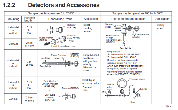
ZR22G detector directly measures oxygen/humidity in sample gas, universal type (sample temperature 0-700 ℃), high temperature type (0.15m probe, matched with ZO21P adapter, 0-1400 ℃); Probe length 0.15-5.4m (humidity analyzer does not include 0.15m)
ZR402G converter signal processing, display and control 320 × 240 point LCD touch screen; Power supply 100-240V AC; Support HART protocol; Output 4-20mA DC signal
2. Key auxiliary equipment
Calibration related: ZA8F flow setting unit (manual calibration), ZR40H automatic calibration unit (timed automatic calibration), ZO21S standard gas unit (simple calibration).
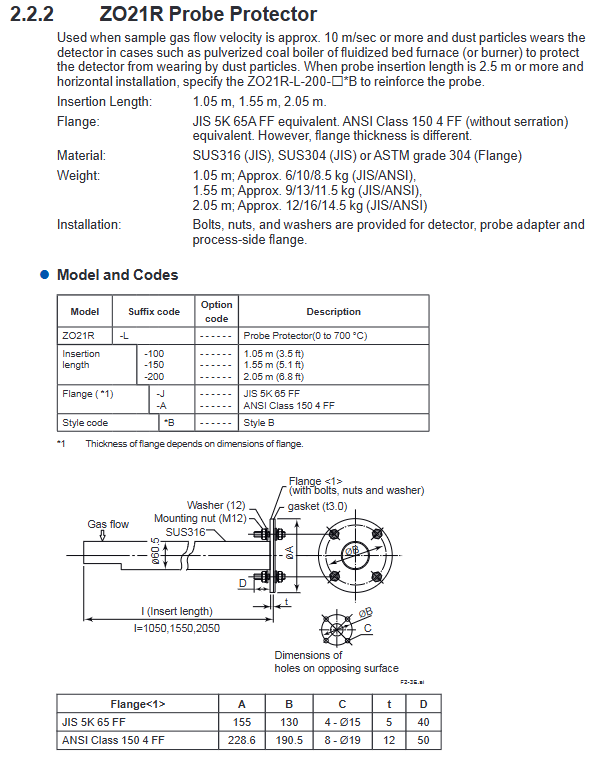
Protection related: ZO21R probe protector (anti dust wear), ZH21A dust protector (only for humidity analyzer), K9471UA detector dust filter (anti-corrosion dust).
High temperature adaptation: ZO21P high temperature probe adapter (compatible with ZR22G high temperature type, capable of withstanding 1400 ℃), E7046EC/EN high temperature auxiliary injector (for negative pressure scenarios).
3. Switching of oxygen/humidity analyzer
Oxygen analyzer: default configuration, ZR402G converter combined with ZR22G detector.
Humidity analyzer: Select the "/HS" option code for ZR402G, only supports specific probe lengths (excluding 0.15m), sample gas pressure limit -5 to 2kPa.
(3) Core technical parameters
Measurement type, measurement range, accuracy index, response time, output signal
Oxygen concentration 0.01-100 vol% O ₂ repeatability ± 0.5% -1% (depending on the range); Linear ± 1% -3% (based on range) 90% response ≤ 5 seconds 4-20mA DC (maximum load 550 Ω)
Humidity (volume fraction) 0-100 vol% H ₂ O repeatability ± 1 vol% H ₂ O (sample gas pressure ≤ 2kPa) - Same oxygen concentration output
Humidity (mixing ratio) 0-1.000 kg/kg - Same oxygen concentration output
System configuration and installation specifications
(1) Three standard system configurations
1. System 1 (Simple Monitoring)
Composition: ZR22G detector+ZR402G converter+ZO21S standard gas unit.
Applicable scenarios: simple scenarios such as small boiler oxygen concentration monitoring and food production humidity monitoring.
Features: No need to fix the reference airway, calibration gas is temporarily connected through a hose, easy to operate.
2. System 2 (Manual Precision Calibration)
Composition: Core components+ZA8F flow setting unit+zero gas cylinder+pressure reducing valve+air setting unit.
Applicable scenarios: Accurate control of oxygen/humidity in large boilers and heating furnaces.
Features: The reference air is clean and dry air (21 vol% O ₂), which supports manual precise adjustment of calibration air flow rate and higher measurement accuracy.
3. System 3 (Automatic Calibration)
Composition: Core components+ZR40H automatic calibration unit+combustible gas detection contacts.
Applicable scenarios: Large industrial furnaces and kilns that require long-term stable operation and reduced manual intervention.
Features: Automatic calibration is performed at preset intervals (up to 255 days), and the heater power is cut off when the combustible gas detection signal is triggered, providing higher safety.
(2) Installation Core Requirements
1. Environmental requirements
Detector: ambient temperature -20-150 ℃, no corrosive gas, no vibration, avoiding radiation heat effects.
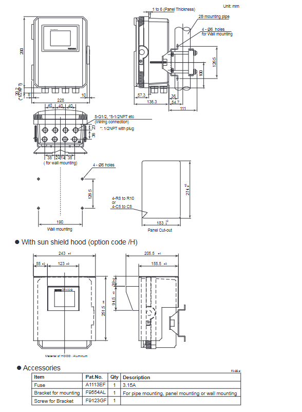
Converter: ambient temperature -20-55 ℃, humidity 0-95% RH (non condensing), away from direct sunlight (optional sunshade).
2. Installation specifications
Probe installation: When the length is ≤ 2m, it can be installed horizontally to vertically, and when it is ≥ 2.5m, it needs to be installed vertically (± 5 °); High temperature SiC probes must be installed vertically.
Flange specifications: Supports JIS, ANSI, DIN and other standards. During installation, it is necessary to ensure that the flange gasket does not block the reference gas outlet (pressure compensation type).
Protective measures: Dust environments require the installation of dust filters/protectors; Suitable probe adapters and injectors are required for high-temperature scenarios.
(3) Wiring specifications
1. Cable requirements
Detector signal: 6-core shielded cable (two-way resistance ≤ 10 Ω); Heater: 2-core cable; Temperature resistance ≥ 80 ℃.
Wiring principle: separate signal cables from power/heater cables to avoid interference; Shielding layer connected to converter FG terminal.
2. Key wiring types
Power and grounding: The converter supplies 100-240V AC power, and the protective grounding resistance is ≤ 100 Ω.
Detector connection: including sensor signal (CELL ±), thermocouple (TC ±), cold junction compensation (CJ ±), heater power supply (HTR) wiring.
External interfaces: analog output (4-20mA), contact input/output (control calibration, alarm, etc.), HART communication (refer to dedicated documentation).
Operation and Calibration Process
(1) Startup process
Pre inspection: Confirm that there is no leakage in the pipeline, the wiring is correct, and the valve status is normal.
Power supply startup: Connect the converter power supply, and the sensor begins to preheat (about 20 minutes, target temperature 750 ℃).
Parameter confirmation: Check the initial parameters such as converter type (oxygen/humidity), detector type, sample gas type (wet/dry gas), output range, etc.
Output inspection: Confirm that the current circuit (4-20mA) and contact I/O function are normal.
(2) Calibration operation (core process)
1. Calibration preparation
Gas requirements: Zero gas (0.95-1.0 vol% O ₂+N ₂), span gas (clean and dry air, dew point ≤ -20 ℃).
Flow setting: Calibrate air flow rate of 600 ± 60 ml/min, reference air flow rate of 800-1000 ml/min.
2. Calibration mode
Applicable scenarios for mode operation mode
Manual calibration is performed by manually controlling the gas valve through the ZO21S/ZA8F unit, and completing the calibration system 1/2 according to the touch screen prompts. Manual intervention is required
Semi automatic calibration of touch panel or touch input startup, completing calibration system 3 according to preset time, reducing manual operation
Automatic calibration is automatically executed at set intervals without the need for manual intervention. System 3 operates continuously for a long time
3. Core calibration steps
Span calibration: Introduce span gas and confirm calibration after the value stabilizes.
Zero calibration: Introduce zero gas and complete the calibration in the same way.
After calibration: Close the calibration gas valve and wait for the output to stabilize (default 10 minutes).
(3) Key parameter settings
1. Output settings
Oxygen analyzer: Set oxygen concentration values corresponding to 4mA (minimum range) and 20mA (maximum range), supporting linear or logarithmic output modes.
Humidity analyzer: Set the humidity (volume fraction or mixing ratio) corresponding to 4mA/20mA, and input the measured gas temperature and pressure to calculate the relative humidity and dew point.
2. Alarm setting
Supports four levels of alarms: high high, high, low, and low low. Alarm thresholds, hysteresis values (0-9.9 vol% O ₂, etc.), and delay times (0-255 seconds) can be set.
Alarm output: 4 contact outputs that can be assigned to alarm, fault, calibration, and other states.
Maintenance and troubleshooting
(1) Regular maintenance
1. Daily maintenance (recommended cycle)
Cleaning: Calibration gas pipeline (anti clogging), detector dust filter (K9471UA).
Inspection: Pipeline leakage, valve status, and cable connection tightness.
2. Regularly replace components
Precautions for component replacement
The zero gas calibration ratio of the sensor component exceeds 100 ± 30%, and the span gas calibration ratio exceeds 0 ± 18%; When the internal resistance of cells significantly increases, the metal O-ring (K9470BJ) and contact (E7042BS) must be replaced simultaneously
Abnormal resistance of heater unit (≤ 90 Ω is normal), unstable heating temperature at 750 ℃, please refer to the dedicated heater manual (IM 11M12A01-21E)
Before replacing the fuse converter with a blown fuse (specification 3.15A, Part No.A1113EF), it is necessary to investigate the short circuit fault
(2) Common faults and solutions
1. Error fault (Error code)
Key points for troubleshooting the causes of error codes and malfunctions
Error 1 Cell voltage fault (<-50mV) Check CELL ± wiring, sensor damage, internal wiring of detector
Error 2: Heater temperature fault (below 730 ℃ or above 780 ℃). Check the heater resistance, thermocouple wiring polarity, and cold end temperature (-25-155 ℃)
Error 3: The A/D converter has malfunctioned and restarted the device. If the error persists, please contact after-sales service
Error 4: Memory failure. Restart the device, but the error still persists. Contact after-sales service for assistance
2. Alarm fault (Alarm code)
Key points for troubleshooting the causes of alarm code faults
Alarm 6 zero calibration coefficient abnormality (exceeding 100 ± 30%) confirms zero gas concentration, calibration gas flow rate, and sensor contamination situation
Abnormal calibration coefficient of Alarm 7 span (exceeding 0 ± 18%) confirms span gas concentration, pipeline leakage, and sensor aging
Alarm 8 calibration stability timeout check calibration air flow rate, pipeline length/diameter, sensor response speed
Alarm 10 Cold End Temperature Abnormal (< -25 ℃ or > 155 ℃) Check the wiring of the cold end sensor and the ambient temperature of the detector
3. Abnormal measurement values
High measurement value (oxygen analyzer): reference gas humidity changes, calibration gas leakage, abnormal increase in sample pressure.
Low measurement value (oxygen analyzer): zero gas leakage, combustible components in sample gas, sensor damage.
Numerical fluctuations: loose wiring, electromagnetic interference, sensor cracks or installation leaks.
Safety and Compliance
(1) Key points for safe operation
Power safety: Confirm that the power supply voltage matches the rated value of the equipment, and disconnect the power before wiring.
High temperature protection: The working temperature of the detector probe reaches 750 ℃, and high-temperature resistant gloves should be worn during maintenance.
Gas safety: Calibration gas/sample gas may be toxic, ventilation or protective mask should be worn during maintenance, and the pipeline should be checked for leaks.
Sensor protection: The sensor is made of ceramic material to avoid impact and pressure, and direct contact with water droplets is prohibited.
(2) Compliance and Disposal
Identification compliance: CE/UKCA certified products must comply with the importer requirements of the corresponding region.
Waste disposal: Equipment must be disposed of in accordance with local environmental regulations; Batteries (lithium manganese dioxide batteries) need to be classified and recycled (EU/UK region).
Document compliance: The copyright of the manual belongs to Yokogawa Electric and cannot be copied or disseminated without permission.
Key accessories and spare parts
(1) Core attachments
Calibration related: Zero gas cylinder (G7001ZC), pressure reducing valve (G7013NF/G7014XF), calibration gas cylinder box (E7044KF).
Pipeline related: check valve (K9292DN/K9292DS), globe valve (L9852CB/G7016XH), pipe joint.
(2) List of commonly used spare parts
Spare part name, part number, and purpose
Sensor Component E7042UD/ZR01A01 Oxygen/Humidity Detection Core Component
Installation and sealing of metal O-ring K9470BJ sensor
Dust filter K9471UA detector dust protection
Fuse A1113EF converter power protection
Contact E7042BS sensor signal transmission
Document association and revision
(1) Related documents
General specification: GS 11M12A01-01E (ZR22G/402G/ZR202G series universal).
HART protocol: IM 11M12A01-51E (specifically for HART communication function).
Integrated device: IM 11M12A01-04E (sensor and analyzer integrated model).
Explosion proof type: IM 11M13A01-02E (specialized for ZR22S explosion-proof detector).
(2) Main revisions in the 18th edition
Add importer information related to CE/UKCA certification.
Revise RoHS compliance standards.
Supplement some flange dimensions and installation details.
- OMRON
- ABB
- General Electric
- EMERSON
- Honeywell
- HIMA
- ALSTOM
- Rolls-Royce
- MOTOROLA
- Rockwell
- Siemens
- Woodward
- YOKOGAWA
- FOXBORO
- KOLLMORGEN
- MOOG
- KB
- YAMAHA
- BENDER
- TEKTRONIX
- Westinghouse
- AMAT
- AB
- XYCOM
- Yaskawa
- B&R
- Schneider
- KONGSBERG
- NI
- WATLOW
- ProSoft
- SEW
- ADVANCED
- Reliance
- TRICONEX
- METSO
- MAN
- Advantest
- STUDER
- DANAHER MOTION
- Bently
- Galil
- EATON
- MOLEX
- DEIF
- B&W
- ZYGO
- Aerotech
- DANFOSS
- Beijer
- Moxa
- Rexroth
- Johnson
- WAGO
- TOSHIBA
- BMCM
- SMC
- HITACHI
- HIRSCHMANN
- Application field
- XP POWER
- CTI
- TRICON
- STOBER
- Thinklogical
- Horner Automation
- Meggitt
- Fanuc
- Baldor
- SHINKAWA
- Other Brands
- UniOP
- KUKA
- Iba
- Beckhoff
-
 Basler D90 96801 100 PCB Card
 -
 Basler XR2002F Voltage Regulator (110 VAC, 48-480 Hz)
 -
 Basler SR8A-2B14B3A Regulator
 -
 Basler 9561500100 Module
 -
 Basler DECS-400 BE1-11 System
 -
 Basler DECS-100-B15 Excitation Control
 -
 Basler SCP 210 Frequency Controller
 -
 Basler SR4A-2B15B3A Static Voltage Regulator
 -
 Basler BE1-32R Power Relay
 -
 Basler PIA2400-17GM Power Interface Adapter
 -
 Basler MVC 232 Manual Voltage Control Module
 -
 Basler SSR 32-12 Static Voltage Regulator
 -
 Basler 5MW AVR Generator Voltage Regulator
 -
 Basler VR63-4B Voltage Regulator
 -
 Basler DECS-100-A05 AVR for Engine Generator
 -
 Basler DECS-100-B15 Automatic Voltage Regulator
 -
 Basler BE1-32R Directional Power Relay
 -
 Basler BE1-87B Differential Relay
 -
 Basler UFOV 260A Protective Module
 -
 Basler 9-2614-02-100 PCB Rev M
 -
Basler DECS-100-B15 Digital AVR
-
 Basler 9284900103 PS DECS-400N
 -
 Basler D4N3H1U Intertie Protection
 -
 Basler DECS-100-B15 A15 AVR
 -
 Basler KR4F Voltage Regulator
 -
 Basler BE26434 T14 Transformer
 -
 Basler SR8A-2B15B3A Regulator
 -
 Westinghouse 774B472A12 AR Relay
 -
Basler DECS-100-B15 AVR
-
Basler XR2002F Regulator 110V
-
Basler SR125-E Static Regulator
-
 Basler SSR 125-12 Regulator
 -
 Basler MOC2599 Motor Pot
 -
 Basler BE1-DFPR Feeder Relay
 -
 Basler CBS 305 Current Boost
 -
 Basler BE1-25 AutoSync
 -
 Basler MVC 300 Voltage Control
 -
 Basler BE3-25A AutoSync
 -
 Basler KR7FF Static Regulator
 -
 Basler 90-49000-100 Regulator
 -
 Basler 880 kVA Dry Type Transformer Specs
 -
 Basler Electric BE1-25 Sync-Check Relay Specs
 -
 Basler SSR 125-12 Voltage Regulator Specs
 -
 Basler Electric BE1-851 Overcurrent Relay Review
 -
Basler Electric 149D930G02 Control Sub-Assembly
-
 Basler Electric BE1-81O/UT Frequency Relay Specs
 -
 Basler Electric BE1-51/27C Overcurrent Relay
 -
 Basler Electric 149D956G02 Industrial Component
 -
Basler Electric BE1-51A Overcurrent Relay Specs
-
 Basler Electric BE1-40Q Loss of Excitation Relay
 -
 Basler DECS-200 Excitation Control System
 -
 Basler DECS-200 Voltage Regulator 56-277V AC / 125V DC
 -
Basler BE1-87T Transformer Differential Relay
-
 Basler RDP-110-S1 Protection Relay
 -
 Basler BE1-700V Digital Protective Relay
 -
 Basler BE1-951 Overcurrent Protection System
 -
 Basler DECS-300 Digital Excitation Control
 -
 Basler DECS-200 Digital Excitation Control
 -
 Basler DECS-200-1C Excitation Control System
 -
Basler DECS-200-1L Digital Excitation Control
-
 Basler Electric BE1-GPS Generator Protection System
 -
Basler Electric DECS-200-1C Digital Excitation Controller
-
 Basler Electric DECS125-15 Excitation Control with Power Module
 -
 Basler Electric BE1-87G Differential Relay
 -
 Basler Electric BE1-11 Protection System I5A3M2P2N0EA00
 -
Basler Electric DECS-200-1C Excitation Control System
-
Basler Electric BE1-11g Generator Protection Relay
-
Basler Electric DECS 125-15-B2C1 V2.0.9 Excitation Control
-
 Basler Electric BE1-81O/UT3ED1JA7N2F Frequency Relay
 -
Basler Electric BE1-81O/UT3EE1YB7N1F Frequency Relay
-
 Basler Electric DECS-200-1L Digital Excitation Control System
 -
Basler DECS125-15-B2C1 Excitation Control
-
 Basler 9507900205 SSR Retrofit Voltage Regulator
 -
 Basler BE2000E Digital Voltage Regulator
 -
 Basler BE1-GPS Generator Protection System
 -
Basler DECS-250-CN1CN1N Digital Excitation Control
-
 Basler DGC-2020 Genset Controller
 -
 Basler BE1-81O UT3ED1LA7N0F Frequency Relay (Variant)
 -
 Basler BE1-81O UT3EE1YA9S0F Frequency Relay (Variant)
 -
Basler BE1-81O Over/Under Frequency Relay
-
Basler DECS125-15 Digital Excitation Control
-
Basler Electric BE1-951 Overcurrent Protection System
-
 Basler Electric BE1-700V Digital Protective Relay
 -
 Basler Electric APR63-5 Automatic Voltage Regulator
 -
Basler Electric BE1-851 Overcurrent Protection System
-
Basler Electric DECS-250-LN1SN1N Excitation Control
-
 Basler Electric BE1-87T Transformer Differential Relay
 -
Basler Electric DECS-200-1L Excitation Control System
-
 Basler Electric 9310300100 DECS-300 Excitation Control
 -
 Basler Electric SSE-N 125-4.5KW Shunt Exciter Regulator
 -
 Basler Electric DGC-2020HD-5NS1DNSBA Genset Controller
 -
Basler Electric BE1-81-O/UT3EE1JB7N1F Frequency Relay
-
Basler Electric BE1-81T1EE1WA0N1F Frequency Relay
-
 Basler Electric BE1-25M1EA6PN5R1F Sync-Check Relay
 -
 Basler Electric BE1-GPS Generator Protection System
 -
Basler Electric DECS-250-LN1SN1N Excitation Control Rev V
-
 Basler Electric DECS-250-CN2CN1N Excitation Control
 -
Basler Electric BE1-50/51B-207 Overcurrent Relay
-
Basler Electric DECS-300-C0N0 Excitation Control System
-
Basler Electric DECS-200 Digital Excitation Control System
-
Basler Electric DECS-250-LN1CN1N Excitation Unit
-
Basler Electric DECS-250 LN2SA1D Excitation Unit Specs
-
Basler Electric BE1-87T Transformer Relay Review
-
Basler Electric BE1-11 Protection System
-
Basler Electric BE1-GPS100-E4N1H1N Protection System
-
 Allen-Bradley 442G-MABH-R Safety Module
 -
 Beckhoff CX1030-0111 PLC Assembly Profile
 -
 FANUC IC693CPU364 PLC Module
 -
 Orange Denmark Type 200816 220 PLC Specs
 -
 OMRON C200H-SNT31 Sysmac PLC Module
 -
 Allen Bradley 20AB022A3AYNANC0 PowerFlex 70
 -
 OMRON C200HW-PCU01 Position Control Unit
 -
 ABB AO845A-eA Analog Output Module
 -
 OMRON CJ1M-CPU22 CPU Unit
 -
 Allen Bradley 100-E265ED11 Contactor
 -
 Honeywell 51304511-100 Interface Module
 -
 SOLEXY BXF3S0101N0018 Gateway Module
 -
 OMRON CJ2H-CPU65 CPU Unit
 -
 Automation Direct GS2-45P0 AC Drive
 -
 M68-2000 2-Axis Motion CNC Controller
 -
 OMRON CJ1M-CPU11 V3.0 PLC CPU Unit
 -
 OMRON CJ1W-NC413 4-Axis Positioning Controller
 -
 OMRON 3G2A3-PRO16 Programming Console HMI
 -
 Siemens 3VT8440-2AA04-2GA2 Molded Case Circuit Breaker
 -
 Siemens 3RT5045 Contactor Series
 -
 OMRON C200HS-CPU01-E SYSMAC PLC Controller
 -
 OMRON C500-NC103-E Positioning Control Unit
 -
 OMRON CJ1W-TC001 Temperature Control Unit


