
YOKOGAWA built-in isolation barrier I/O module (FIO specific)
YOKOGAWA built-in isolation barrier I/O module (FIO specific)
Module classification and core technical parameters
(1) Analog module (including HART communication version)
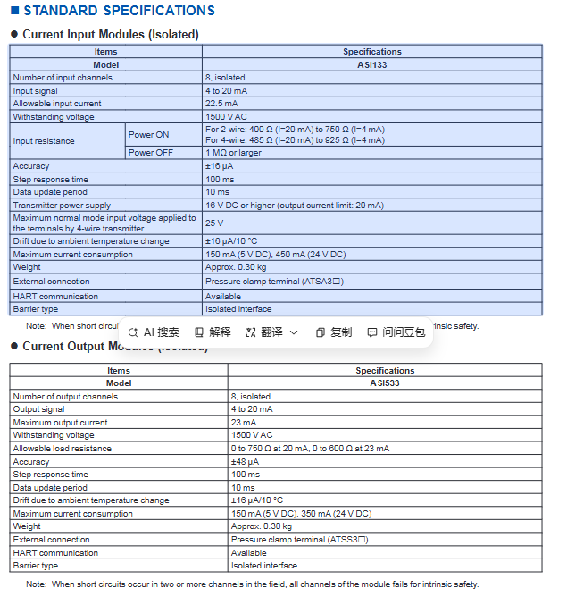
1. Analog input module (ASI133/ASI133-H)
Project specifications
Number of channels: 8 channels, module level galvanic isolation, no isolation between channels
Input signal 4-20mA DC, supports 2-wire/4-wire transmitters
Allow input current of 22.5mA
Withstand voltage strength 1500V AC
Input resistance (energized) 2-wire system: 400 Ω (20mA)~750 Ω (4mA); 4-wire system: 485 Ω (20mA)~925 Ω (4mA)
Input resistance (power-off) ≥ 1M Ω
Accuracy (23 ℃) ± 16 µ A
Temperature drift ± 16 µ A/10 ℃
Step response time 100ms
Data update cycle 10ms
Transmitter power supply above 16V DC, output current limited to 20mA
4-wire transmitter maximum common mode input voltage 25V
Current consumption 5V DC: 150mA; 24V DC:450mA
Weight approximately 0.30kg
External connection pressure clamp terminal (ATSA3S single redundancy/ATSA3D dual redundancy)
HART communication (ASI133-H) supports HART Protocol Revision 5.71200bps rate
Explosion proof feature: When a multi-channel short circuit occurs, the overall explosion-proof function of the module fails
2. Analog output module (ASI533/ASI533-H)
Project specifications
Number of channels: 8 channels, module level galvanic isolation, no isolation between channels
Output signal 4-20mA DC
Maximum output current 23mA
Withstand voltage strength 1500V AC
Allow 0-750 Ω when the load resistance is 20mA; 0-600 Ω at 23mA
Accuracy (23 ℃) ± 48 µ A
Temperature drift ± 16 µ A/10 ℃
Step response time 100ms
Data update cycle 10ms
Current consumption 5V DC: 150mA; 24V DC:350mA
Weight approximately 0.30kg
External connection pressure clamp terminal (ATSS3S single redundancy/ATSS3D dual redundancy)
HART communication (ASI533-H) supports HART Protocol Revision 5.7, with a maximum of 5 devices/channel connected to multiple stations
Explosion proof feature: When a multi-channel short circuit occurs, the overall explosion-proof function of the module fails
(2) Temperature input module
1. TC/mV input module (AST143)
Project specifications
16 channels, module level galvanic isolation, no isolation between channels
Input signal TC: IEC 60584-1 (ITS-90) Type B/E/J/K/N/R/S/T; mV:-100~150mV、-50~75mV
Signal switching CH1-CH16 can be set as TC or mV input respectively
Allow input voltage ± 5V
Withstand voltage strength 1500V AC
Input resistance (on/off) ≥ 1M Ω
Accuracy (23 ℃) TC: ± 40 µ V; mV: ± 80 µ V
The allowable total resistance of the signal source and wiring is ≤ 1000 Ω
Reference compensation accuracy ± 1 ℃ at 15-45 ℃; -± 2 ℃ at 20-15 ℃/45-70 ℃
Temperature drift TC: ± 125 µ V/10 ℃; mV:±250µV/10℃
Data update cycle ≤ 1 second
The burn off function can be uniformly set for all channels (enabled/disabled, UP/DOWN)
Current consumption 5V DC: 150mA; 24V DC:80mA
Weight approximately 0.30kg
External connection pressure clamp terminal (ATST4S single redundancy/ATST4D dual redundancy)
Special requirements require the use of non grounded thermocouples; Type B has no temperature compensation and cannot be measured below 44 ℃
2. RTD/BOT input module (ASR133)
Project specifications
Number of channels: 8 channels, module level galvanic isolation, no isolation between channels
Input signal RTD: 2/3/4 wire system (Pt50/Pt100/Pt200/Pt500/Pt1000/Ni100/Ni200/Ni120); POT: 3-wire system 0-10k Ω
Signal switching CH1-CH8 can select RTD or POT input respectively
Allow input voltage ± 5V
Withstand voltage strength 1500V AC
Input resistance (on/off) ≥ 1M Ω
Accuracy (23 ℃) Pt50/Pt100/Ni100/Ni200/Ni120: ± 150m Ω; Pt200: ± 300m Ω; Pt500: ± 600m Ω; Pt1000: ± 1.2 Ω; POT:±2Ω
Measure current of 150 µ A
Temperature drift Pt50/Pt100/Ni100/Ni200/Ni120: ± 325m Ω/10 ℃; Pt200:±650mΩ/10℃; Pt500:±1.3Ω/10℃; Pt1000:±2.6Ω/10℃; POT:±5.2Ω/10℃
Data update cycle ≤ 1 second
Current consumption 5V DC: 150mA; 24V DC:60mA
Weight approximately 0.30kg
External connection pressure clamp terminal (ATSR3S single redundancy/ATSR3D dual redundancy)
(3) Digital module
1. Digital input module (ASD143)
Project specifications
16 channels, module level galvanic isolation, no isolation between channels
NAMUR compatible input signal (IEC 60947-5-6)
Withstand voltage strength 1500V AC
Response characteristic state input response time 15ms; button input minimum ON detection time 20ms, maximum ON/OFF cycle 25Hz
Current consumption 5V DC: 150mA; 24V DC:110mA
Weight approximately 0.30kg
External connection pressure clamp terminal (ATSB4S single redundancy/ATSB4D dual redundancy)
Explosion proof feature: When a multi-channel short circuit occurs, the overall explosion-proof function of the module fails
2. Digital output module (ASD533)
Project specifications
Number of channels: 8 channels, module level galvanic isolation, no isolation between channels
12V at 40mA output signal; 26V at 0mA output signal
Withstand voltage strength 1500V AC
Output response time 10ms
Current consumption 5V DC: 150mA; 24V DC:500mA
Weight approximately 0.30kg
External connection pressure clamp terminal (ATSD3S single redundancy/ATSD3D dual redundancy)
Explosion proof feature: When a multi-channel short circuit occurs, the overall explosion-proof function of the module fails
Explosion proof parameters and certification
(1) ATEX certification parameters (core module)
Module model, configuration type Uo(V) Io(mA) Po(mW) Co(nF)(IIC/IIB/IIA) Lo(mH)(IIC/IIB/IIA) remark
ASI133-S00/H00 single redundancy (2-wire system) 27.8 84 584 84/659/18/18-
ASI133-S00/H00 single redundancy (4-wire system) 27.8 4 28 84/659/659 100/100/100-
ASI133-S00/H00 dual redundancy (2-wire system) 27.8 93 647 84/659/659 1.2/14/14-
AST143-S00 Single Redundancy (Single Channel) 16.8 7 30 220/1730/8000 240/725/1930 No equipotential connection
AST143-S00 single redundancy (multi-channel) 16.8 46 194 65/380/1550 5.6/22/44 2-channel to full channel equipotential connection
ASD143-P00 single redundancy 9.8 21 52 1100/7600/11600 26/107/214-
ASD533-S00 single redundancy 27.16 108.6 738 89/690/690 0.42/9.9/9.9-
(2) FM authentication parameters (core module)
Module model, configuration type Voc(V) Isc(mA) Po(mW) Ca(nF)(A,B/C,E/D,F,G) La(mH)(A,B/C,E/D,F,G)
ASI133-S00/H00 single redundancy (2-wire system) 27.8 84 584 84/659/18/18
ASI133-S00/H00 single redundancy (4-wire system) 27.8 4 28 84/659/659 100/100/100
AST143-S00 Single Redundancy (Single Channel) 16.8 7 30 220/1730/8000 240/725/1930
ASD143-P00 single redundancy 9.8 21 52 1100/7600/11600 26/107/214
ASD533-S00 single redundancy 27.16 108.6 738 89/690/690 0.42/9.9/9.9
Detailed explanation of HART communication function
(1) Core specifications
Communication mode: Serial half duplex, start stop synchronization (1-bit start/8-bit data/1-bit odd parity/1-bit stop)
Applicable standard: HART Protocol Revision 5.7 (compatible with HART 5/6/7 devices)
Transmission rate: 1200bps ± 1%
Modulation method: Binary phase continuous FSK (1:1200Hz ± 1%); 0:2200Hz±1%)
Frame length: 5-267 bytes (including address, command, data, and checksum bytes)
Response time: Maximum 28 characters (256.7ms)
No response timer: Main device 33 characters (305ms); From device 41 characters (380ms)
(2) Connection and Data Characteristics
Device connection: up to 16 devices/modules; Multiple station connections up to 5 units/channel (input devices only)
Data processing: The maximum number of HART variables per module is 32 points, connected through the% Z terminal, and only supports input
Data refresh cycle: 1 second per device (17 seconds per ESB bus connection for 16 devices)
System configuration: Supports dual redundancy, requiring two modules to be installed in adjacent slots (odd+even) of the same node unit
(3) Data flow
The module communicates with on-site HART devices to collect analog data and HART variables;
Data is stored in the I/O image area of the module;
FCS reads I/O image area data through access modules;
FCS calls data through functional block I/O terminals and processes it uniformly with ordinary analog/digital signals.
Installation and compatibility requirements
(1) Hardware compatibility
1. On site Control Unit (FCU)
Compatible models: AFV30D-S41 11, AFV30S-S31-11, AFV30S-341 11
Power requirements: PW481-11, PW482-11, or PW484-11 power modules are required
2. Node unit
ESB bus node units: ANB10D-4 1, ANB10S-3 1, ANB10S-4 1, ANB10D-4 3, ANB10S-3 3, ANB10S-4 3
Optical ESB bus node units: ANB11D-2 3, ANB11D-4 3, ANB11S-1 3, ANB11S-2 3, ANB11S-3 3, ANB11S-4 3
(2) Software and Engineering Requirements
Control function: VP6F1700 on-site control station control function (applicable to AFV30 )
Engineering Tool: VP6E5100 Standard Builder Function
EMC requirement: Shielded cables are required (one layer of shielding can be shared across all channels)
(3) Installation precautions
Redundant configuration: Dual redundant modules need to be installed in adjacent slots (odd+even), and the terminals should use dual redundant pressure clamp terminals
Wiring requirements: Separate the wiring of analog signals and digital signals to avoid interference; The resistance of thermocouple wiring needs to be consistent
Environmental restrictions: Operating temperature -20 to 70 ℃, avoid direct sunlight and corrosive gases
Explosion proof isolation: The distance between non intrinsic safety modules should be ≥ 50mm, and insulation partitions should be installed (refer to the relevant explosion-proof document)
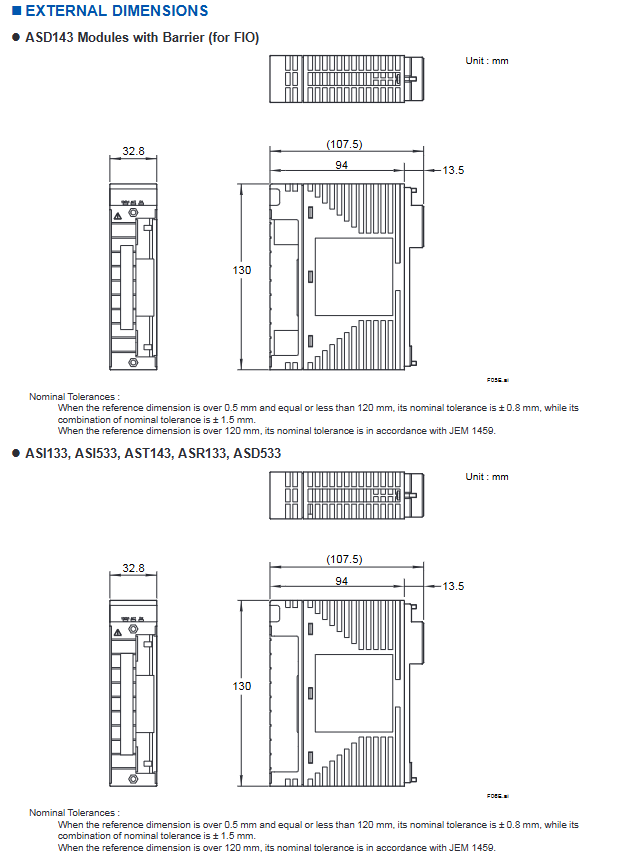
Module size and model code
(1) External dimensions (unit: mm)
Module type, width, height, depth, protrusion length, tolerance standard
ASD143 32.8 130 94 13.5 0.5-120mm: ± 0.8mm; combination tolerance ± 1.5mm; > 120mm: follow JEM 1459
Other modules (ASI133/533, AST143, ASR133, ASD533) 32.8 130 94 13.5 Same as above
(2) Model coding rules
1. Analog Input Module (ASI133)
Basic model: ASI133 (8-channel, 4-20mA, built-in isolation barrier)
Suffix codes: - S (standard type), - H (with HART communication), 00 (fixed position)
Option codes:/SA3S0 (single redundant pressure clamp terminal),/SA3D0 (dual redundant pressure clamp terminal)
2. Analog output module (ASI533)
Basic model: ASI533 (8-channel, 4-20mA, built-in isolation barrier)
Suffix codes: - S (standard type), - H (with HART communication), 00 (fixed position)
Option codes:/SS3S0 (single redundant pressure clamp terminal),/SS3D0 (dual redundant pressure clamp terminal)
3. TC/mV input module (AST143)
Basic model: AST143 (16 channels, TC/mV input, built-in isolation barrier)
Suffix code: - S (standard type), 00 (fixed position)
Option codes:/T4S0 (single redundant pressure clamp terminal),/T4D0 (dual redundant pressure clamp terminal)
4. RTD/BOT input module (ASR133)
Basic model: ASR133 (8-channel, RTD/BOT input, built-in isolation barrier)
Suffix code: - S (standard type), 00 (fixed position)
Option codes:/SR3S0 (single redundant pressure clamp terminal),/SR3D0 (dual redundant pressure clamp terminal)
5. Digital Input Module (ASD143)
Basic model: ASD143 (16 channels, NAMUR compatible, built-in isolation barrier)
Suffix code: - P (standard type), 00 (fixed position)
Option codes:/SB4S0 (single redundant pressure clamp terminal),/SB4D0 (dual redundant pressure clamp terminal)
6. Digital output module (ASD533)
Basic model: ASD533 (8-channel, digital output, built-in isolation barrier)
Suffix code: - S (standard type), 00 (fixed position)
Option codes:/SD3S0 (single redundant pressure clamp terminal),/SDD30 (dual redundant pressure clamp terminal)
- OMRON
- ABB
- General Electric
- EMERSON
- Honeywell
- HIMA
- ALSTOM
- Rolls-Royce
- MOTOROLA
- Rockwell
- Siemens
- Woodward
- YOKOGAWA
- FOXBORO
- KOLLMORGEN
- MOOG
- KB
- YAMAHA
- BENDER
- TEKTRONIX
- Westinghouse
- AMAT
- AB
- XYCOM
- Yaskawa
- B&R
- Schneider
- KONGSBERG
- NI
- WATLOW
- ProSoft
- SEW
- ADVANCED
- Reliance
- TRICONEX
- METSO
- MAN
- Advantest
- STUDER
- DANAHER MOTION
- Bently
- Galil
- EATON
- MOLEX
- DEIF
- B&W
- ZYGO
- Aerotech
- DANFOSS
- Beijer
- Moxa
- Rexroth
- Johnson
- WAGO
- TOSHIBA
- BMCM
- SMC
- HITACHI
- HIRSCHMANN
- Application field
- XP POWER
- CTI
- TRICON
- STOBER
- Thinklogical
- Horner Automation
- Meggitt
- Fanuc
- Baldor
- SHINKAWA
- Other Brands
- UniOP
- KUKA
- Iba
- Beckhoff
-
 Basler D90 96801 100 PCB Card
 -
 Basler XR2002F Voltage Regulator (110 VAC, 48-480 Hz)
 -
 Basler SR8A-2B14B3A Regulator
 -
 Basler 9561500100 Module
 -
 Basler DECS-400 BE1-11 System
 -
 Basler DECS-100-B15 Excitation Control
 -
 Basler SCP 210 Frequency Controller
 -
 Basler SR4A-2B15B3A Static Voltage Regulator
 -
 Basler BE1-32R Power Relay
 -
 Basler PIA2400-17GM Power Interface Adapter
 -
 Basler MVC 232 Manual Voltage Control Module
 -
 Basler SSR 32-12 Static Voltage Regulator
 -
 Basler 5MW AVR Generator Voltage Regulator
 -
 Basler VR63-4B Voltage Regulator
 -
 Basler DECS-100-A05 AVR for Engine Generator
 -
 Basler DECS-100-B15 Automatic Voltage Regulator
 -
 Basler BE1-32R Directional Power Relay
 -
 Basler BE1-87B Differential Relay
 -
 Basler UFOV 260A Protective Module
 -
 Basler 9-2614-02-100 PCB Rev M
 -
Basler DECS-100-B15 Digital AVR
-
 Basler 9284900103 PS DECS-400N
 -
 Basler D4N3H1U Intertie Protection
 -
 Basler DECS-100-B15 A15 AVR
 -
 Basler KR4F Voltage Regulator
 -
 Basler BE26434 T14 Transformer
 -
 Basler SR8A-2B15B3A Regulator
 -
 Westinghouse 774B472A12 AR Relay
 -
Basler DECS-100-B15 AVR
-
Basler XR2002F Regulator 110V
-
Basler SR125-E Static Regulator
-
 Basler SSR 125-12 Regulator
 -
 Basler MOC2599 Motor Pot
 -
 Basler BE1-DFPR Feeder Relay
 -
 Basler CBS 305 Current Boost
 -
 Basler BE1-25 AutoSync
 -
 Basler MVC 300 Voltage Control
 -
 Basler BE3-25A AutoSync
 -
 Basler KR7FF Static Regulator
 -
 Basler 90-49000-100 Regulator
 -
 Basler 880 kVA Dry Type Transformer Specs
 -
 Basler Electric BE1-25 Sync-Check Relay Specs
 -
 Basler SSR 125-12 Voltage Regulator Specs
 -
 Basler Electric BE1-851 Overcurrent Relay Review
 -
Basler Electric 149D930G02 Control Sub-Assembly
-
 Basler Electric BE1-81O/UT Frequency Relay Specs
 -
 Basler Electric BE1-51/27C Overcurrent Relay
 -
 Basler Electric 149D956G02 Industrial Component
 -
Basler Electric BE1-51A Overcurrent Relay Specs
-
 Basler Electric BE1-40Q Loss of Excitation Relay
 -
 Basler DECS-200 Excitation Control System
 -
 Basler DECS-200 Voltage Regulator 56-277V AC / 125V DC
 -
Basler BE1-87T Transformer Differential Relay
-
 Basler RDP-110-S1 Protection Relay
 -
 Basler BE1-700V Digital Protective Relay
 -
 Basler BE1-951 Overcurrent Protection System
 -
 Basler DECS-300 Digital Excitation Control
 -
 Basler DECS-200 Digital Excitation Control
 -
 Basler DECS-200-1C Excitation Control System
 -
Basler DECS-200-1L Digital Excitation Control
-
 Basler Electric BE1-GPS Generator Protection System
 -
Basler Electric DECS-200-1C Digital Excitation Controller
-
 Basler Electric DECS125-15 Excitation Control with Power Module
 -
 Basler Electric BE1-87G Differential Relay
 -
 Basler Electric BE1-11 Protection System I5A3M2P2N0EA00
 -
Basler Electric DECS-200-1C Excitation Control System
-
Basler Electric BE1-11g Generator Protection Relay
-
Basler Electric DECS 125-15-B2C1 V2.0.9 Excitation Control
-
 Basler Electric BE1-81O/UT3ED1JA7N2F Frequency Relay
 -
Basler Electric BE1-81O/UT3EE1YB7N1F Frequency Relay
-
 Basler Electric DECS-200-1L Digital Excitation Control System
 -
Basler DECS125-15-B2C1 Excitation Control
-
 Basler 9507900205 SSR Retrofit Voltage Regulator
 -
 Basler BE2000E Digital Voltage Regulator
 -
 Basler BE1-GPS Generator Protection System
 -
Basler DECS-250-CN1CN1N Digital Excitation Control
-
 Basler DGC-2020 Genset Controller
 -
 Basler BE1-81O UT3ED1LA7N0F Frequency Relay (Variant)
 -
 Basler BE1-81O UT3EE1YA9S0F Frequency Relay (Variant)
 -
Basler BE1-81O Over/Under Frequency Relay
-
Basler DECS125-15 Digital Excitation Control
-
Basler Electric BE1-951 Overcurrent Protection System
-
 Basler Electric BE1-700V Digital Protective Relay
 -
 Basler Electric APR63-5 Automatic Voltage Regulator
 -
Basler Electric BE1-851 Overcurrent Protection System
-
Basler Electric DECS-250-LN1SN1N Excitation Control
-
 Basler Electric BE1-87T Transformer Differential Relay
 -
Basler Electric DECS-200-1L Excitation Control System
-
 Basler Electric 9310300100 DECS-300 Excitation Control
 -
 Basler Electric SSE-N 125-4.5KW Shunt Exciter Regulator
 -
 Basler Electric DGC-2020HD-5NS1DNSBA Genset Controller
 -
Basler Electric BE1-81-O/UT3EE1JB7N1F Frequency Relay
-
Basler Electric BE1-81T1EE1WA0N1F Frequency Relay
-
 Basler Electric BE1-25M1EA6PN5R1F Sync-Check Relay
 -
 Basler Electric BE1-GPS Generator Protection System
 -
Basler Electric DECS-250-LN1SN1N Excitation Control Rev V
-
 Basler Electric DECS-250-CN2CN1N Excitation Control
 -
Basler Electric BE1-50/51B-207 Overcurrent Relay
-
Basler Electric DECS-300-C0N0 Excitation Control System
-
Basler Electric DECS-200 Digital Excitation Control System
-
Basler Electric DECS-250-LN1CN1N Excitation Unit
-
Basler Electric DECS-250 LN2SA1D Excitation Unit Specs
-
Basler Electric BE1-87T Transformer Relay Review
-
Basler Electric BE1-11 Protection System
-
Basler Electric BE1-GPS100-E4N1H1N Protection System
-
 Allen-Bradley 442G-MABH-R Safety Module
 -
 Beckhoff CX1030-0111 PLC Assembly Profile
 -
 FANUC IC693CPU364 PLC Module
 -
 Orange Denmark Type 200816 220 PLC Specs
 -
 OMRON C200H-SNT31 Sysmac PLC Module
 -
 Allen Bradley 20AB022A3AYNANC0 PowerFlex 70
 -
 OMRON C200HW-PCU01 Position Control Unit
 -
 ABB AO845A-eA Analog Output Module
 -
 OMRON CJ1M-CPU22 CPU Unit
 -
 Allen Bradley 100-E265ED11 Contactor
 -
 Honeywell 51304511-100 Interface Module
 -
 SOLEXY BXF3S0101N0018 Gateway Module
 -
 OMRON CJ2H-CPU65 CPU Unit
 -
 Automation Direct GS2-45P0 AC Drive
 -
 M68-2000 2-Axis Motion CNC Controller
 -
 OMRON CJ1M-CPU11 V3.0 PLC CPU Unit
 -
 OMRON CJ1W-NC413 4-Axis Positioning Controller
 -
 OMRON 3G2A3-PRO16 Programming Console HMI
 -
 Siemens 3VT8440-2AA04-2GA2 Molded Case Circuit Breaker
 -
 Siemens 3RT5045 Contactor Series
 -
 OMRON C200HS-CPU01-E SYSMAC PLC Controller
 -
 OMRON C500-NC103-E Positioning Control Unit
 -
 OMRON CJ1W-TC001 Temperature Control Unit


