
TRLC0NEX Tricon fault-tolerant controller
TRLC0NEX Tricon fault-tolerant controller
Product core positioning and fault tolerance principle
1. Core Definition
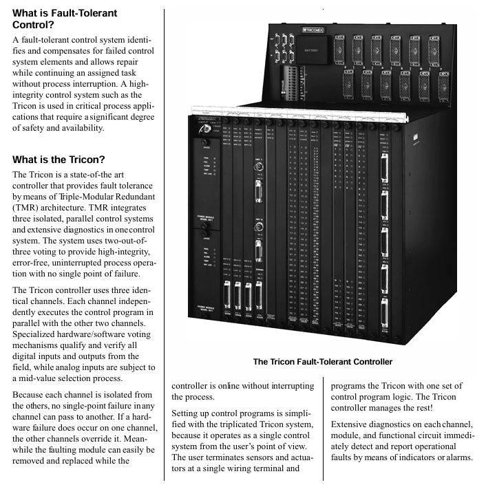
Tricon is a fault-tolerant controller designed for safety critical industrial scenarios. It uses a triple modular redundancy (TMR) architecture to achieve fault detection, compensation, and online maintenance, ensuring uninterrupted process control. It is suitable for industrial environments with extremely high requirements for safety and availability.
2. Fault tolerant core mechanism
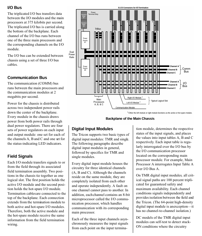
Architecture design: The system is fully triple from input module, main processor to output module, with three independent channels (A/B/C) running in parallel and communicating synchronously through a proprietary TriBus bus.
Data processing rules: The "two out of three" voting mechanism is used for digital input/output, and the median selection method is used for analog input to ensure that erroneous data is blocked.
Fault handling: When a single channel fails, the other channels automatically take over control, and the faulty module can be plugged and replaced online without stopping the machine.
Diagnostic capability: Each channel, module, and functional circuit is equipped with comprehensive diagnostic functions, which provide real-time feedback on faults through indicator lights or alarm signals. Diagnostic data can be called by control programs or operators.
3. Core advantages
No single point of failure design, supports 3/2/1 main processor (MP) operation mode, ensuring that operation can still be maintained in extreme situations.
Remote I/O supports transmission up to 7.5 miles (12 kilometers), suitable for large-scale industrial scene layouts.
The full range of I/O modules covers digital, analog, pulse, thermocouple and other signal types, supporting dual module or single module configurations, balancing safety and cost requirements.
Continuous operation and online maintenance capabilities significantly improve system availability.
System hardware composition and specifications
1. Core hardware components
(1) Main Processor Module (MP)
Model: Model 3008 (suitable for v9.6 and above systems), equipped with 16MB DRAM, 32KB spare SRAM, and 6MB Flash PROM.
Core chip: Motorola MPC860 32-bit processor, with a main frequency of 50MHz, TriBus communication rate of 25Mbps, and support for DMA synchronous transmission.
Power protection: Powered by dual power modules, the program and hold variables can maintain integrity for at least 6 months after power failure.
Indicator lights: including status indicators such as PASS (self-test pass), FAILT (fault), ACTION (running), etc.
(2) Power module
Configuration: Each chassis is equipped with 2 redundant power modules that support hot swapping, and a single module can meet the power supply needs of the entire chassis.
Input specifications: Available in 24VDC, 115VAC, and 230VAC versions, with input voltage ranges of 22-31VDC, 85-140VAC, and 185-285VAC, respectively.
Output parameters: 175 watts (at 60 ° C environment), output voltage 6.5VDC ± 1%, maximum output current 27A.
Protection function: Built in over temperature (triggered at 83 ° C), low battery, overvoltage/undervoltage diagnosis, supports alarm contact output.
(3) I/O module
Covering types such as digital input/output, analog input/output, pulse input/accumulator, thermocouple input, etc., the core specifications are as follows:
Example of key parameters for module types and typical models
TMR digital input voltage range is 24/48/115VAC/VDC, with 32/64 points, supporting self-test testing for 3501E/3503E/3504E
Single channel digital input 24VDC, 64 points, optimized cost type, triple critical path 3564
TMR digital output voltage range 24/48/120VDC, 115VAC, with 8/16/32 points, supporting voting and circuit diagnosis 3604E/3624/3611E
Analog input supports 0-5/0-10VDC, 4-20mA, thermocouple (J/K/T/E), 12/14 bit resolution, isolated/non isolated versions 3703E/3708E/3721
Analog output 4-20mA (8 points) or 4-20mA+20-320mA (high current version), accuracy ± 0.25% FSR 3505E/3806E
Pulse module frequency range 20Hz-20kHz (input), 0-1kHz (cumulative), supports speed and flow measurement 3511 (input)/3515 (cumulative)
(4) Communication module
Provide multiple types of communication interfaces, supporting interconnection with Modbus devices, DCS systems, Ethernet hosts, etc. The core models are as follows:
Module Name Communication Protocol/Interface Core Function Model
TCM (Tricon Communication Module) Ethernet (802.3), RS-232/485 supports Modbus TCP, Peer to Peer, GPS timing 4351A/4352A/4353
EICM (Enhanced Intelligent Communication Module) RS-232/422/485, parallel port Modbus master/slave communication, supports printer connection 4119/4119A
NCM (Network Communication Module) Ethernet (802.3) supports OPC Server, TSAA protocol, GPS synchronization 4329/4329G
SMM (Safety Manager Module) Honeywell UCN bus docking with TDC 3000 DCS, safety node communication 4409
ACM (Advanced Communication Module) Foxboro I/A Nodebus interfaces with Foxboro DCS and supports TriStation protocol 4609
HIM (Hiway Interface Module) Honeywell Data Hiway/LCN docking with TDC 3000/2000 DCS 4509
RXM (Remote Expansion Module) multi-mode/single-mode fiber remote I/O expansion, capable of transmitting up to 12 kilometers from 4200-3/4210-3 (main) to 4201-3/4211-3 (slave)
2. System chassis configuration
(1) Chassis type and layout
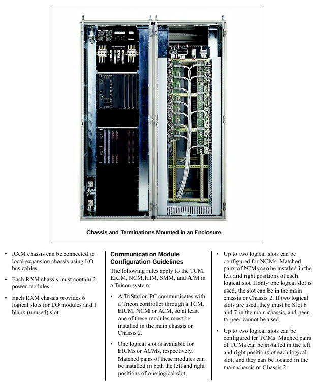
Main chassis (Model 8110): accommodates 3 main processors, 2 power modules, and provides 6 logic slots (including hot spare positions)+1 COM slot.
Expansion chassis (Model 8111): No main processor, provides 8 logical slots, suitable for expansion within 100 feet (30 meters), and can be extended up to 1000 feet in restricted scenarios.
Remote Expansion Chassis (Model 8112): Equipped with RXM module, supporting fiber optic transmission, suitable for ultra long distance expansion.
Mechanical specifications: 19 inches wide x 22.75 inches high x 17.75 inches deep, made of cold-rolled steel material, with a main chassis weight of approximately 24.5kg.
(2) Chassis interconnection and power supply limitations
Interconnection method: Connected through a triple I/O bus cable (Model 9000), with a transmission rate of 375kbps, supporting up to 15 chassis networking (1 main+14 expansion/remote).
Power supply limitation: Under 60 ° C environment, a single power module outputs 175 watts, which needs to be planned and configured according to the module power consumption (such as NCM 20 watts, ACM 15 watts).
3. On site terminal options
External Terminal Panel (ETP): Passive PCB board that supports on-site wiring and quick module replacement. Available in standard, basic, hazardous area (non flammable), and intermediate relay types, with a coverage of 8/16/32/64 points.
Fan out cable: a low-cost alternative solution that connects one end to the chassis backplane and provides 50 lead wires with pin markings on the other end. It is only suitable for digital I/O modules and supports a maximum length of 99 feet (30 meters).
Terminal protection: Some panels are integrated with fuses and current limiting resistors, supporting overcurrent protection. Hazardous area panels are certified by T Ü V and suitable for Zone 2 and Class 1 Division 2 scenarios.
System software and programming tools
1. Core programming platform: TriStation 1131 Developer's Workbench
Compatibility: Supports Windows NT/2000/XP systems, compatible with Tricon v9.1 and above controllers in different versions (such as v4.1.433 compatible with v9.5-x-10.1. x).
Programming standard: Complies with IEC 61131-3 standard, supports three core languages+optional languages:
Function Block Diagram (FBD): Graphic circuit based programming, suitable for logical interconnection.
Ladder diagram (LD): Based on relay logic symbols, suitable for traditional industrial control scenarios.
Structured Text (ST): A Pascal like high-level language that supports complex arithmetic operations and conditional statements.
Optional CEMPLE language: Causal matrix programming, automatically converted to FBD, suitable for designing safe shutdown strategies.
Core functions: project management, controller configuration, tag declaration, program simulation testing, download and real-time monitoring, diagnostic data viewing.
New features (v4.1): Windows XP compatibility, automatic backup of project files, ST code export, enhanced diagnostic monitor (standalone application).
2. Sequence of Events (SOE) function
Principle: The main processor detects state changes (events) of specified discrete variables during scanning, records variable states, timestamps, and stores them in the SOE buffer.
Key parameters: A single SOE block can support up to 20000 events, with a total capacity of 60000 events and a time synchronization accuracy of ± 25 milliseconds (Peer to Peer network).
Data application: Supports exporting event data through Triconex SOE software, SMM/ACM module, or OPC client to generate reports for fault tracing and downtime analysis.
Trigger mechanism: Control event collection, stopping, status query, and clearing through the SOESRT/SOESTOP/SOESTAT/SOECLR function blocks.
3. Communication protocols and applications
Supported protocols: Modbus (RTU/ASCII/TCP), Ethernet (802.3), Peer to Peer, TSAA, SNTP, GPS timing, etc.
Typical applications: Interconnection with DCS systems (Honeywell TDC 3000, Foxboro I/A), operator workstations, third-party Modbus devices, network printers, supporting data reading and writing, alarm transmission, and time synchronization.
Typical application scenarios
Tricon controllers are widely used in global industrial safety critical scenarios, with core applications including:
1. Emergency safety shutdown (ESD)
Scenario: Equipment such as reactors and compressors in refineries, petrochemical plants, and chemical plants, monitoring parameters such as pressure, feed rate, and temperature.
Advantages: Compared to traditional mechanical/electronic relays, it reduces false shutdowns, supports sensor integrity detection, integrated control and safety functions, and connects with monitoring networks to achieve real-time status feedback.
2. Boiler flame safety control
Scenario: Start/stop interlocking, flame monitoring and protection of steam boilers in refineries.
Advantages: Integrating traditional decentralized protection functions, improving operational efficiency, and ensuring safety not inferior to electromechanical protection systems.
3. Turbine control system
Scenario: Speed control, start stop sequence, and fault protection of gas/steam turbines.
Advantages: Avoiding unplanned downtime through hot standby I/O modules, integrating control and protection functions, and improving device availability.
4. Offshore oil and gas fires and gas protection
Scenario: Fire and combustible gas leakage monitoring and emergency response on offshore platforms.
Advantages: Supports online module replacement, built-in diagnostic function to automatically handle sensor/wiring faults, direct connection to analog detectors, saving space and costs.
Environmental and Certification Specifications
1. Environmental adaptability
Storage temperature: -40 ° C to 75 ° C (compliant with IEC 60068-2-14).
Working humidity: 5% -95% (non condensing, compliant with IEC 60068-2-2/3).
Anti interference capability: electrostatic discharge (IEC 61000-4-2kV air/8kV contact), surge (IEC 61000-4-5:2kV), radiation immunity (IEC 61000-4-3:10V/m).
Mechanical performance: vibration (2G, 10-150Hz), impact (15G, 6-11ms).
2. International certification
Functional safety certification: IEC 61508 (SIL 1-3), DIN V 19250 (AK 1-AK6), EN 54 (fire detection), NFPA 72/8501/8502 (North American standards).
Regional certifications: ATEX Directive 94/9/EC (Zone 2, Group IIB Hazardous Areas), CSA (North American Electrical Safety), FM (Class I Division 2, T4), CE (EMC/Low Voltage Directive).
Special field: NRC (US Nuclear Regulatory Commission) certification, applicable to Class 1E applications in nuclear power plants; SEMI S2 (Semiconductor Manufacturing Environment).
- OMRON
- ABB
- General Electric
- EMERSON
- Honeywell
- HIMA
- ALSTOM
- Rolls-Royce
- MOTOROLA
- Rockwell
- Siemens
- Woodward
- YOKOGAWA
- FOXBORO
- KOLLMORGEN
- MOOG
- KB
- YAMAHA
- BENDER
- TEKTRONIX
- Westinghouse
- AMAT
- AB
- XYCOM
- Yaskawa
- B&R
- Schneider
- KONGSBERG
- NI
- WATLOW
- ProSoft
- SEW
- ADVANCED
- Reliance
- TRICONEX
- METSO
- MAN
- Advantest
- STUDER
- DANAHER MOTION
- Bently
- Galil
- EATON
- MOLEX
- DEIF
- B&W
- ZYGO
- Aerotech
- DANFOSS
- Beijer
- Moxa
- Rexroth
- Johnson
- WAGO
- TOSHIBA
- BMCM
- SMC
- HITACHI
- HIRSCHMANN
- Application field
- XP POWER
- CTI
- TRICON
- STOBER
- Thinklogical
- Horner Automation
- Meggitt
- Fanuc
- Baldor
- SHINKAWA
- Other Brands
- UniOP
- KUKA
- Iba
- Beckhoff
-
 Basler DECS-200-2L Digital Excitation Control
 -
 Basler BE1-47N Voltage Phase Sequence Relay
 -
 Basler AEC63-7 Analog Excitation Controller 220-277V
 -
 Basler BE1-50/51B-107 Overcurrent Relay
 -
 Basler Electric BE1‑32R BE1‑E1P‑BON0F Protective Relay
 -
 Basler BE1-25 Solid State Time Overcurrent Relay M1EA6PA5S1F
 -
 Basler MVC 232 Manual Voltage Control Module 90 37000 103 60VAC 55VDC
 -
 Basler RAL6144-16GM Racer GigE Line Scan Camera
 -
 Basler SSR 63-12 Static Voltage Regulator
 -
 Basler BE1-51A Overcurrent Relay
 -
 Basler BE1-87T Solid State Protective Relay
 -
 Basler SR4A2B01B3A Static Voltage Regulator
 -
 Basler SSR 32-12 Static Voltage Regulator
 -
 Basler TRR00696 Transformer 1KVA 115V
 -
 Basler DECS-100-B15 AVR Replacement
 -
Basler BE1-27 Under-Voltage Relay
-
 Basler ACA2000-50GM Interface Module
 -
 Basler AEC63-7 Analog Excitation Controller
 -
 Basler PRS 250 Veri-Sync Relay
 -
 Basler SR4A-2B15B3A Static Voltage Regulator
 -
Basler BE1-32R Power Relay
-
Basler SR8A-2B06B3E Static Voltage Regulator
-
Basler BE1-81 O/U Frequency Relay
-
 Basler BE1-51A-K2E-W6M-B1N0F Overcurrent Relay
 -
Basler BE1-851 Overcurrent Relay G3A1S1 – 48-125V AC/DC
-
 Basler BEI-51 Overcurrent Relay – NSN 5945-01-293-2363
 -
Basler Electric L301KC Protective Relay – L301KC
-
 Basler DECS-100-B15 Automatic Voltage Regulator – Generator AVR
 -
 Basler SR4A-2B15B3A Static Voltage Regulator – SR4A2B15B3A
 -
 Basler UF 312 Under Frequency Protective Module – 9094700100
 -
Basler Electric MVC 232 Manual Control Module – 60VAC 55VDC 20A
-
Basler PRS 250 Veri-Sync Relay – Generator Synchronizing Relay
-
 Basler DECS-100-A05 Digital Regulator Review
 -
 Basler AEM-2020 Analog Expansion Module Specs
 -
 Basler DECS-100-B15 Digital Excitation Specs
 -
Basler Electric 9125600106 Regulator Component
-
Basler BE1-51A-K1E-W6M-B1N0F Overcurrent Relay
-
 Basler MVC-301 MVC 300 Excitation Controller
 -
 Basler SSR 32-12 Static Voltage Regulator
 -
 Basler 9-2849-00-101 Control Module
 -
Basler BE1-51A Overcurrent Relay
-
 Basler BE1-51/27R Overcurrent Relay
 -
 Basler BE1-51 Overcurrent Relay
 -
 Basler SR8A-2B15B3A Static Voltage Regulator
 -
 Basler BE32965001 Transformer and Timer Board
 -
 Basler 9174700100 EL200-7 Excitation Limiter
 -
 Basler BE2000E AVR Voltage Regulator
 -
Basler BE1-87G Differential Relay
-
 Basler BE21834001 Generator Control Module
 -
Basler DECS-100-B15 AVR
-
 Basler D90 96801 100 PCB Card
 -
 Basler XR2002F Voltage Regulator (110 VAC, 48-480 Hz)
 -
 Basler SR8A-2B14B3A Regulator
 -
 Basler 9561500100 Module
 -
 Basler DECS-400 BE1-11 System
 -
 Basler DECS-100-B15 Excitation Control
 -
 Basler SCP 210 Frequency Controller
 -
Basler SR4A-2B15B3A Static Voltage Regulator
-
Basler BE1-32R Power Relay
-
 Basler PIA2400-17GM Power Interface Adapter
 -
 Basler MVC 232 Manual Voltage Control Module
 -
 Basler SSR 32-12 Static Voltage Regulator
 -
Basler 5MW AVR Generator Voltage Regulator
-
 Basler VR63-4B Voltage Regulator
 -
Basler DECS-100-A05 AVR for Engine Generator
-
Basler DECS-100-B15 Automatic Voltage Regulator
-
Basler BE1-32R Directional Power Relay
-
Basler BE1-87B Differential Relay
-
 Basler UFOV 260A Protective Module
 -
 Basler 9-2614-02-100 PCB Rev M
 -
Basler DECS-100-B15 Digital AVR
-
 Basler 9284900103 PS DECS-400N
 -
 Basler D4N3H1U Intertie Protection
 -
 Basler DECS-100-B15 A15 AVR
 -
 Basler KR4F Voltage Regulator
 -
 Basler BE26434 T14 Transformer
 -
 Basler SR8A-2B15B3A Regulator
 -
 Westinghouse 774B472A12 AR Relay
 -
Basler DECS-100-B15 AVR
-
Basler XR2002F Regulator 110V
-
Basler SR125-E Static Regulator
-
Basler SSR 125-12 Regulator
-
Basler MOC2599 Motor Pot
-
 Basler BE1-DFPR Feeder Relay
 -
 Basler CBS 305 Current Boost
 -
Basler BE1-25 AutoSync
-
Basler MVC 300 Voltage Control
-
 Basler BE3-25A AutoSync
 -
 Basler KR7FF Static Regulator
 -
Basler 90-49000-100 Regulator
-
 Basler 880 kVA Dry Type Transformer Specs
 -
Basler Electric BE1-25 Sync-Check Relay Specs
-
 Basler SSR 125-12 Voltage Regulator Specs
 -
 Basler Electric BE1-851 Overcurrent Relay Review
 -
Basler Electric 149D930G02 Control Sub-Assembly
-
 Basler Electric BE1-81O/UT Frequency Relay Specs
 -
 Basler Electric BE1-51/27C Overcurrent Relay
 -
 Basler Electric 149D956G02 Industrial Component
 -
Basler Electric BE1-51A Overcurrent Relay Specs
-
 Basler Electric BE1-40Q Loss of Excitation Relay
 -
Basler DECS-200 Excitation Control System
-
 Basler DECS-200 Voltage Regulator 56-277V AC / 125V DC
 -
Basler BE1-87T Transformer Differential Relay
-
 Basler RDP-110-S1 Protection Relay
 -
 Basler BE1-700V Digital Protective Relay
 -
 Basler BE1-951 Overcurrent Protection System
 -
 Basler DECS-300 Digital Excitation Control
 -
 Basler DECS-200 Digital Excitation Control
 -
 Basler DECS-200-1C Excitation Control System
 -
Basler DECS-200-1L Digital Excitation Control
-
 Basler Electric BE1-GPS Generator Protection System
 -
Basler Electric DECS-200-1C Digital Excitation Controller
-
 Basler Electric DECS125-15 Excitation Control with Power Module
 -
Basler Electric BE1-87G Differential Relay
-
 Basler Electric BE1-11 Protection System I5A3M2P2N0EA00
 -
Basler Electric DECS-200-1C Excitation Control System
-
Basler Electric BE1-11g Generator Protection Relay
-
Basler Electric DECS 125-15-B2C1 V2.0.9 Excitation Control
-
Basler Electric BE1-81O/UT3ED1JA7N2F Frequency Relay
-
Basler Electric BE1-81O/UT3EE1YB7N1F Frequency Relay
-
 Basler Electric DECS-200-1L Digital Excitation Control System
 -
Basler DECS125-15-B2C1 Excitation Control
-
 Basler 9507900205 SSR Retrofit Voltage Regulator
 -
 Basler BE2000E Digital Voltage Regulator
 -
 Basler BE1-GPS Generator Protection System
 -
Basler DECS-250-CN1CN1N Digital Excitation Control
-
 Basler DGC-2020 Genset Controller
 -
Basler BE1-81O UT3ED1LA7N0F Frequency Relay (Variant)


