
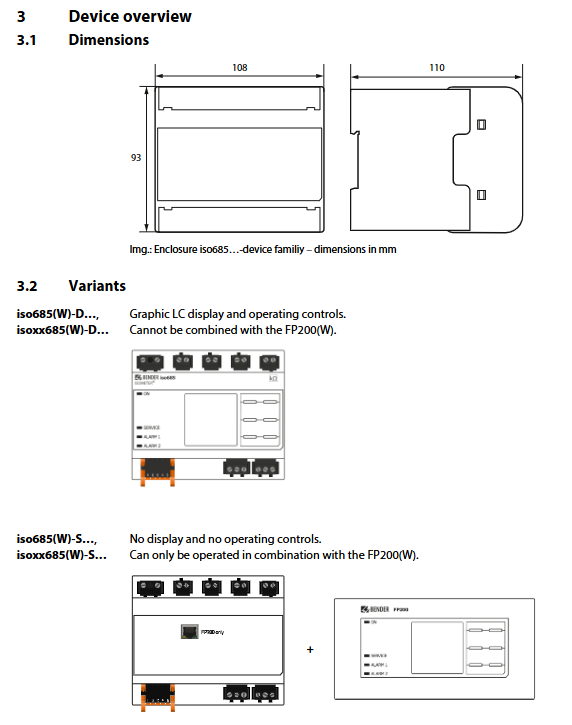
BENDER ISOMETER® iso685(W)-D/-S Insulation Monitoring Device
Convenient operation: Parameter setting, alarm reset, and self detection can be achieved through buttons such as MENU/TEST/RESET, and support remote parameter modification on web servers (with write permission enabled).
Model specifications and ordering information
(1) Core model parameters
Model Equipment Type Power Supply Voltage Protection Enhancement (Option W) Product Number
Iso685-D with display/button AC/DC 24~240 V No B91067010
Iso685W-D with display/button AC/DC 24~240 V (-40~+70 ℃, anti vibration) B91067010W
Iso685-S+FP200 no display+panel AC/DC 24~240 V No B91067210
Iso685W-S+FP200W without display+panel AC/DC 24~240 V is B91067210W
(2) Key components and coupling equipment
Basic accessories:
Mechanical accessories (terminal cover+mounting clip): B91067903
Screw Terminal Kit: B91067901
Push in terminal kit: B91067902
Front panel (FP200/FP200W): B91067904/B91067904W
Coupling equipment (extended voltage range):
Coupling device model applicable system voltage product number
AGH150W-4 3(N)AC 0~1150 V、DC 0~1760 V B98018006
AGH520S AC/3(N)AC 0~7200 V B913055
AGH204S-4 AC 0~1650 V (with rectifier 0~1300 V) B914013
AGH676S-4 AC 12 kV B913055
Key technical parameters
(1) Power supply and environmental parameters
Project Standard Version W Enhanced Version
Supply voltage range AC/DC 24~240 V (± 30%/± 15% tolerance) same as standard version
Power consumption ≤ 12 W (DC), ≤ 21 VA (AC 50/60 Hz) Same as standard version
Working temperature -25~+55 ℃ -40~+70 ℃ (UL application -40~+65 ℃)
Storage/transportation temperature -40~+70 ℃/-40~+85 ℃ Same as standard version
Protection level: internal IP30, terminal IP20, same standard version
Shell dimensions (width x height x depth) 108 mm x 93 mm x 110 mm as per standard version
Weight<390 g, same as standard version
(2) Measurement system parameters
Measurement parameter range accuracy
Insulation resistance 0.1 k Ω~20 M Ω± 15% (minimum ± 1 k Ω)
AC system voltage 0~690 V (RMS) ± 5% (minimum ± 5 V)
DC system voltage 0~1000 V ± 5% (minimum ± 5 V)
System frequency 0.1~460 Hz ± 1% (minimum ± 0.1 Hz)
Leakage capacitance 0~1000 μ F ± 10% (minimum ± 10 μ F)
DC offset voltage 20 V~1 kV-
Working principle and debugging process
(1) Basic workflow
After the device is connected to the power supply, it automatically starts self detection (15-20 seconds) to detect the internal circuit, measurement circuit, and grounding connection.
After passing the self-test, enter the normal monitoring mode and continuously collect parameters such as system insulation resistance and leakage capacitance.
When the insulation resistance is lower than the set response value, the response delay is activated (can be set to 0-300 seconds), and the corresponding alarm relay and LED indicator are triggered after the delay is over.
After troubleshooting, the parameters are restored to the release value (response value+25% hysteresis), the release delay is initiated, and the relay is reset after completion; When the fault memory is activated, the RESET button needs to be manually pressed to reset.
(2) Debugging process
Initial debugging: Connect the device → Connect the power supply → Run the debugging wizard (set language, date and time, system type, measurement profile, alarm response value) → Perform functional testing (simulate faults through grounding resistance).
Password configuration: Set a 4-digit password in the device menu, and verify it before modifying parameters.
Remote configuration: remotely read measurement values and modify parameters (with write permission enabled) through a web server (input device IP) or Modbus RTU protocol.
Typical application scenarios
Industrial power system: Monitor the insulation status of generators, frequency converters, and transformers to prevent equipment failures caused by insulation degradation.
Emergency power supply system: Insulation monitoring of backup power sources such as UPS and diesel generators to ensure the safety of power supply in emergency situations.
High capacitance scenario: For large leakage capacitance systems such as ships and rail transit, monitoring accuracy is optimized through "high capacitance" measurement profiles.
Low voltage control system: Insulation protection for industrial automation control circuits to prevent damage to sensitive components due to insulation faults.
Medium and high voltage expansion: Equipped with AGH series coupling equipment, monitor the insulation status of medium and high voltage IT systems such as 6 kV and 12 kV.
- OMRON
- ABB
- General Electric
- EMERSON
- Honeywell
- HIMA
- ALSTOM
- Rolls-Royce
- MOTOROLA
- Rockwell
- Siemens
- Woodward
- YOKOGAWA
- FOXBORO
- KOLLMORGEN
- MOOG
- KB
- YAMAHA
- BENDER
- TEKTRONIX
- Westinghouse
- AMAT
- AB
- XYCOM
- Yaskawa
- B&R
- Schneider
- KONGSBERG
- NI
- WATLOW
- ProSoft
- SEW
- ADVANCED
- Reliance
- TRICONEX
- METSO
- MAN
- Advantest
- STUDER
- DANAHER MOTION
- Bently
- Galil
- EATON
- MOLEX
- DEIF
- B&W
- ZYGO
- Aerotech
- DANFOSS
- Beijer
- Moxa
- Rexroth
- Johnson
- WAGO
- TOSHIBA
- BMCM
- SMC
- HITACHI
- HIRSCHMANN
- Application field
- XP POWER
- CTI
- TRICON
- STOBER
- Thinklogical
- Horner Automation
- Meggitt
- Fanuc
- Baldor
- SHINKAWA
- Other Brands
- UniOP
- KUKA
- Iba
- Beckhoff
-
 Basler D90 96801 100 PCB Card
 -
 Basler XR2002F Voltage Regulator (110 VAC, 48-480 Hz)
 -
 Basler SR8A-2B14B3A Regulator
 -
 Basler 9561500100 Module
 -
 Basler DECS-400 BE1-11 System
 -
 Basler DECS-100-B15 Excitation Control
 -
 Basler SCP 210 Frequency Controller
 -
 Basler SR4A-2B15B3A Static Voltage Regulator
 -
 Basler BE1-32R Power Relay
 -
 Basler PIA2400-17GM Power Interface Adapter
 -
 Basler MVC 232 Manual Voltage Control Module
 -
 Basler SSR 32-12 Static Voltage Regulator
 -
 Basler 5MW AVR Generator Voltage Regulator
 -
 Basler VR63-4B Voltage Regulator
 -
 Basler DECS-100-A05 AVR for Engine Generator
 -
 Basler DECS-100-B15 Automatic Voltage Regulator
 -
 Basler BE1-32R Directional Power Relay
 -
 Basler BE1-87B Differential Relay
 -
 Basler UFOV 260A Protective Module
 -
 Basler 9-2614-02-100 PCB Rev M
 -
Basler DECS-100-B15 Digital AVR
-
 Basler 9284900103 PS DECS-400N
 -
 Basler D4N3H1U Intertie Protection
 -
 Basler DECS-100-B15 A15 AVR
 -
 Basler KR4F Voltage Regulator
 -
 Basler BE26434 T14 Transformer
 -
 Basler SR8A-2B15B3A Regulator
 -
 Westinghouse 774B472A12 AR Relay
 -
Basler DECS-100-B15 AVR
-
Basler XR2002F Regulator 110V
-
Basler SR125-E Static Regulator
-
 Basler SSR 125-12 Regulator
 -
 Basler MOC2599 Motor Pot
 -
 Basler BE1-DFPR Feeder Relay
 -
 Basler CBS 305 Current Boost
 -
 Basler BE1-25 AutoSync
 -
 Basler MVC 300 Voltage Control
 -
 Basler BE3-25A AutoSync
 -
 Basler KR7FF Static Regulator
 -
 Basler 90-49000-100 Regulator
 -
 Basler 880 kVA Dry Type Transformer Specs
 -
 Basler Electric BE1-25 Sync-Check Relay Specs
 -
 Basler SSR 125-12 Voltage Regulator Specs
 -
 Basler Electric BE1-851 Overcurrent Relay Review
 -
Basler Electric 149D930G02 Control Sub-Assembly
-
 Basler Electric BE1-81O/UT Frequency Relay Specs
 -
 Basler Electric BE1-51/27C Overcurrent Relay
 -
 Basler Electric 149D956G02 Industrial Component
 -
Basler Electric BE1-51A Overcurrent Relay Specs
-
 Basler Electric BE1-40Q Loss of Excitation Relay
 -
 Basler DECS-200 Excitation Control System
 -
 Basler DECS-200 Voltage Regulator 56-277V AC / 125V DC
 -
Basler BE1-87T Transformer Differential Relay
-
 Basler RDP-110-S1 Protection Relay
 -
 Basler BE1-700V Digital Protective Relay
 -
 Basler BE1-951 Overcurrent Protection System
 -
 Basler DECS-300 Digital Excitation Control
 -
 Basler DECS-200 Digital Excitation Control
 -
 Basler DECS-200-1C Excitation Control System
 -
Basler DECS-200-1L Digital Excitation Control
-
 Basler Electric BE1-GPS Generator Protection System
 -
Basler Electric DECS-200-1C Digital Excitation Controller
-
 Basler Electric DECS125-15 Excitation Control with Power Module
 -
 Basler Electric BE1-87G Differential Relay
 -
 Basler Electric BE1-11 Protection System I5A3M2P2N0EA00
 -
Basler Electric DECS-200-1C Excitation Control System
-
Basler Electric BE1-11g Generator Protection Relay
-
Basler Electric DECS 125-15-B2C1 V2.0.9 Excitation Control
-
 Basler Electric BE1-81O/UT3ED1JA7N2F Frequency Relay
 -
Basler Electric BE1-81O/UT3EE1YB7N1F Frequency Relay
-
 Basler Electric DECS-200-1L Digital Excitation Control System
 -
Basler DECS125-15-B2C1 Excitation Control
-
 Basler 9507900205 SSR Retrofit Voltage Regulator
 -
 Basler BE2000E Digital Voltage Regulator
 -
 Basler BE1-GPS Generator Protection System
 -
Basler DECS-250-CN1CN1N Digital Excitation Control
-
 Basler DGC-2020 Genset Controller
 -
 Basler BE1-81O UT3ED1LA7N0F Frequency Relay (Variant)
 -
 Basler BE1-81O UT3EE1YA9S0F Frequency Relay (Variant)
 -
Basler BE1-81O Over/Under Frequency Relay
-
Basler DECS125-15 Digital Excitation Control
-
Basler Electric BE1-951 Overcurrent Protection System
-
 Basler Electric BE1-700V Digital Protective Relay
 -
 Basler Electric APR63-5 Automatic Voltage Regulator
 -
Basler Electric BE1-851 Overcurrent Protection System
-
Basler Electric DECS-250-LN1SN1N Excitation Control
-
 Basler Electric BE1-87T Transformer Differential Relay
 -
Basler Electric DECS-200-1L Excitation Control System
-
 Basler Electric 9310300100 DECS-300 Excitation Control
 -
 Basler Electric SSE-N 125-4.5KW Shunt Exciter Regulator
 -
 Basler Electric DGC-2020HD-5NS1DNSBA Genset Controller
 -
Basler Electric BE1-81-O/UT3EE1JB7N1F Frequency Relay
-
Basler Electric BE1-81T1EE1WA0N1F Frequency Relay
-
 Basler Electric BE1-25M1EA6PN5R1F Sync-Check Relay
 -
 Basler Electric BE1-GPS Generator Protection System
 -
Basler Electric DECS-250-LN1SN1N Excitation Control Rev V
-
 Basler Electric DECS-250-CN2CN1N Excitation Control
 -
Basler Electric BE1-50/51B-207 Overcurrent Relay
-
Basler Electric DECS-300-C0N0 Excitation Control System
-
Basler Electric DECS-200 Digital Excitation Control System
-
Basler Electric DECS-250-LN1CN1N Excitation Unit
-
Basler Electric DECS-250 LN2SA1D Excitation Unit Specs
-
Basler Electric BE1-87T Transformer Relay Review
-
Basler Electric BE1-11 Protection System
-
Basler Electric BE1-GPS100-E4N1H1N Protection System
-
 Allen-Bradley 442G-MABH-R Safety Module
 -
 Beckhoff CX1030-0111 PLC Assembly Profile
 -
 FANUC IC693CPU364 PLC Module
 -
 Orange Denmark Type 200816 220 PLC Specs
 -
 OMRON C200H-SNT31 Sysmac PLC Module
 -
 Allen Bradley 20AB022A3AYNANC0 PowerFlex 70
 -
 OMRON C200HW-PCU01 Position Control Unit
 -
 ABB AO845A-eA Analog Output Module
 -
 OMRON CJ1M-CPU22 CPU Unit
 -
 Allen Bradley 100-E265ED11 Contactor
 -
 Honeywell 51304511-100 Interface Module
 -
 SOLEXY BXF3S0101N0018 Gateway Module
 -
 OMRON CJ2H-CPU65 CPU Unit
 -
 Automation Direct GS2-45P0 AC Drive
 -
 M68-2000 2-Axis Motion CNC Controller
 -
 OMRON CJ1M-CPU11 V3.0 PLC CPU Unit
 -
 OMRON CJ1W-NC413 4-Axis Positioning Controller
 -
 OMRON 3G2A3-PRO16 Programming Console HMI
 -
 Siemens 3VT8440-2AA04-2GA2 Molded Case Circuit Breaker
 -
 Siemens 3RT5045 Contactor Series
 -
 OMRON C200HS-CPU01-E SYSMAC PLC Controller
 -
 OMRON C500-NC103-E Positioning Control Unit
 -
 OMRON CJ1W-TC001 Temperature Control Unit


