
YASKAWA 1000 series frequency converter
YASKAWA 1000 series frequency converter
Core Overview
This document is the Spanish technical manual (manual number TOSP C710606 22B) for the Yaskawa V1000 series vector controlled compact frequency converter (model CIMR-VU), covering 200V single/three-phase (0.1-18.5kW) and 400V three-phase (0.2-18.5kW) models. The core provides guidance around the entire life cycle of the equipment, including receiving inspection, mechanical/electrical installation, programming start-up, troubleshooting, regular maintenance, peripheral equipment adaptation and other key contents. It emphasizes safe operation norms and precise parameter configuration, supports the control of ordinary induction motors and permanent magnet synchronous motors (PM), and provides comprehensive technical support for installation, commissioning, daily operation and maintenance, and fault resolution in industrial scenarios.
Detailed analysis of core chapters
Basic Information and Security Principles of Documents
Basic Information
Product positioning: Vector controlled compact frequency converter, suitable for 7 typical industrial applications such as pumps, conveyors, fans, compressors, cranes, etc.
Voltage and power range: 200V single-phase (0.1-5.5kW), 200V three-phase (0.1-18.5kW), 400V three-phase (0.2-18.5kW).
Document purpose: To guide users in correctly installing, operating, and maintaining equipment, and to clarify that users need to pass on the manual to the end user.
Copyright Notice: All rights reserved by Yaskawa Electric in 2008. Reproduction and dissemination are prohibited without written permission. Product information may change with upgrades, and we do not assume any responsibility for losses caused by misuse of information.
General Safety Principles
Security level definition: divided into four levels: "PELIGRO (fatal danger)", "ADVERTENCIA (serious danger)", "PRECAUCI Ó N (minor injury)", "AVISO (property damage)", clarifying the warning requirements for different risk scenarios.
Core safety regulations: After power failure, wait for ≥ 5 minutes for capacitor discharge (bus voltage<50Vdc); Prohibit live wiring or touching circuit boards; Only qualified personnel are allowed to operate; The equipment needs to be fixed on a non flammable material surface; Avoid using incompatible voltage power sources.
Special warning: When connecting the motor to the frequency converter, it is forbidden to plug or unplug it with power on; Prohibit conducting voltage withstand tests on frequency converters; Follow the electrostatic discharge (ESD) process; Single phase motors cannot be used in conjunction with this frequency converter.
Reception and Inspection
Core Inspection Process
Appearance and damage inspection: After receiving, confirm that the equipment is not damaged during transportation. If there is any damage, immediately contact the transportation party.
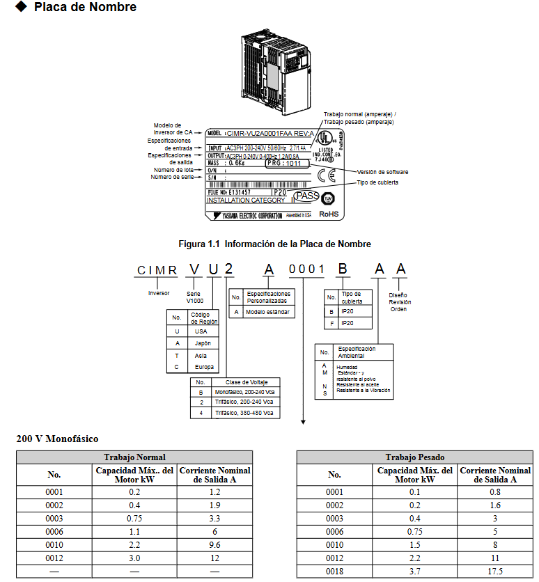
Model and nameplate verification: Confirm the model, input/output specifications, serial number and order consistency through the nameplate. The nameplate includes key information such as working mode (normal/heavy load), voltage level, output current, etc.
Model and protection type: The frequency converter provides two types of protection: IP20/open type (to be installed in a closed panel) and IP20/NEMA1 type (wall mounted), which need to be selected according to the installation scenario.
Component Identification
The key components include LED operators, heat sinks, terminal blocks, cooling fans, communication ports, etc. The layout of components with different protection types and power levels varies, and needs to be confirmed by referring to the manual illustrations.
Mechanical Installation
Installation environment requirements
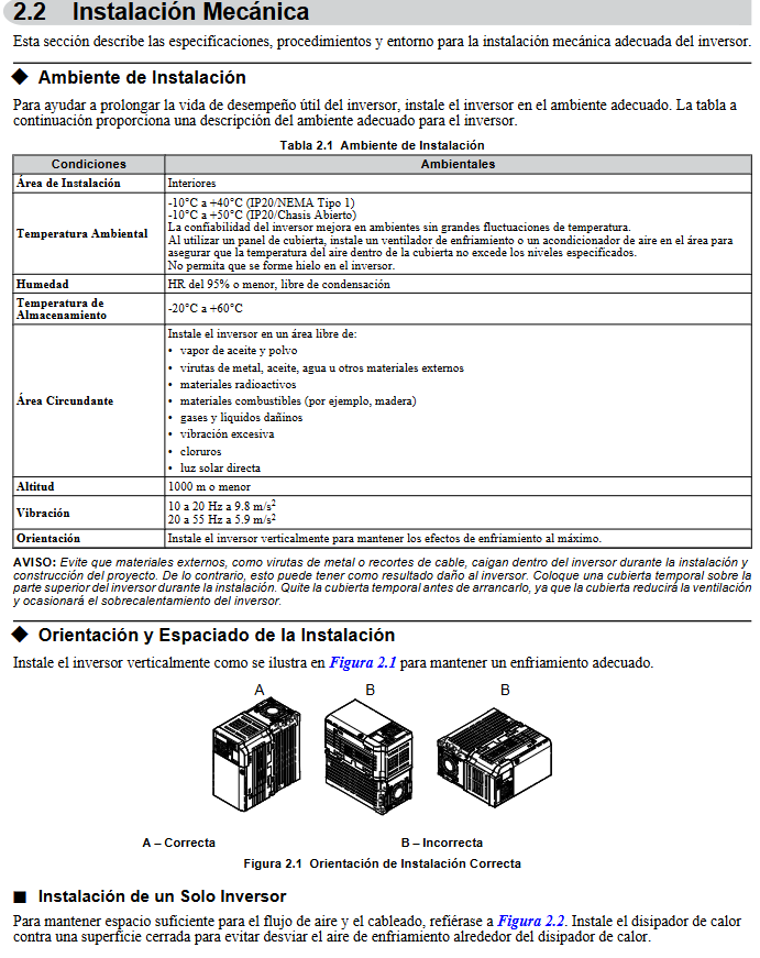
Environmental conditions: Indoor installation, temperature range IP20 open type (-10~50 ℃), IP20/NEMA1 type (-10~40 ℃), humidity ≤ 95%, no condensation, altitude ≤ 1000m, no dust, oil pollution, strong vibration (10-20Hz ≤ 9.8m/s ², 20-55Hz ≤ 5.9m/s ²).
Taboo environment: Avoid direct sunlight, corrosive gases, radioactive substances, and installation near flammable materials.
Installation specifications
Installation direction: It must be installed vertically to ensure heat dissipation effect, and horizontal or inclined installation is prohibited.
Spacing requirements: The vertical spacing of a single device should be ≥ 100mm, and the horizontal spacing should be ≥ 30mm; when multiple devices are installed side by side, the adjacent spacing should be ≥ 2mm, and the rated power should be reduced and the parameter L8-35 adjusted.
Size and fixing: The external dimensions and installation holes of different models of frequency converters vary, and the appropriate installation method should be selected according to the manual table. The fixing torque should meet the requirements (such as 0.5-0.6N · m for M3 bolts).
Electrical Installation
Wiring Safety and Standards
Wiring prerequisite: Power off and wait for the capacitor to discharge completely, wear insulation protective equipment to avoid cable cross interference.
Main circuit wiring: Use 600V ethylene insulated cables, and connect the main circuit terminals (R/L1, S/L2, T/L3, U/T1, V/T2, W/T3, etc.) according to the diagram. The grounding requirements are 200V level ≤ 100 Ω and 400V level ≤ 10 Ω.
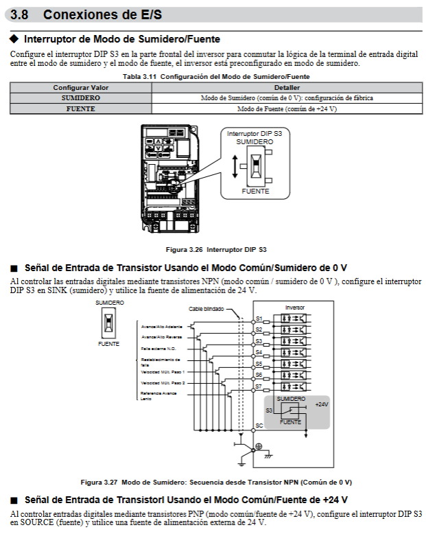
Control circuit wiring: Use shielded twisted pair cables to avoid parallel connection with the main circuit cables, and the shielding layer needs to be grounded; The control circuit terminals include digital input/output, analog input/output, communication terminals, etc., which need to be wired according to functional configuration.
Key Wiring Details
Braking resistor connection: can only be connected to B1/B2 terminals, and needs to be protected by a thermal relay to avoid overload and burnout.
Communication wiring: Supports MEMOBU/Modbus communication, requires the use of RS-485/422 cables, and the terminal resistance is controlled through DIP switch S2 (the end device needs to be turned on).
Cable specifications: Select the appropriate cable cross-sectional area based on the frequency converter model (such as 2mm ² recommended for the main circuit cable of the 200V single-phase 0.1kW model). After wiring, tighten the terminals with the required torque (such as 0.8-1.0N · m for M3.5 bolts).
Programming and Startup Operations
Use of LED Operators
Operator functions: including data display area, ESC key, RESET key, RUN key, up and down arrow keys, STOP key, ENTER key, LO/RE switch key, which can realize mode switching, parameter editing, operation monitoring, fault reset and other operations.
Display and indicator lights: RUN indicator light displays the running status, LO/RE indicator light displays the local/remote mode, ALM indicator light displays the fault status, and frequency, current, parameter and other information can be viewed through the digital display area.
Core Programming Settings
Control mode selection: Set through parameter A1-02, supporting V/f control (0), open-loop vector control (2), and open-loop vector control of permanent magnet synchronous motor (5).
Application preset parameters: Select 7 types of application presets (pumps, conveyors, etc.) through parameter A1-06, automatically configure the optimal parameters, and simplify debugging.
Basic parameter configuration: including acceleration/deceleration time (C1-01~C1-11), carrier frequency (C6-02, 2-15kHz optional), motor parameters (E2-01~E2-12, configurable through automatic adjustment function), frequency command source (b1-01), etc.
Start up process
Initialization settings: Select control mode and application presets based on the application scenario, and initialize parameters (A1-03).
Auto Ajuste: divided into rotary type (motor rotation, adapted to open-loop vector control) and stationary type (motor non rotation, adapted to V/f control), used for automatically configuring motor parameters to ensure control accuracy.
Trial operation: No load test (to confirm motor steering, acceleration/deceleration stability) → Load test (to verify operating status and parameter effectiveness) → Jogging operation (FJOG/RJOG function, 6Hz low-speed test).
Troubleshooting
Fault classification and warning
Fault types: including hardware faults such as overcurrent (oC), overvoltage (ov), overload (oL1/oL2), overheating (oH), operational errors such as communication errors (CE), parameter errors (oPE), and adjustment errors during the Auto Ajuste process.
Warning method: When a fault occurs, the LED operator displays a fault code and the ALM indicator light remains on; The ALM indicator light flashes when there is a minor malfunction or alarm.
Common troubleshooting solutions
Overvoltage (ov): Extend deceleration time (C1-02, etc.), install braking resistors, enable overvoltage suppression function (L3-11=1), check input voltage spikes.
Overcurrent (oC): Check motor insulation and wiring, reduce load, extend acceleration time, lower carrier frequency, confirm motor type matches control mode.
Overload (oL1): Reduce load, extend acceleration/deceleration time, check motor rated current configuration (E2-01), confirm motor cooling system is normal.
Parameter Error (oPE): Verify the parameter configuration logic (such as matching carrier frequency and cable length), restore default parameters, and reconfigure.
Fault reset method
Manual reset: Reset by pressing the RESET button on the operator.
Automatic reset: Configure parameter L5-01 to set the number of automatic retries.
Power off reset: Disconnect the power supply for ≥ 5 minutes and then power it back on (applicable to serious faults).
Regular Maintenance and Overhaul
Maintenance cycle and projects
Daily inspection: clean appearance, running sound, heat dissipation, terminal fastening status.
Regular inspection: Check cable aging, cooling fan operation status, capacitor and IGBT status every 6 months to 1 year (monitored through U4-05/U4-07).
Maintenance cycle: When the service life of the cooling fan expires (U4-04 ≥ 90%), it needs to be replaced in a timely manner; Replace capacitors and IGBTs when they reach the maintenance threshold.
Maintenance of key components
Cooling fan: Regularly clean the dust on the fan blades, replace them when damaged or aged, and reset the parameter o4-03=0 after replacement.
Terminals and cables: Check the tightness of the wiring to avoid looseness and overheating; Replace aging cables in a timely manner to ensure insulation performance.
Inverter replacement: During replacement, parameter configuration can be transferred through a detachable terminal block to reduce the workload of reprogramming.
Peripheral Devices and Options
Peripheral Device Adaptation
Protective equipment: Molded Case Circuit Breakers (MCCBs), Residual Current Circuit Breakers, Thermal Relays (OL), etc. must be installed to comply with local electrical regulations.
Filtering and reactors: Input filters, EMC filters, and AC/DC reactors can be installed to reduce electromagnetic interference and improve input current waveforms.
Communication Options
Supports MEMOBU/Modbus communication protocols and can be adapted to more bus protocols by extending the communication card. Wiring must follow communication specifications and configure corresponding parameters (such as baud rate and address).
Technical Specifications and Parameter List
Core specifications
Output characteristics: Voltage range 0- input voltage, frequency range 0-400Hz, overload capacity of normal working mode 120%/60s, overload mode 150%/60s.
Protection function: including multiple protections such as overcurrent, overvoltage, overload, overheating, phase loss, and ground fault.
Parameter List
Parameter grouping: divided into initialization parameters (A), application parameters (b), adjustment parameters (C), motor parameters (E), terminal function parameters (H), protection function parameters (L), monitoring parameters (U), etc., covering all configurable items such as control mode, operating parameters, protection thresholds, etc. Each parameter is labeled with default values, configuration ranges, and functional descriptions.
Key technical points
Motor adaptation
Supports ordinary induction motors and permanent magnet synchronous motors (PM). Permanent magnet synchronous motors require motor code (E5-01) and related parameters (E5-02~E5-24) to be configured, and speed search function (b3-01=1) to be enabled.
Motor parameter configuration: Accurate input of motor rated current, number of poles, rated power, and other information is required, or automatically obtained through the Auto Ajuste function to ensure control accuracy.
Differences in Control Modes
V/f control: Suitable for ordinary speed regulation scenarios (such as fans and pumps), with a simple structure and support for multi motor control.
Open loop vector control: suitable for high-precision speed regulation and high starting torque scenarios (such as conveyors and cranes), requiring Auto Ajuste to optimize parameters.
Permanent magnet synchronous motor control: efficient and energy-saving, suitable for scenarios with variable torque and high energy efficiency requirements, requiring dedicated parameter configuration.
Core taboos for safe operation
Prohibited items: live wiring/plugging of components, use of single-phase motors, covering of heat dissipation ports, modification of internal circuits of frequency converters, use of mismatched voltage power supplies.
Required items: reliable grounding, operation after power outage and discharge, operation by qualified personnel, tightening terminals according to specifications, regular maintenance of cooling system.
- OMRON
- ABB
- General Electric
- EMERSON
- Honeywell
- HIMA
- ALSTOM
- Rolls-Royce
- MOTOROLA
- Rockwell
- Siemens
- Woodward
- YOKOGAWA
- FOXBORO
- KOLLMORGEN
- MOOG
- KB
- YAMAHA
- BENDER
- TEKTRONIX
- Westinghouse
- AMAT
- AB
- XYCOM
- Yaskawa
- B&R
- Schneider
- KONGSBERG
- NI
- WATLOW
- ProSoft
- SEW
- ADVANCED
- Reliance
- TRICONEX
- METSO
- MAN
- Advantest
- STUDER
- DANAHER MOTION
- Bently
- Galil
- EATON
- MOLEX
- DEIF
- B&W
- ZYGO
- Aerotech
- DANFOSS
- Beijer
- Moxa
- Rexroth
- Johnson
- WAGO
- TOSHIBA
- BMCM
- SMC
- HITACHI
- HIRSCHMANN
- Application field
- XP POWER
- CTI
- TRICON
- STOBER
- Thinklogical
- Horner Automation
- Meggitt
- Fanuc
- Baldor
- SHINKAWA
- Other Brands
- UniOP
- KUKA
- Iba
- Beckhoff
-
 Basler DECS-200-2L Digital Excitation Control
 -
 Basler BE1-47N Voltage Phase Sequence Relay
 -
 Basler AEC63-7 Analog Excitation Controller 220-277V
 -
 Basler BE1-50/51B-107 Overcurrent Relay
 -
 Basler Electric BE1‑32R BE1‑E1P‑BON0F Protective Relay
 -
 Basler BE1-25 Solid State Time Overcurrent Relay M1EA6PA5S1F
 -
 Basler MVC 232 Manual Voltage Control Module 90 37000 103 60VAC 55VDC
 -
 Basler RAL6144-16GM Racer GigE Line Scan Camera
 -
 Basler SSR 63-12 Static Voltage Regulator
 -
 Basler BE1-51A Overcurrent Relay
 -
 Basler BE1-87T Solid State Protective Relay
 -
 Basler SR4A2B01B3A Static Voltage Regulator
 -
 Basler SSR 32-12 Static Voltage Regulator
 -
 Basler TRR00696 Transformer 1KVA 115V
 -
 Basler DECS-100-B15 AVR Replacement
 -
Basler BE1-27 Under-Voltage Relay
-
 Basler ACA2000-50GM Interface Module
 -
 Basler AEC63-7 Analog Excitation Controller
 -
 Basler PRS 250 Veri-Sync Relay
 -
 Basler SR4A-2B15B3A Static Voltage Regulator
 -
Basler BE1-32R Power Relay
-
Basler SR8A-2B06B3E Static Voltage Regulator
-
Basler BE1-81 O/U Frequency Relay
-
 Basler BE1-51A-K2E-W6M-B1N0F Overcurrent Relay
 -
Basler BE1-851 Overcurrent Relay G3A1S1 – 48-125V AC/DC
-
 Basler BEI-51 Overcurrent Relay – NSN 5945-01-293-2363
 -
Basler Electric L301KC Protective Relay – L301KC
-
 Basler DECS-100-B15 Automatic Voltage Regulator – Generator AVR
 -
 Basler SR4A-2B15B3A Static Voltage Regulator – SR4A2B15B3A
 -
 Basler UF 312 Under Frequency Protective Module – 9094700100
 -
Basler Electric MVC 232 Manual Control Module – 60VAC 55VDC 20A
-
Basler PRS 250 Veri-Sync Relay – Generator Synchronizing Relay
-
 Basler DECS-100-A05 Digital Regulator Review
 -
 Basler AEM-2020 Analog Expansion Module Specs
 -
 Basler DECS-100-B15 Digital Excitation Specs
 -
Basler Electric 9125600106 Regulator Component
-
Basler BE1-51A-K1E-W6M-B1N0F Overcurrent Relay
-
 Basler MVC-301 MVC 300 Excitation Controller
 -
 Basler SSR 32-12 Static Voltage Regulator
 -
 Basler 9-2849-00-101 Control Module
 -
Basler BE1-51A Overcurrent Relay
-
 Basler BE1-51/27R Overcurrent Relay
 -
 Basler BE1-51 Overcurrent Relay
 -
 Basler SR8A-2B15B3A Static Voltage Regulator
 -
 Basler BE32965001 Transformer and Timer Board
 -
 Basler 9174700100 EL200-7 Excitation Limiter
 -
 Basler BE2000E AVR Voltage Regulator
 -
Basler BE1-87G Differential Relay
-
 Basler BE21834001 Generator Control Module
 -
Basler DECS-100-B15 AVR
-
 Basler D90 96801 100 PCB Card
 -
 Basler XR2002F Voltage Regulator (110 VAC, 48-480 Hz)
 -
 Basler SR8A-2B14B3A Regulator
 -
 Basler 9561500100 Module
 -
 Basler DECS-400 BE1-11 System
 -
 Basler DECS-100-B15 Excitation Control
 -
 Basler SCP 210 Frequency Controller
 -
Basler SR4A-2B15B3A Static Voltage Regulator
-
Basler BE1-32R Power Relay
-
 Basler PIA2400-17GM Power Interface Adapter
 -
 Basler MVC 232 Manual Voltage Control Module
 -
 Basler SSR 32-12 Static Voltage Regulator
 -
Basler 5MW AVR Generator Voltage Regulator
-
 Basler VR63-4B Voltage Regulator
 -
Basler DECS-100-A05 AVR for Engine Generator
-
Basler DECS-100-B15 Automatic Voltage Regulator
-
Basler BE1-32R Directional Power Relay
-
Basler BE1-87B Differential Relay
-
 Basler UFOV 260A Protective Module
 -
 Basler 9-2614-02-100 PCB Rev M
 -
Basler DECS-100-B15 Digital AVR
-
 Basler 9284900103 PS DECS-400N
 -
 Basler D4N3H1U Intertie Protection
 -
 Basler DECS-100-B15 A15 AVR
 -
 Basler KR4F Voltage Regulator
 -
 Basler BE26434 T14 Transformer
 -
 Basler SR8A-2B15B3A Regulator
 -
 Westinghouse 774B472A12 AR Relay
 -
Basler DECS-100-B15 AVR
-
Basler XR2002F Regulator 110V
-
Basler SR125-E Static Regulator
-
Basler SSR 125-12 Regulator
-
Basler MOC2599 Motor Pot
-
 Basler BE1-DFPR Feeder Relay
 -
 Basler CBS 305 Current Boost
 -
Basler BE1-25 AutoSync
-
Basler MVC 300 Voltage Control
-
 Basler BE3-25A AutoSync
 -
 Basler KR7FF Static Regulator
 -
Basler 90-49000-100 Regulator
-
 Basler 880 kVA Dry Type Transformer Specs
 -
Basler Electric BE1-25 Sync-Check Relay Specs
-
 Basler SSR 125-12 Voltage Regulator Specs
 -
 Basler Electric BE1-851 Overcurrent Relay Review
 -
Basler Electric 149D930G02 Control Sub-Assembly
-
 Basler Electric BE1-81O/UT Frequency Relay Specs
 -
 Basler Electric BE1-51/27C Overcurrent Relay
 -
 Basler Electric 149D956G02 Industrial Component
 -
Basler Electric BE1-51A Overcurrent Relay Specs
-
 Basler Electric BE1-40Q Loss of Excitation Relay
 -
Basler DECS-200 Excitation Control System
-
 Basler DECS-200 Voltage Regulator 56-277V AC / 125V DC
 -
Basler BE1-87T Transformer Differential Relay
-
 Basler RDP-110-S1 Protection Relay
 -
 Basler BE1-700V Digital Protective Relay
 -
 Basler BE1-951 Overcurrent Protection System
 -
 Basler DECS-300 Digital Excitation Control
 -
 Basler DECS-200 Digital Excitation Control
 -
 Basler DECS-200-1C Excitation Control System
 -
Basler DECS-200-1L Digital Excitation Control
-
 Basler Electric BE1-GPS Generator Protection System
 -
Basler Electric DECS-200-1C Digital Excitation Controller
-
 Basler Electric DECS125-15 Excitation Control with Power Module
 -
Basler Electric BE1-87G Differential Relay
-
 Basler Electric BE1-11 Protection System I5A3M2P2N0EA00
 -
Basler Electric DECS-200-1C Excitation Control System
-
Basler Electric BE1-11g Generator Protection Relay
-
Basler Electric DECS 125-15-B2C1 V2.0.9 Excitation Control
-
Basler Electric BE1-81O/UT3ED1JA7N2F Frequency Relay
-
Basler Electric BE1-81O/UT3EE1YB7N1F Frequency Relay
-
 Basler Electric DECS-200-1L Digital Excitation Control System
 -
Basler DECS125-15-B2C1 Excitation Control
-
 Basler 9507900205 SSR Retrofit Voltage Regulator
 -
 Basler BE2000E Digital Voltage Regulator
 -
 Basler BE1-GPS Generator Protection System
 -
Basler DECS-250-CN1CN1N Digital Excitation Control
-
 Basler DGC-2020 Genset Controller
 -
Basler BE1-81O UT3ED1LA7N0F Frequency Relay (Variant)


