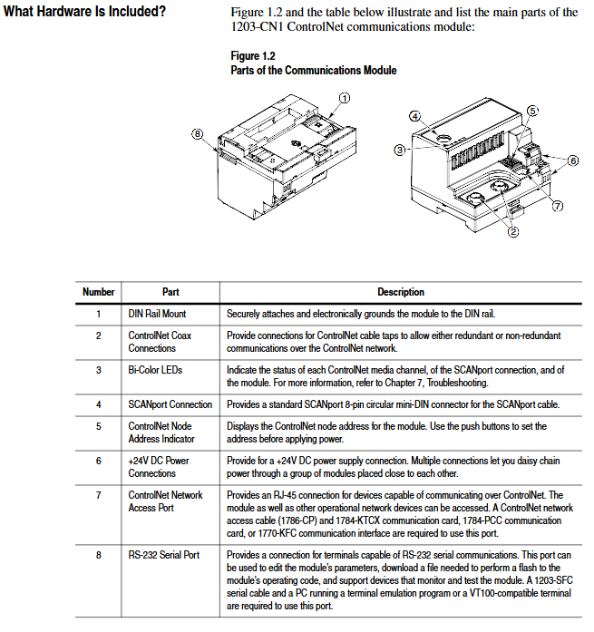
Allen Bradley 1203-CN1 ControlNet Communication Module
5-8 DataLnk A-D Config Enable/Disable corresponding data link (each channel occupies 2 inputs+2 output words) 0 (disabled)
9-10 Idle/Comm Flt Action PLC programming mode/action in case of network failure (0=fault, 1=zero data, 2=hold last value, 3=fault configuration value) 0 (fault)
11-20 Fault Cfg Logic/Ref/A1-D2 In: The preset values (logic instructions, reference values, data link values) outputted during a fault are 0
21 Serial Port Rate (0=2400, 1=4800, 2=9600, 3=19.2K, 4=38.4K) 2 (9600)
22 Reset Adapter Reset Module (1=Reset, 2=Reset after restoring default parameters) 0 (Ready)
2. Firmware Upgrade (Flash Upgrade)
Prepare the upgrade file (such as cn1-0_61.bin), connect via serial port to enter the main menu, and select "7>Update Flash Program".
Confirm that the SCANPort product is in a safe state (the product will malfunction and shut down during the upgrade), and press Y to start the upgrade.
Select "Send File" from the "Transfer" menu in the terminal software, choose Xmodem for the protocol, and select "Upgrade File Send". The entire process cannot be interrupted, and the module will automatically restart after completion.

ControlNet Network Configuration
1. Configuration tools and prerequisites
Software: RSNetWorx for ControlNet (32-bit Windows application), RSLinx (communication interface).
Hardware: The PC needs to be connected to the ControlNet network through a 1784-KTCX/1784-PCC card or 1770-KFC adapter.
2. Network configuration steps
Enter online mode: Start RSNetWorx, click "Online", automatically scan the network through RSLinx, and select the target ControlNet network.
Module Mapping:
Click on 'Edits Enabled', right-click on the controller (such as PLC-5) and select 'ControlNet Configuration'.
Select the node (module node address) corresponding to the SCANPort product, insert "Device Connection", and configure the unique N-file address for diagnostic/status/data input/output files.
Set input/output size (control I/O enable+2 words, each data link+2 words, range 2-10 words), RPI (request packet interval) ≥ network update time (NUT).
Save and Verify: Save the configuration file and download it to the controller. Set NUT ≥ 5ms, Max Scheduled Address ≥ highest I/O node address, and Max Unscheduled Address ≥ highest network node address in the network properties.
Configuration confirmation: The SCANPort product icon in RSNetWorx displays a gray flag, and the ControlNet LED of the controller and module is constantly green, indicating normal communication.
PLC programming and message communication
1. Ladder diagram programming (RSLogix5)
Implement I/O interaction between the controller and SCANPort product through N-file mapping. Example functions include start stop control, fault clearing, and frequency reference value transmission. Please note:
Logical instruction bit definition: For example, in the 1336 PLUS driver, bit 0=stop, bit 1=start, bit 2=jog, and bit 3=fault clearing. Please refer to the SCANPort product manual for details.
Data scaling: For example, the frequency reference value 0-32767 of the 1305 driver corresponds to 0-maximum frequency, which needs to be transmitted through MOV instructions in the program (such as N7:0 → N13:1).
2. Message communication (PCCC and analog block transmission)
(1) PCCC message
Support PLC-5 Typed Read/Write and encapsulate protocol messages, examples include:
Read 10 SCANPort product parameters (starting parameter 1): target address N10:1, PLC data storage N20:0, Size=10.
Read the complete information of a single parameter (such as parameter 1): target address N30:1, size=20 (including parameter name, unit, maximum value, etc.).
(2) Simulated Block Transfer
Supports 11 types of commands such as parameter read/write, fault queue query, NVS storage operation, etc., which need to be implemented through 2 MSG instructions (write request first, then read response). Examples include:
Parameter value reading: Request instruction length of 3 words (message length 3, decimal 769, parameter number), respond with parameter value or error code.
Fault queue reading: Request to specify queue number, respond with fault text (displayed in reverse ASCII), fault code, and timestamp (supported by 1336 FORCE).

Troubleshooting and LED diagnosis
1. Interpretation of LED status
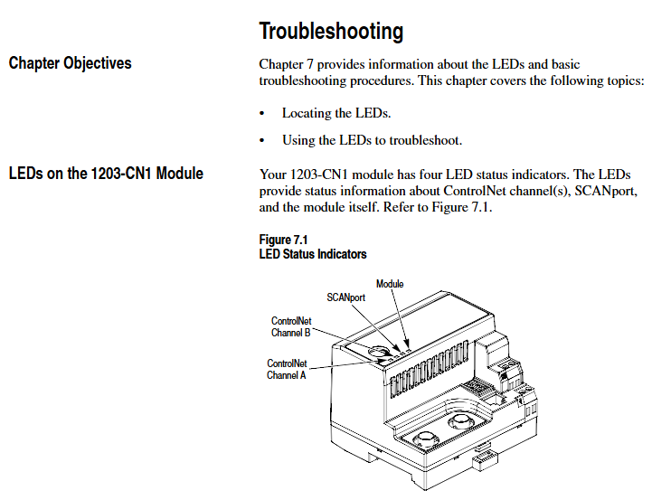
The colors and flashing patterns of the four LEDs in the module correspond to different states. The core troubleshooting is as follows:
Solution for LED type status reasons
Check the cable/tap for faults in the red link interface of both ControlNet A/B. Power off and restart, if ineffective, contact after-sales service
SCANPort flashing red SCANPort communication error/data link does not support reconnecting cables, verify module compatibility with product configuration
Module flashing red (3 times) Non volatile storage CRC error check parameters, modify and save at least 1 parameter, then restart
Module flashing green configured I/O but no ControlNet connection confirmed controller network configuration, remap module
2. Event queue and DF1 statistics
Event queue: Select "3>Display event queue" from the main menu to view fault/warning information (graded by severity: I=information, W=warning, S=serious, F=fatal), which can be cleared through "Clr Event Queue".
- ABB
- General Electric
- EMERSON
- Honeywell
- HIMA
- ALSTOM
- Rolls-Royce
- MOTOROLA
- Rockwell
- Siemens
- Woodward
- YOKOGAWA
- FOXBORO
- KOLLMORGEN
- MOOG
- KB
- YAMAHA
- BENDER
- TEKTRONIX
- Westinghouse
- AMAT
- AB
- XYCOM
- Yaskawa
- B&R
- Schneider
- Kongsberg
- NI
- WATLOW
- ProSoft
- SEW
- ADVANCED
- Reliance
- TRICONEX
- METSO
- MAN
- Advantest
- STUDER
- KONGSBERG
- DANAHER MOTION
- Bently
- Galil
- EATON
- MOLEX
- DEIF
- B&W
- ZYGO
- Aerotech
- DANFOSS
- Beijer
- Moxa
- Rexroth
- Johnson
- WAGO
- TOSHIBA
- BMCM
- SMC
- HITACHI
- HIRSCHMANN
- Application field
- XP POWER
- CTI
- TRICON
- STOBER
- Thinklogical
- Horner Automation
- Meggitt
- Fanuc
- Baldor
- SHINKAWA
- Other Brands


