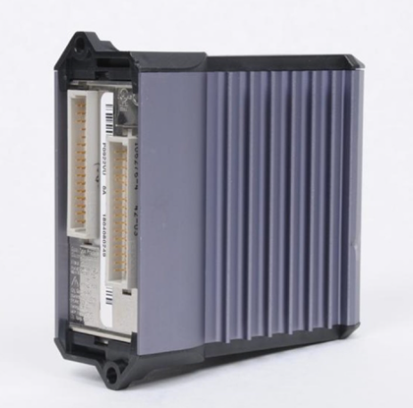
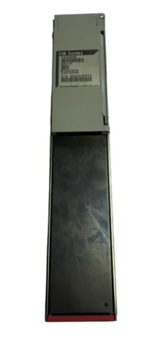
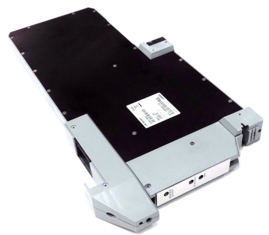
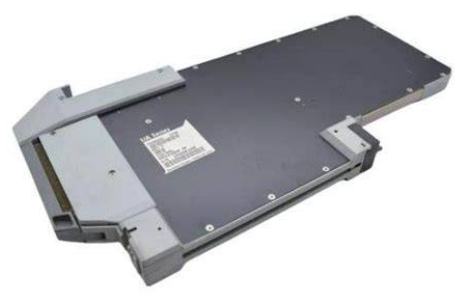
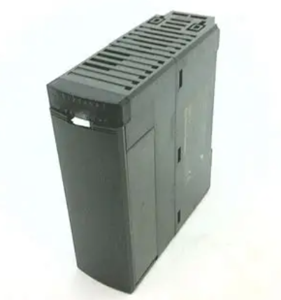
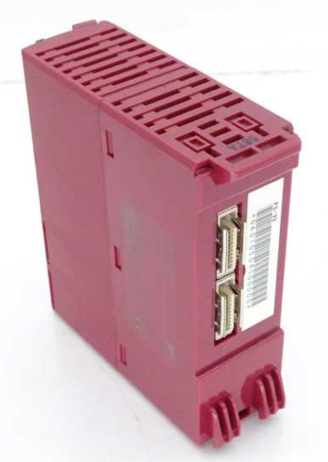
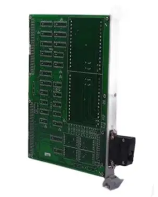
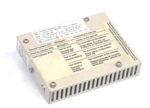
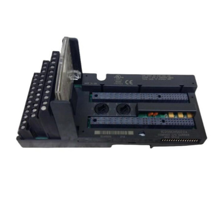
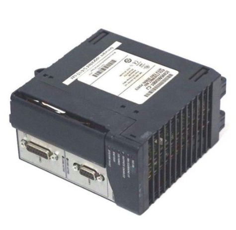
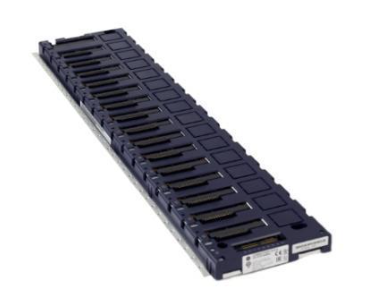
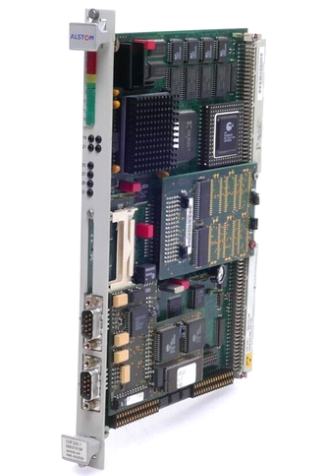
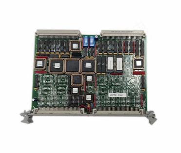
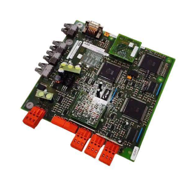
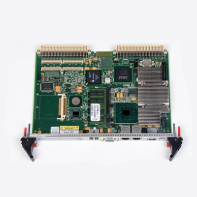
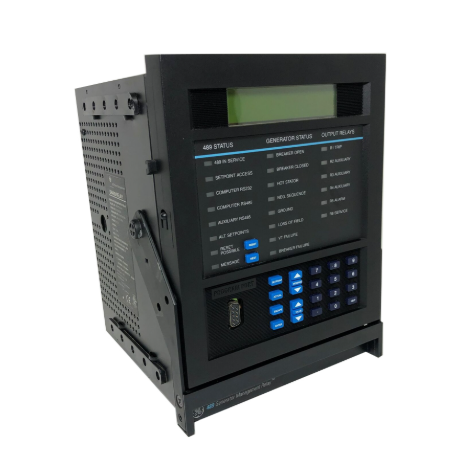
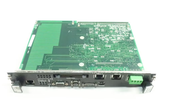
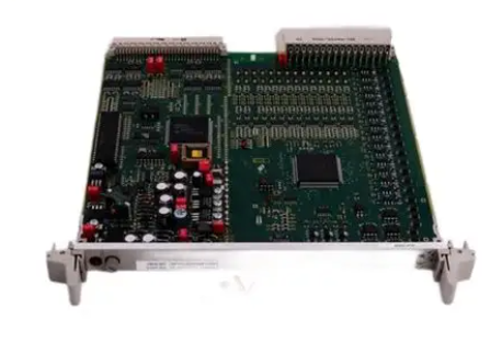
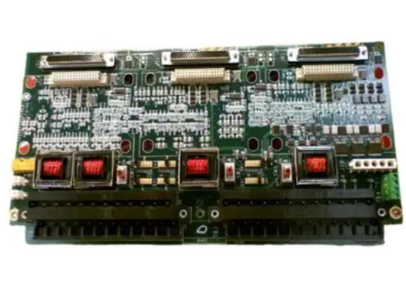
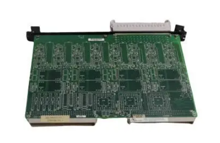
ControlLogix AutoMax DCSNet and AutoMax Remote I/O Communication Interface Module
Remote I/O Communication Interface Module

• sending an erroneous signal to your system’s actuators
causing unintended machine motion or loss of process
control.
• causing an explosion in a hazardous environment.Repeated electrical arcing causes excessive wear to contacts on both the module and its mating connector. Worn contacts may create electrical resistance that can affect module operation.
Wire the Connector for the AutoMax Network
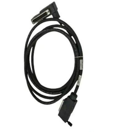
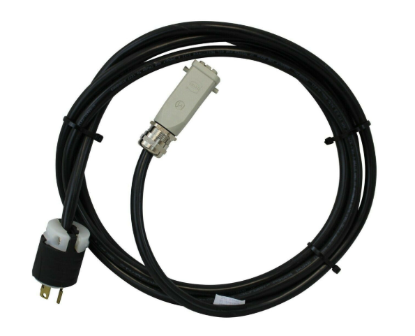
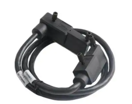
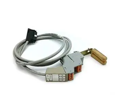
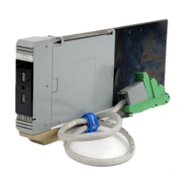
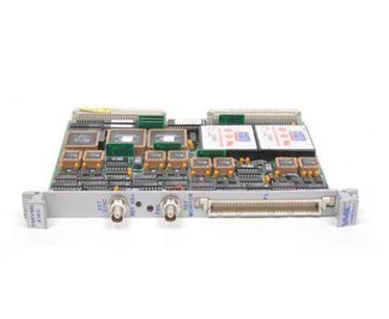
Use a drop cable, 612574-36R, available through Rockwell Automation Systems Business, and passive tap M/N 57C380 to connect the module to the coaxial network cable. This cable turns down and has a ferrite to reduce EMI. This cable must be used in CE applications. You can also use drop cable 612403-036R but it points up.
The drop cable is a 3-foot long multi-conductor cable with 9-pin D-shell connectors at each end. Connect one end to the connector on the module and the other end to the passive tap.
The passive tap has two BNC connectors for connection to the coaxial cables and terminating loads.
The network coaxial cable must be terminated with 75 ohm terminating loads attached to the taps at the physical ends of the network. There should be two and only two terminators on the network.
For DCS, the network cable can be RG-59/U or RG-11/U. For remote I/O, the cable must be RG-59/U.
Check Power Supply and Module Status
The rack power supply indicator should be green.
The module OK LED should be solid red, then solid green.
The alphanumeric display shows the following messages at powerup.
OK LED – Module Health
A bicolor OK LED indicates module health. A red LED indicates that module startup diagnostics have failed or a major module fault such as watchdog bite or jabber inhibit has occurred. Green indicates that the card has passed all power-up diagnostics and is functioning normally. This LED is red during powerup.
If all three LEDs are solid red and the 4-character display shows something like M#66, this indicates that a fatal error has occurred. Refer to the User Guide for information on clearing fatal errors.
Where to Find Information on Configuring Your 56AMXN/B Module
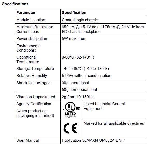
Now that you have installed your AutoMax DCS/RIO module, you must configure it. For this information, refer to the configuration chapters of your 56AMXN User’s Guide, publication 56AMXN-UM002A-EN-P.
This manual is supplied on the 56AMXN/B distribution CD. The CD also contains the Adobe PDF reader.
Hazardous Location information
The following information applies when operating this equipment in hazardous locations:
The 56AMXN is NOT suitable for use in hazardous locations.Products marked “CL I, DIV 2, GP A, B, C, D” are suitable for use in Class I Division 2 Groups A, B, C, D, Hazardous Locations and nonhazardous locations only. Each product is supplied with markings on the rating nameplate indicating the hazardous location temperature code. When combining products within a system,the most adverse temperature code (lowest “T” number) may be used to help determine the overall temperature code of the system. Combinations of equipment in your system are subject to investigation by the local Authority Having Jurisdiction
at the time of installation
- EMERSON
- Honeywell
- CTI
- Rolls-Royce
- General Electric
- Woodward
- Yaskawa
- xYCOM
- Motorola
- Siemens
- Rockwell
- ABB
- B&R
- HIMA
- Construction site
- electricity
- Automobile market
- PLC
- DCS
- Motor drivers
- VSD
- Implications
- cement
- CO2
- CEM
- methane
- Artificial intelligence
- Titanic
- Solar energy
- Hydrogen fuel cell
- Hydrogen and fuel cells
- Hydrogen and oxygen fuel cells
- tyre
- Chemical fiber
- dynamo
- corpuscle
- Pulp and paper
- printing
- fossil
- FANUC
- Food and beverage
- Life science
- Sewage treatment
- Personal care
- electricity
- boats
- infrastructure
- Automobile industry
- metallurgy
- Nuclear power generation
- Geothermal power generation
- Water and wastewater
- Infrastructure construction
- Mine hazard
- steel
- papermaking
- Natural gas industry
- Infrastructure construction
- Power and energy
- Rubber and plastic
- Renewable energy
- pharmacy
- mining
- Plastic industry
- Schneider
- Kongsberg
- NI
- Wind energy
- International petroleum
- International new energy network
- gas
- WATLOW
- ProSoft
- SEW
- wind
- ADVANCED
- Reliance
- YOKOGAWA
- TRICONEX
- FOXBORO
- METSO
- MAN
- Advantest
- ADVANCED
- ALSTOM
- Control Wave
- AB
- AMAT
- STUDER
- KONGSBERG
- MOTOROLA
- DANAHER MOTION
- Bently
- Galil
- EATON
- MOLEX
- Triconex
- DEIF
- B&W
- ZYGO
- Aerotech
- DANFOSS
- KOLLMORGEN
- Beijer
- Endress+Hauser
- MOOG
- KB
- Moxa
- Rexroth
- YAMAHA
- Johnson
- Westinghouse
- WAGO
- TOSHIBA
- TEKTRONIX


Email:wang@kongjiangauto.com

