
TOSHIBA 1600XPi Series UPS Installation and Operation
Applicable scenarios: General electronic applications (computers, personal devices, office equipment, measuring equipment, industrial robots, household appliances, etc.)
Prohibited scenarios (DANGER): medical operating room equipment, life support equipment, fire-fighting equipment; Special scenarios (such as nuclear power plants, communication equipment, transportation equipment) require consultation with professional technical personnel (Warning)
TOSHIBA 1600XPi Series UPS Installation and Operation
Product Scope and Application
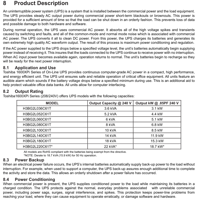
Product specifications: Single phase UPS, with a capacity coverage of 3.6/5.2/6/8/10/14/18/22 KVA, corresponding to output power (at 0.85 power factor) of 3.1/4.4/5.1/6.8/8.5/11.9/15.3/18.7 kW (22KVA is reduced to 18.7kVA at 50Hz)
Applicable scenarios: General electronic applications (computers, personal devices, office equipment, measuring equipment, industrial robots, household appliances, etc.)
Prohibited scenarios (DANGER): medical operating room equipment, life support equipment, fire-fighting equipment; Special scenarios (such as nuclear power plants, communication equipment, transportation equipment) require consultation with professional technical personnel (Warning)
Core Security Standards
Personnel qualification requirements
Only qualified personnel are allowed to install, operate, and maintain, and must meet the following requirements:
Read the complete manual to master the construction and operation of the equipment
Received safety training on circuit switching, grounding, locking and tagging (LOTO), etc
Master the usage of protective equipment (insulated gloves, safety helmets, etc.)
Having first aid skills and understanding of battery handling precautions
Safety symbols and signal words
Safety symbols: including safety warning (potential personal injury), prohibition (not operable), mandatory (must be executed), grounding (position of grounding conductor), electric shock (internal high voltage), explosion (components may explode), etc
Signal word grading:
DANGER: Immediate danger that may result in death/serious injury if not avoided (e.g. prohibited for use in life support equipment)
Warning: Potential danger, failure to avoid may result in death/serious injury (professional consultation is required for special situations)
CAUTION: Potential danger, may cause minor/moderate injury if not avoided (such as insulation tools required for battery operation)
NOTICE: Potential danger, may cause equipment/property damage if not avoided (if ventilation space is required for installation)
Key operation taboos
After power failure, wait for 5 minutes until the internal capacitor is completely discharged before opening the cover
Unauthorized modification of equipment (without written permission from Toshiba) is prohibited, otherwise all warranties will be invalidated and may result in UL/CHUL/CE/ETL certification being invalidated, causing personal injury or equipment damage
Batteries are prohibited from being baked or disassembled by fire (harmful electrolyte). Replacement must be carried out by authorized personnel from Toshiba, and the same type of battery pack must be used
Installation and wiring specifications
Installation environment requirements
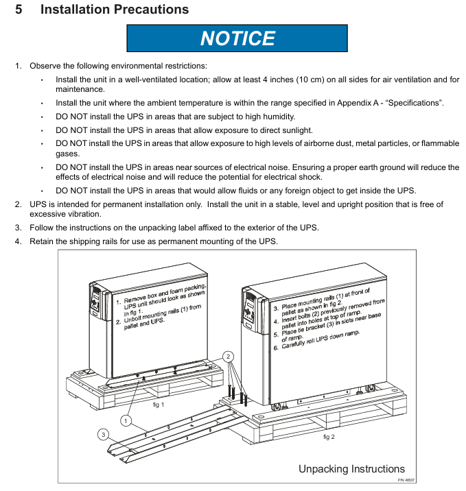
Ventilation: Install in a well ventilated area, leaving at least 4 inches (10cm) of space around for ventilation and maintenance
Temperature: Operating temperature 0-40 ℃ (60Hz), 0-33 ℃ (50Hz); Storage temperature -20-40 ℃, optimal storage temperature 21 ℃
Other: Avoid moisture (30-90% humidity without condensation), dust/metal particles, direct sunlight, electrical noise sources, liquid intrusion, and place horizontally (without excessive vibration)
Input/output protection configuration
The user needs to configure a circuit breaker between the UPS input (mains) and output (load), with specifications as shown in the table below:
240VAC specification 3.6 kVA 5.2/6 kVA 8 kVA 10 kVA 14 kVA 18 kVA 22 kVA
Input circuit breaker 30 A 50 A 60 A 70 A 100 A 100 A 125 A
Output circuit breaker 20 A 35 A 45 A 60 A 80 A 100 A 125 A
Note: The above specifications are for equipment with 80% rated value
Terminal wiring and cable requirements
Terminal block type:
Type 1: Input at 208/240V, output at 120/208/240V, to be tripped according to the input voltage (208V short circuited to terminals 11-12, 240V short circuited to terminals 12-13)
Type 2: 240V input, 100/200V output, 100V output connected to 4-6 or 6-7 terminals, 200V output connected to 4-7 terminals
Cable specifications: All input, output, and grounding wires require 90 ℃ copper wire. The cable size and torque are shown in the following table:
Project Terminal Number Cable Size (AWG) -3.6kVA Cable Size (AWG) -5.2-6kVA Cable Size (AWG) -8kVA Cable Size (AWG) -10kVA Cable Size (AWG) -14-18kVA Cable Size (AWG) -22kVA Tightening Torque (lb. - in./N · m)
AC input line 1、2 10(8) 8(8) 8(1/0) 6(1/0) 4(1/0) 1(1/0) 14.2(1.56)
AC output line 4、5、7 12(8) 10(8) 8(1/0) 6(1/0) 4(1/0) 1(1/0) 14.2(1.56)
AC output neutral line 6 12(8) 10(8) 8(1/0) 6(1/0) 4(1/0) 1(1/0) 14.2(1.56)
ground wire 3、8 12(8) 10(8) 8(1/0) 6(1/0) 4(1/0) 1(1/0) 14.2(1.56)
EPO switch 14, 15 16 16 16 16 16 16 9.0 (0.99)
Remote switch 16, 17 16 16 16 16 16 16 9.0 (0.99)
Note: The maximum cable size that the terminal can accommodate is indicated in parentheses
Operation process and operating mode
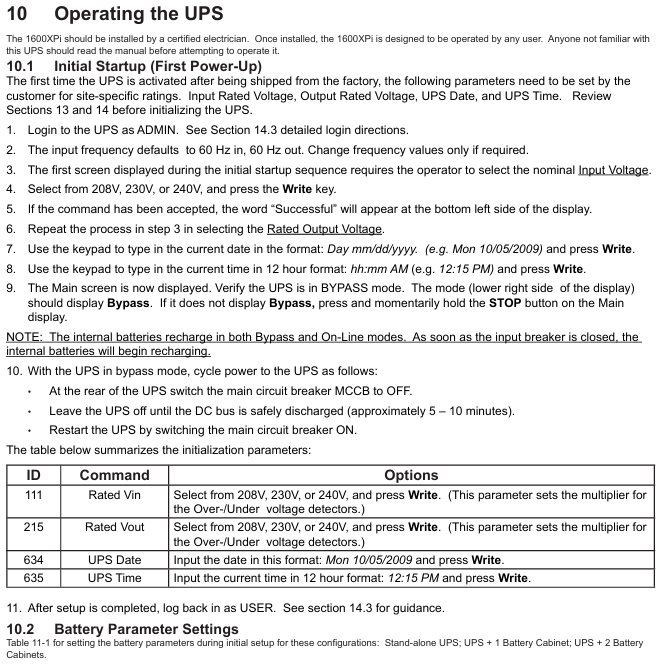
Initial Startup (First Power Up)
Login: Log in with ADMIN privileges (default password ADMIN)
Parameter settings:
Enter the rated voltage (208V/230V/240V) and confirm with Write
Output rated voltage (208V/230V/240V), confirm with Write
Set date (format: Day mm/dd/yyyy, such as Mon 10/05/2009)
Set time (in 12 hour format, such as 12:15 PM)
Charging: After initial startup, the battery needs to be charged for at least 24 hours (with the input circuit breaker open), otherwise the backup time will be shortened
Normal start and stop
Start: Open the rear main circuit breaker (MCCB) of the UPS and confirm that the "On Line" green light on the front panel is on; If it's not on, press the RUN button for 3 seconds (hear a beep sound)
Stop: Press the STOP button for 3 seconds (after a beep, the "On Line" light goes out and enters bypass mode); To completely stop, turn off the MCCB circuit breaker (all sensitive loads must be turned off first)
Core operating mode
Static Bypass mode: Automatically switches when UPS overload or internal failure occurs, with power directly supplied to the load through the bypass from the input, with a switching time of less than 1/4 cycle (no load interruption); After overload relief, it can automatically switch back (AutoXfer parameter needs to be enabled)
On Line mode: Normal operation mode, the input AC is converted to DC through a rectifier (including a boost chopper circuit), and the charging battery is simultaneously supplied to the inverter to generate high-quality sine wave AC output. The battery is always in a charging state
Battery Backup Mode: When the mains power is interrupted, the battery immediately supplies DC to the inverter and converts it to AC output; Backup time is 5-8 minutes (full load, depending on model), and the power supply will automatically stop when the battery voltage drops to the "shutdown voltage (Vmin)"
EPO mode (Emergency Power Off): remotely close the EPO switch (normally open), immediately cut off the UPS input circuit breaker, output, and battery circuit; After activation, wait for 5 minutes for discharge before maintenance
Battery management and maintenance
Key parameters of battery
Nominal voltage (Vnom): 3.6KVA is 144Vdc, 5.2-6KVA is 216Vdc, 8-22KVA is 288Vdc
Low voltage alarm (Vlow): 3.6KVA is 130Vdc, 5.2-6KVA is 192Vdc, 8-22KVA is 246Vdc
Shutdown voltage (Vmin): 3.6KVA is 114Vdc, 5.2-6KVA is 170Vdc, 8-22KVA is 227Vdc
Charging parameters: Charging is divided into three stages (constant current 1A → constant voltage → float charging), and it takes 24 hours to fully charge (12 hours for 90% charging)
Battery testing and storage
Test:
Automatic testing: Enable at startup, wait for the 'Battery Test Frequency (CMD 655)' time before re enabling after completion
Manual testing: In UPS online mode, log in with ADMIN privileges, set CMD 652=Disable, CMD 653=Enable, and CMD 655=0, and press the "BattTest" button on CMD 609; Test failed with 'BTSTFL' warning displayed
Storage:
Before storage: Start up and run without load for 24 hours to fully charge the battery, stop UPS and turn off MCCB
Storage conditions: Original packaging, wooden/metal tray, temperature -20-40 ℃, avoid humidity/dust/vibration
Maintenance: Charge every 9 months for temperatures below 20 ℃, every 6 months for temperatures between 20-30 ℃, and every 3 months for temperatures between 30-40 ℃
Preventive maintenance and component replacement
Daily maintenance: Keep the ventilation openings clean and regularly remove dust (using a vacuum cleaner for dusty environments)
Component replacement cycle:
Aluminum electrolytic capacitor: every 7 years
Fuse: Every 7 years
Cooling fan: Every 3.5 years for environments between 30-40 ℃, and every 5 years for environments below 30 ℃ (non hot swappable, needs to be replaced after disconnecting and discharging)
Battery: Depending on the ambient temperature, 20-25 ℃ is 5 years, 30 ℃ is 3.5 years, 35 ℃ is 2.5 years, 40 ℃ is 1.8 years, and 45 ℃ is 1.25 years (requiring overall replacement, using the same model of battery pack)
Fault Handling and Technical Appendix
Fault and warning codes
Fault code (partially critical):
BYPOH: Bypass overheating, check the fan/ambient temperature (>40 ℃ needs to be cooled down), if the issue is not resolved within 1 hour, the bypass will stop
CHRGOV: Charger overvoltage, UPS failure, record operating conditions and contact Toshiba service
DCOV: DC bus overvoltage, check input wiring/load (such as motor load), restart ineffective, contact service
Warning code (partially critical):
AOH: If the environment is overheated (internal temperature>50 ℃), check the air conditioning/fan. If it is overheated, turn off the device
BLFE: End of battery life (5-year cycle), contact Toshiba for replacement
LB: Low battery (<90% capacity), immediately turn off the load in an orderly manner and press the STOP button
Technical specifications (core parameters)
Input: Voltage 208/240V ± 10% to -30%, frequency 45-65Hz (automatic detection), power factor 0.98 (typical), THD<5% (linear load)
Output: Voltage regulation ± 3%, THD<3% (linear load)/<6% (nonlinear load), overload capacity 125%/30 seconds, 150%/10 seconds, bypass overload 125%/10 minutes, 1000%/1 cycle
Efficiency: AC-DC-AC efficiency ≥ 83% (3.6-10KVA),>86% (14-22KVA)
Size and communication interface
Size and weight (example):
Model size (H × W × D, in./mm) Unit weight (lb./kg) Shipping weight (lb./kg)
3.6KVA 22.1×10×34 / 561×254×864 260 / 118 308 / 140
22KVA 39.0×17.5×36.1 / 991×445×917 866 / 393 928 / 421
Communication interface:
Standard: Remote Contacts (DB9 male), RS-232C (DB9 female), RemotEye 4 network card (supports SNMP/HTTP)
Optional: EMD environmental monitoring equipment (monitoring temperature, humidity, dry contact signals)
- OMRON
- ABB
- General Electric
- EMERSON
- Honeywell
- HIMA
- ALSTOM
- Rolls-Royce
- MOTOROLA
- Rockwell
- Siemens
- Woodward
- YOKOGAWA
- FOXBORO
- KOLLMORGEN
- MOOG
- KB
- YAMAHA
- BENDER
- TEKTRONIX
- Westinghouse
- AMAT
- AB
- XYCOM
- Yaskawa
- B&R
- Schneider
- KONGSBERG
- NI
- WATLOW
- ProSoft
- SEW
- ADVANCED
- Reliance
- TRICONEX
- METSO
- MAN
- Advantest
- STUDER
- DANAHER MOTION
- Bently
- Galil
- EATON
- MOLEX
- DEIF
- B&W
- ZYGO
- Aerotech
- DANFOSS
- Beijer
- Moxa
- Rexroth
- Johnson
- WAGO
- TOSHIBA
- BMCM
- SMC
- HITACHI
- HIRSCHMANN
- Application field
- XP POWER
- CTI
- TRICON
- STOBER
- Thinklogical
- Horner Automation
- Meggitt
- Fanuc
- Baldor
- SHINKAWA
- Other Brands
- UniOP
- KUKA
- Iba
- Beckhoff
-
 Basler BE1-25 Time Overcurrent Relay M1FA6PA4S0F
 -
 Basler SR4A2B05B3E Static Voltage Regulator
 -
 Basler DECS-200-2L Digital Excitation Control
 -
 Basler BE303280001 Control Transformer
 -
 Basler 9262103004 Voltage Regulator Board For Basler DECS-400
 -
 Basler ICRM-7 Inrush Current Reduction Module
 -
 Basler BE1-32R Power Relay
 -
 BASLER ELECTRIC KR4F VOLTAGE REGULATOR 9042600100 600V 50/60Hz
 -
 Basler 9222600101 Power Module
 -
 Basler SR8A-2B15B3A Static Voltage Regulator
 -
 BASLER BE1-87G G1E A1L A0N1P Generator Differential Relay w/ Reactor 9170818100
 -
Basler 9284900101 DECS Power Module
-
 Basler PRS250 Veri-Sync Relay
 -
 Basler BE 12296 001 Transformer
 -
 Basler 905970-104 Rev.M Voltage Regulator
 -
Basler BE1-87T Transformer Differential Relay
-
 Basler SR8A-2B15B3A Static Voltage Regulator
 -
 Basler SR32A2B05B3E Static Voltage Regulator
 -
 Basler SR4A-2B16B3A Static Voltage Regulator
 -
 Basler SR32A-2B13B3E Static Voltage Regulator
 -
 Basler KR4F Voltage Regulator 9042600100
 -
 Basler SSR 32-12 Static Voltage Regulator 400Hz
 -
 Basler CBS 212A Current Boost System
 -
 Basler MVC236 Manual Control Module
 -
Basler UFOV Protective Module 9040000100
-
 Basler SSR 125-12 Static Voltage Regulator
 -
 Basler SR4A2B10A3E Static Voltage Regulator
 -
 Basler BE1-25 Solid State Time Overcurrent Relay
 -
 Basler MVC 232 Manual Voltage Control Module
 -
Basler PRS 250 Veri-Sync Relay
-
 Basler UFOV 260A Under Frequency Over Voltage Relay
 -
 Basler RUL2098-10GC Load Relay
 -
 Basler 9 1049 04 100 PC Board
 -
Basler 125-12 Static Voltage Regulator
-
Basler PRS 250 Veri-Sync Relay
-
Basler 9185900102 SSR 125-12 Regulator
-
Basler BE12819001 Reactor
-
 Teradyne 535-100-00 Power Supply
 -
 Basler BE1-67 Directional OC Relay
 -
 Basler PRP110 Reverse Power Relay
 -
 Basler BE30631001 Isolation Transformer
 -
 Basler DECS-200-2L Digital Excitation Control
 -
 Basler BE1-47N Voltage Phase Sequence Relay
 -
 Basler AEC63-7 Analog Excitation Controller 220-277V
 -
Basler BE1-50/51B-107 Overcurrent Relay
-
 Basler Electric BE1‑32R BE1‑E1P‑BON0F Protective Relay
 -
Basler BE1-25 Solid State Time Overcurrent Relay M1EA6PA5S1F
-
 Basler MVC 232 Manual Voltage Control Module 90 37000 103 60VAC 55VDC
 -
Basler RAL6144-16GM Racer GigE Line Scan Camera
-
Basler SSR 63-12 Static Voltage Regulator
-
 Basler BE1-51A Overcurrent Relay
 -
Basler BE1-87T Solid State Protective Relay
-
Basler SR4A2B01B3A Static Voltage Regulator
-
 Basler SSR 32-12 Static Voltage Regulator
 -
 Basler TRR00696 Transformer 1KVA 115V
 -
 Basler DECS-100-B15 AVR Replacement
 -
Basler BE1-27 Under-Voltage Relay
-
 Basler ACA2000-50GM Interface Module
 -
 Basler AEC63-7 Analog Excitation Controller
 -
Basler PRS 250 Veri-Sync Relay
-
 Basler SR4A-2B15B3A Static Voltage Regulator
 -
Basler BE1-32R Power Relay
-
Basler SR8A-2B06B3E Static Voltage Regulator
-
Basler BE1-81 O/U Frequency Relay
-
 Basler BE1-51A-K2E-W6M-B1N0F Overcurrent Relay
 -
Basler BE1-851 Overcurrent Relay G3A1S1 – 48-125V AC/DC
-
 Basler BEI-51 Overcurrent Relay – NSN 5945-01-293-2363
 -
Basler Electric L301KC Protective Relay – L301KC
-
 Basler DECS-100-B15 Automatic Voltage Regulator – Generator AVR
 -
Basler SR4A-2B15B3A Static Voltage Regulator – SR4A2B15B3A
-
Basler UF 312 Under Frequency Protective Module – 9094700100
-
Basler Electric MVC 232 Manual Control Module – 60VAC 55VDC 20A
-
Basler PRS 250 Veri-Sync Relay – Generator Synchronizing Relay
-
 Basler DECS-100-A05 Digital Regulator Review
 -
 Basler AEM-2020 Analog Expansion Module Specs
 -
 Basler DECS-100-B15 Digital Excitation Specs
 -
Basler Electric 9125600106 Regulator Component
-
Basler BE1-51A-K1E-W6M-B1N0F Overcurrent Relay
-
 Basler MVC-301 MVC 300 Excitation Controller
 -
Basler SSR 32-12 Static Voltage Regulator
-
Basler 9-2849-00-101 Control Module
-
Basler BE1-51A Overcurrent Relay
-
 Basler BE1-51/27R Overcurrent Relay
 -
 Basler BE1-51 Overcurrent Relay
 -
 Basler SR8A-2B15B3A Static Voltage Regulator
 -
 Basler BE32965001 Transformer and Timer Board
 -
 Basler 9174700100 EL200-7 Excitation Limiter
 -
 Basler BE2000E AVR Voltage Regulator
 -
Basler BE1-87G Differential Relay
-
 Basler BE21834001 Generator Control Module
 -
Basler DECS-100-B15 AVR
-
 Basler D90 96801 100 PCB Card
 -
 Basler XR2002F Voltage Regulator (110 VAC, 48-480 Hz)
 -
 Basler SR8A-2B14B3A Regulator
 -
 Basler 9561500100 Module
 -
 Basler DECS-400 BE1-11 System
 -
 Basler DECS-100-B15 Excitation Control
 -
Basler SCP 210 Frequency Controller
-
Basler SR4A-2B15B3A Static Voltage Regulator
-
Basler BE1-32R Power Relay
-
 Basler PIA2400-17GM Power Interface Adapter
 -
 Basler MVC 232 Manual Voltage Control Module
 -
Basler SSR 32-12 Static Voltage Regulator
-
Basler 5MW AVR Generator Voltage Regulator
-
 Basler VR63-4B Voltage Regulator
 -
Basler DECS-100-A05 AVR for Engine Generator
-
Basler DECS-100-B15 Automatic Voltage Regulator
-
Basler BE1-32R Directional Power Relay
-
Basler BE1-87B Differential Relay
-
 Basler UFOV 260A Protective Module
 -
 Basler 9-2614-02-100 PCB Rev M
 -
Basler DECS-100-B15 Digital AVR
-
 Basler 9284900103 PS DECS-400N
 -
 Basler D4N3H1U Intertie Protection
 -
 Basler DECS-100-B15 A15 AVR
 -
 Basler KR4F Voltage Regulator
 -
 Basler BE26434 T14 Transformer
 -
 Basler SR8A-2B15B3A Regulator
 -
 Westinghouse 774B472A12 AR Relay
 -
Basler DECS-100-B15 AVR
-
Basler XR2002F Regulator 110V
-
Basler SR125-E Static Regulator
-
Basler SSR 125-12 Regulator
-
Basler MOC2599 Motor Pot
-
 Basler BE1-DFPR Feeder Relay
 -
 Basler CBS 305 Current Boost
 -
Basler BE1-25 AutoSync
-
Basler MVC 300 Voltage Control


