
Allen Bradley 1746-NI8 Analog Input Module Application Case
The single ended input signal is connected positively to CHx (+) and negatively to CHx (-), and the multi-channel common terminal can be short circuited to reduce wiring.
The common mode voltage of the differential input signal source should be ≤± 10.5V. It is forbidden to connect the common terminal of the signal source to the module to avoid grounding loops.
The power module does not provide sensor power and needs to be separately matched with a DC power supply of the transmitter specifications (such as 24V DC).
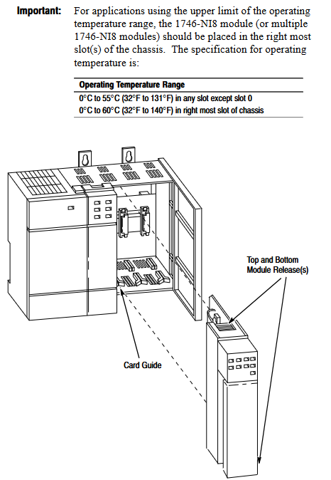
Run basic configuration
(1) Module identification and addressing
ID code setting: The corresponding ID code (Class 1:3526, Class 3:12726) needs to be entered in the programming software. Early versions of RSLogix 500 only supported Class 1 and need to be upgraded to v1.30+to support Class 3.
Memory Mapping:
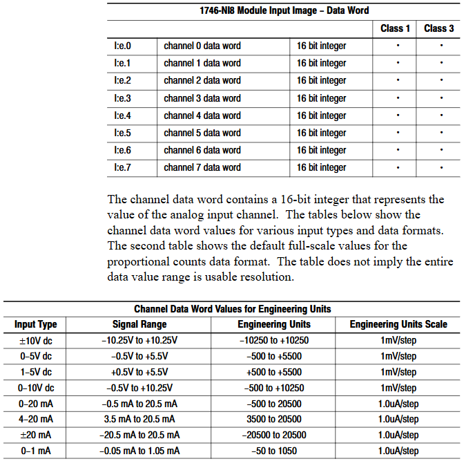
Class 1: Output image O: e.0-O: e.7 consists of 8 channel configuration words, while input image I: e.0-I: e.7 consists of 8 channel data words;
Class 3: The output image contains an additional O: e.8-O: e.11 (2 sets of scaling upper and lower limits), and the input image I: e.8-I: e.15 consists of 8 channel status words.
(2) Key parameter calculation
Module update time: The total sampling conversion time for all enabled channels is 0.75ms for a single channel and 6.0ms for 8-channel full configuration (independent of filtering frequency).
Channel response time:
Start time (enable until status word update): 101-107ms;
Shutdown time (from disabled to data reset): 1-7ms;
Reconfigure time (modify configuration): 101-107ms (excluding data format modifications).
Filtering and Anti aliasing:
The filtering frequency determines the step response (such as achieving 1% accuracy in 730ms for 1Hz filtering, and only 0.5ms without filtering);
Aliasing frequency=1/(number of enabled channels x 0.00075), channel 1 is 1333Hz, and channel 8 is 167Hz. It is necessary to ensure that the signal frequency is lower than the aliasing frequency.
Channel configuration and data processing
(1) Detailed Explanation of Configuration Words
Each channel configuration word (16 bits) defines the channel working mode, and the key bits have the following meanings:
Description of Range Function Options
The voltage (± 10V/1-5V/0-5V/0-10V) and current (0-20mA/4-20mA/± 20mA/0-1mA) of the 0-2 input type should be consistent with the DIP switch
3-5 data format engineering unit (1mV/1 μ A step) Scaled-for-PID(0-16383)、 Proportional counting (-32768-32767), NI4 compatible format, Class 3 user-defined
6-7 open circuit state is only valid for 4-20mA, with optional zero value, upper limit value, and lower limit value
8-10 filtering frequency 000=no filtering, 001=75Hz, 010=50Hz, 011=20Hz, 100=10Hz, 101=5Hz, 110=2Hz, 111=1Hz
11 channel enable 1=enabled (participating in sampling), 0=disabled (data reset)
12-15 reservation needs to be set to 0
(2) Data scaling
The digital output of the module needs to be converted into actual engineering units (such as temperature and pressure), supporting multiple scaling methods. Examples are as follows:
Engineering unit: directly corresponding to physical quantities (such as 4-20mA corresponding to 100-500 ℃, data word 5500 → 247.5 ℃);
Scaled for PID: adapted to SLC PID instructions, 0 corresponds to lower limit, 16383 corresponds to upper limit (e.g. 4-20mA corresponds to 212-932 ° F, data word 5500 → 453.71 ° F);
User defined (Class 3): Set two sets of zoom ranges through O: e.8-O: e.11 and map them proportionally (e.g. 0-10V corresponds to 0-200psi, data word 16600 → 166psi).
(3) Status word monitoring (Class 3)
The input images I: e.8-I: e.15 are channel status words, and the key bits provide feedback on the operating status
Position 0-2: Current input type;
Position 3-5: Current data format;
Bit 11: Channel enable status (1=enabled);
Bit 12: Open circuit error (1=detected);
Bit 13: Over range error (1=input exceeds upper limit);
Bit 14: Under range error (1=input exceeds lower limit);
Bit 15: Configuration error (1=invalid configuration word).

Example of trapezoidal logic
Provide ladder diagram examples of typical programming scenarios, including:
Initialization configuration: Use the first scan bit (S: 1/15) to copy the preset configuration word (stored in the N10 file) to the module output image area (such as O: 3.0-O:3.7) through the COP instruction, and batch enable 8 channels.
PID interface: Set the channel data to Scaled for PID format and directly use it as a process variable (PV) for PID instructions without intermediate scaling (e.g. I: 3.0 → PID control block N11:23).
Fault alarm: Monitor the open circuit error bit of the Class 3 status word (such as I: 3.8/12), trigger the output point (such as O: 2.0) to drive the alarm light.
Diagnosis and troubleshooting
(1) LED status interpretation
Solution to the cause of module status light channel status light malfunction
Always on, always on. Normal operation without operation required
Constant flashing, open circuit/over range/configuration error 1. Check wiring and sensors; 2. Confirm that the configuration word is valid; 3. Check the status word to locate the error type
Extinguish module fault/not powered on 1. Check the power supply of the backplane; 2. Re plug and unplug the module; 3. Contact technical support
- OMRON
- ABB
- General Electric
- EMERSON
- Honeywell
- HIMA
- ALSTOM
- Rolls-Royce
- MOTOROLA
- Rockwell
- Siemens
- Woodward
- YOKOGAWA
- FOXBORO
- KOLLMORGEN
- MOOG
- KB
- YAMAHA
- BENDER
- TEKTRONIX
- Westinghouse
- AMAT
- AB
- XYCOM
- Yaskawa
- B&R
- Schneider
- KONGSBERG
- NI
- WATLOW
- ProSoft
- SEW
- ADVANCED
- Reliance
- TRICONEX
- METSO
- MAN
- Advantest
- STUDER
- DANAHER MOTION
- Bently
- Galil
- EATON
- MOLEX
- DEIF
- B&W
- ZYGO
- Aerotech
- DANFOSS
- Beijer
- Moxa
- Rexroth
- Johnson
- WAGO
- TOSHIBA
- BMCM
- SMC
- HITACHI
- HIRSCHMANN
- Application field
- XP POWER
- CTI
- TRICON
- STOBER
- Thinklogical
- Horner Automation
- Meggitt
- Fanuc
- Baldor
- SHINKAWA
- Other Brands
- UniOP
- KUKA
- Iba
- Beckhoff
- ADLINK
-
 Sigmatek AI075 Analog Input Module
 -
 SIGMATEK TO161 20-007-161 Module
 -
 SIGMATEK CIC011 Module
 -
 SIGMATEK AE0000318502 Hand Terminal Pendant
 -
 Sigmatek Krauss Maffei PC323-K Control Unit
 -
 Sigmatek Krauss Maffei PC321-K Control Cabinet PC
 -
 SIGMATEK CIV521 Control Module
 -
 SIGMATEK C-IPC-171 Industrial PC
 -
 SIGMATEK MDP101-L DIAS Drive Network Module
 -
 Sigmatek Krauss Maffei PC323-K Control Cabinet PC
 -
 SIGMATEK CRCH081 C-SLIDES Temperature Module
 -
 Sigmatek PC301-E6 Industrial PC SSD
 -
 Sigmatek SDI101 S-SLIDES Safety Input Module
 -
 Sigmatek CIV521 VARAN Control Module
 -
 Kollmorgen Sigmatek AKM42G-ANCNGBB0 Servo Motor
 -
 Sigmatek PC 521 Process Controller
 -
 Sigmatek Geode LX800 12-780-012 Industrial PC
 -
 Sigmatek STO081 S-DIAS Safety Output Module
 -
 Sigmatek SCP111 S-DIAS Safety CPU Module
 -
 Sigmatek CDI161 Industrial I O Module
 -
 Sigmatek Wiring Board V2 DIAS 05-250-023
 -
 Sigmatek CP102 20-004-102 S-DIAS CPU Module
 -
SIGMATEK SLIDES CNC 115 Module
-
 SIGMATEK DCC080 05-700-080-2 Control Module
 -
SIGMATEK MDD 121 Drive Axis Module
-
 SIGMATEK CIO011 C-DIAS Multi I/O Module
 -
SIGMATEK CIV512 Servo Drive
-
 SIGMATEK CM5V020 12-250-021-K Wiring Module
 -
 SIGMATEK CIO011 12-013-011 Multi I/O Module
 -
SIGMATEK 01-450-031 C-IPC Industrial Computer
-
SIGMATEK AKM24D-ANBNGBB0 Servo Motor
-
 DEMAG NC4 LP0001289.03 Control Module
 -
 Sigmatek ETEK Industrial PC C-IPC with Option Module
 -
 Sigmatek AO081 20-010-081 Analog Output Module
 -
 Sigmatek CNC 031 Positioning Module
 -
Sigmatek CP731-K 20-004-731-K CPU Module
-
Sigmatek MDD 3320-JR-A Drive Module
-
 Sigmatek PM Servo Motor AKM52K-ANC2GBB0
 -
Sigmatek MDP 101 09-403-101 Power Module
-
Sigmatek S-SLIDES AO046 Analog Output Module
-
Sigmatek ICA111 20-102-111 Interface Module
-
 SIGMATEK DCP646 Module 05-004-646
 -
SIGMATEK SDI101 Digital Input Module 20-891-101
-
 SIGMATEK S3330-2 Directional Gyro Altitude Instrument
 -
SIGMATEK MDP102-1 Controller
-
 SIGMATEK SMT 01-230-321 Touch Screen
 -
SIGMATEK Krauss Maffei PC301-K 01-310-301-K Industrial PC with 8GB SSD
-
 SIGMATEK ETT731 01-230-731 Built-in Touch Terminal
 -
SIGMATEK CIV521 Control Module
-
 SIGMATEK DME 128 Module 05-005-128
 -
 SIGMATEK SCP111-S 20-890-111-S S-DIAS Safety CPU Module
 -
 Sigmatek SCP111 S-DIAS Safety CPU
 -
Sigmatek CRIF081 Interface Module
-
Sigmatek CP112-1 S-DIAS CPU Module
-
 Sigmatek MDD121-L DIAS Drive Axis Module
 -
 Sigmatek C-IPC 01-450-024 Industrial PC
 -
Sigmatek SDD215-23 SLIDES Drive
-
 Sigmatek DPS001 DIAS System Components
 -
Sigma-Tek 4000B-30 Directional Gyro
-
 Sigmatek SDD340-46 SDD Series Drive
 -
 Sigmatek CEZ221 Euromap67 I O Module
 -
 SIGMATEK VI021 Interface Module
 -
SIGMATEK CP731-K Control Module
-
SIGMATEK Krauss Maffei PC321-K Industrial PC
-
SIGMATEK ET322 Operator Terminal
-
SIGMATEK CP102 Control Module 24VDC
-
SIGMATEK SRO021 Relay Output Module
-
 SIGMATEK DCP640 DIAS Central Unit
 -
 SIGMATEK MDD 121 Drive Axis Module
 -
SIGMATEK AI043 Analog Input Module
-
 ENOTEC OXITEC 5000 SME-53310000 Oxygen Analyzer
 -
SIGMATEK Krauss Maffei PC301-K 01-310-301-K Industrial PC
-
 SIGMATEK SDD310-23 VARAN Servo Drive
 -
 SIGMATEK CDM 163 and CIC 011 C-DIAS Input Modules
 -
SIGMATEK MDP 101-1 Power Module
-
 SIGMATEK CM5V020 Wiring Circuit with CTMS020
 -
SIGMATEK CCP521 C-DIAS Processor Module
-
 SIGMATEK MDP 101-K Power Module
 -
SIGMATEK ETEK C-IPC 733MHz VIA Eden 7000
-
 SIGMATEK DCP 643 DIAS PLC CPU Module
 -
SIGMATEK TAE121 12-200-121 Operator Terminal
-
Sigmatek TMS012-T Injection Moulding Technology Module
-
Sigmatek MDD 121-1 Controller
-
Sigmatek CDM167 Module
-
Sigmatek DCP082 DIAS Central Unit
-
 Sigmatek ETT731 Built-In Terminal Touch
 -
Sigmatek CCP521 C-DIAS Processor Module
-
 Sigmatek Krauss Maffei PC301-K Control Cabinet PC
 -
 Sigmatek CIC-21 C-DIAS CAN Module
 -
Sigmatek CIO-011 Multi I O Module
-
Sigmatek 01-450-152D C-IPC 152 Industrial PC
-
SIGMATEK 01-450-024 C-IPC 128MB VIA 733MHz
-
SIGMATEK CCL-081 C-DIAS Processor Module
-
SIGMATEK CP311 20-004-311 Module
-
 SIGMATEK EP00000262 SLIDES MIDI I O-V3 Controller
 -
SIGMATEK TMS012-T Slides Technology Module
-
SIGMATEK MDD111-1 Drive Axis Module
-
 SIGMATEK MDP101-1 PLC Module
 -
 SIGMATEK CP111 S-DIAS Processor Module
 -
 DEMAG ErgoControl Sigmatek NC4 Display Unit
 -
 SIGMATEK DCP642 Module
 -
 Sigmatek Demag NC4 9617.067.03 Control Module
 -
Sigmatek DCP 643 Central Processing Unit
-
Sigmatek VI 021 S-SLIDES VARAN Interface Module
-
 Sigmatek SDD340-46 Servo Drive 14kVA
 -
Sigmatek DSI021 Slide Siemens Interface
-
Sigmatek CCL912 C-SLIDES CPU PSU Module
-
Sigmatek ETV1521 VARAN Control Panel
-
 Sigmatek ET322 Operator LCD Terminal
 -
 Sigmatek MDD1111 DIAS Drive Module
 -
Sigmatek CAM123 Module
-
 SIGMATEK CP111 VARAN Ethernet Controller
 -
 SigmaTek MDD 111 Axle Module
 -
SIGMATEK CIO013 C-DIAS I O Module
-
 SIGMATEK AKM52K-ANC2GBB0 Servomotor 640VDC
 -
 SIGMATEK ETT321 01-230-321 Touch Screen
 -
 SIGMATEK NC4Kompakt 01-250-010-D Safety Controller
 -
 SIGMATEK CIO011 C-DIAS Multi I O Module
 -
SIGMATEK MDD 121-1 Drive Axis Module
-
SIGMATEK CDM163 Control Module
-
Sigma-Tek 4000HR-3 Heading Reference Directional Gyro
-
Sigmatek DIAS DAI 883 Analog Input Module
-
Sigmatek 0332.554.03 Printed Circuit Board Card
-
 Sigma Tek 5000B-36 Attitude Gyro 8130
 -
Demag NC4 0332.554.03 Sigmatek Control Board
-
Sigmatek IPC Pentium 300 CF Industrial PC
-
Sigmatek MDP 102 PLC Module
-
 Sigmatek DTO163 Digital Output Module


