
WAGO 221 series LEVER-NUTS ® Compact splicing connector
Core value: Achieving a 40% volume reduction without sacrificing connection performance, while simplifying operation processes and improving installation safety, becoming a "full scene adaptive product" in the field of electrical connections.
Core technology: Continuing and optimizing WAGO's patented lever technology, wire clamping and fixation can be completed without the need for additional tools.
WAGO 221 series LEVER-NUTS ® Compact splicing connector
Product basic information
1. Product positioning
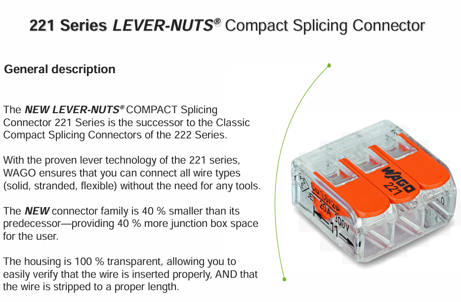
Iterative relationship: The successor to the classic compact splicing connector of the 222 series, with a core upgrade focused on "space optimization+operational convenience+safety visualization".
Core value: Achieving a 40% volume reduction without sacrificing connection performance, while simplifying operation processes and improving installation safety, becoming a "full scene adaptive product" in the field of electrical connections.
Core technology: Continuing and optimizing WAGO's patented lever technology, wire clamping and fixation can be completed without the need for additional tools.
2. Target market and core application scenarios
Applicable fields: covering multiple scenarios such as traditional electrical installation, mobile devices, industrial control, etc. Core applications include:
Building electrical: wiring of junction boxes, wiring of lighting fixtures, connection of wall switches and socket circuits;
Industrial control: motor lead docking, internal control circuit wiring in control cabinets, sensor and actuator wiring;
Mobile devices: mobile electrical equipment with limited space such as RVs, emergency vehicles, and ships;
Other scenarios: internal wiring of household appliances, maintenance and modification of small electrical equipment.
Adapt to core requirements: Electrical connection scenarios that require compatibility with multiple wire types, pursuit of compact installation space, and emphasis on operational efficiency and installation safety.
Detailed explanation of core features and advantages
1. Compatible with all wire types, suitable for a wide range of specifications
Compatibility type: It supports solid wires, multi strand twisted wires, and flexible fine twisted wires without the need to replace connectors or adapter accessories, solving the adaptation problem of different wire connections.
Specification coverage:
Wire diameter (AWG standard): AWG 24-AWG 12 (corresponding to wire diameters of 0.2mm ² -4mm ², with a minimum support of 0.14mm ² for flexible wires);
Adaptation scenario: It can cover weak signal lines (such as sensor signal lines) to medium current power lines (such as small motor power lines).
Advantage value: Reduce spare parts inventory, one connector can meet multiple wiring needs, and reduce procurement and management costs.
2. Ultra compact design, optimizing space utilization
Volume upgrade: Compared to the 222 series, the overall volume has been reduced by 40%, and a single connector takes up less space.
Actual benefits: In space limited scenarios such as junction boxes and equipment interiors, more redundant space can be saved, which can accommodate more line connections and facilitate line sorting during later maintenance.
Installation flexibility: With its compact size, it supports multi-directional installation and can be flexibly arranged in narrow gaps and dense circuits.
3. Transparent shell design, visual security guarantee
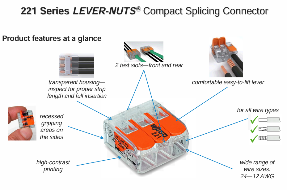
Core function: The shell is 100% transparent, allowing for intuitive observation of two key installation points:
Wire insertion status: Confirm whether the wire is fully inserted into the designated position to avoid poor contact caused by "virtual connection" or "half insertion";
Compliance of wire stripping length: Quickly verify whether the wire stripping length meets the requirements to prevent short circuits caused by excessive stripping and poor contact caused by insufficient stripping.
Safety value: Through visual inspection, the installation error rate is reduced, and the cost of troubleshooting caused by wiring problems in the later stage is reduced. It is especially suitable for quality control in batch installation scenarios.
4. Upgrade operational convenience and reduce labor costs
Leverage operation optimization: The operating force for lever opening and closing is significantly lower than that of the 222 series, making the operation more effortless and suitable for long-term, large-scale wiring scenarios (such as construction project wiring).
Grip design: There is a concave grip area on the side, which increases the friction between the hand and the connector. Even when operating with gloves, it can be stably grasped to avoid slipping.
Tool free feature: No additional tools such as pliers or screwdrivers are required. The wire can be clamped and disassembled by manually opening and closing the lever, simplifying the operation process and improving installation efficiency.
Reusable: Supports multiple opening and closing operations, adapts to scenarios that require repeated disassembly and assembly such as temporary wiring, line adjustment, and equipment maintenance, and improves product reuse.
5. Practical functional design, adapted to meet the needs of multiple scenarios
Dual test slot design: Both the front and rear ends of the connector are equipped with test slots. Regardless of the installation direction or the density of surrounding circuits, test probes can be easily inserted, making it convenient for debugging operations such as conductivity testing and voltage measurement after installation.
High contrast label: The transparent shell is printed with black technical parameter labels (such as voltage, current, wire specifications), which are clear and easy to read, making it convenient for installation personnel to quickly confirm whether the product is suitable for the current scene and avoid model misuse.
Shell protection performance: The shell is made of high-strength engineering plastic, which has a certain degree of dust and light collision resistance, and is suitable for indoor and outdoor general electrical environments (non waterproof design, not suitable for humid or underwater scenes).
Product model and specification parameters
1. Product model and core configuration
Model, number of wire cores, shell color, lever color, core configuration features
221-412 2-core transparent orange dual wire channel, compatible with 2-channel wire splicing
221-413 3-core transparent orange three wire channel, compatible with 3-channel wire splicing
221-415 5-core transparent orange five wire channel, compatible with 5-wire splicing
Packaging form: All are individually packaged and supplied in bulk according to standard specifications (the standard packaging specification is 100 pieces/box, subject to the supplier's configuration).
2. Key technical parameters (based on international standards)
Technical indicators UL standard (North American market) ENEC standard (European and global markets) Remarks
Rated voltage 600V 450V, suitable for different regional power grid voltage standards
The maximum rated current of 20A 32A is determined based on the wire diameter and heat dissipation conditions
Maximum operating temperature 105 ° C T-Mark 85 ° C, suitable for high temperature environments (such as inside equipment)
Solid wire adaptation range AWG 24-AWG 12 0.2mm ² -4mm ² wire diameter correspondence: AWG24 ≈ 0.2mm ², AWG12 ≈ 4mm ²
Multi strand wire adaptation range AWG 24-AWG 12 0.2mm ² -4mm ² supports multi strand wires with twisted strands ≤ 36 strands
Flexible wire adaptation range AWG 24-AWG 12 0.14mm ² -4mm ² Suitable for fine twisted flexible wires (such as motor leads)
Contact resistance ≤ 5m Ω (initial value) ≤ 5m Ω (initial value) ensures low loss conductivity and reduces heat generation
Insulation resistance ≥ 100M Ω (500V DC) ≥ 100M Ω (500V DC) to ensure insulation performance and avoid leakage risk
3. Physical and mechanical properties
Shell material: transparent polycarbonate (PC), with high strength, impact resistance, and high temperature resistance characteristics;
Leverage material: Orange engineering plastic, with good mechanical strength and fatigue resistance (can be opened and closed repeatedly ≥ 100 times);
Conductive component material: high conductivity brass, surface treated with tin plating to enhance conductivity and oxidation resistance;
External dimensions (taking the 2-core model as an example): length x width x height ≈ 22mm x 12mm x 8mm (specific subject to the actual product);
Installation method: There is no fixed installation requirement, it can be freely placed in the junction box or fixed to the wiring harness with zip ties.
Product core advantages and competitive differences (compared to the 222 series)
Compare the core upgrade points of WAGO 221 series and WAGO 222 series (previous generation products) in terms of dimensions
The product has a small volume (reduced by 40% compared to the previous generation), which greatly improves space utilization and is suitable for narrow scenarios
Low operating force (lever operation is more effortless) reduces the manual intensity of batch installation to a moderate extent
The shell design is fully transparent, supporting visual inspection of semi transparent/opaque installation to enhance safety and facilitate quality control
The test slot is designed with dual front and rear test slots, with no directional restrictions and a single test slot. There are installation direction requirements to improve debugging convenience
Grip design with concave side grip area, no dedicated grip design, improved operational stability, and anti glove slippage
Installation and usage precautions
1. Installation steps
Wire processing: According to the connector identification requirements, strip the insulation layer of the wire (recommended stripping length 8-10mm, matching the length of the internal wiring terminal of the connector);
Leverage opening: Pull up the orange lever of the connector to 90 °, and the internal clamping mechanism will open, entering the wire insertion state;
Wire insertion: Fully insert the processed wire into the corresponding wiring hole of the connector, ensuring that the metal core of the wire is completely in contact with the internal conductive components and there is no insulation layer extending into the wiring hole;
Clamping and fixing: Press the lever down to the closed state, and hearing a "click" sound indicates that the clamping is in place and the wire is reliably fixed;
Visual inspection: Confirm through the transparent shell that the wire insertion depth and stripping length are compliant, and there is no exposed core wire or insulation layer clamping situation;
Test verification: Insert probes into the front and rear test slots for conductivity or voltage testing to confirm proper connection.
2. Key points for safe use
Voltage and current limitations: strictly follow the rated voltage (600V/450V) and maximum current (20A/22A) specified in UL/ENEC standards to avoid overloading causing heating or damage;
Environmental temperature requirements: Use within the temperature range of -40 ° C-105 ° C (UL standard)/85 ° C (ENEC standard) to avoid shell embrittlement or seal failure caused by high or low temperature environments;
Wire adaptation requirements: It is not allowed to insert wires beyond the specification range, or wires without stripped insulation layer, to avoid poor contact, short circuit or connector damage;
Installation environment: Avoid use in damp, dusty, and corrosive gas environments. If installation is required in such environments, protective enclosures or sealing measures must be taken in conjunction;
Reuse restriction: Although it supports reuse, it is recommended to disassemble and assemble it no more than 100 times to avoid lever fatigue or internal clamping mechanism failure.
Product delivery and procurement information
1. Packaging specifications
Conventional packaging: 100 pieces/box, each box containing product certification and installation instructions;
Batch packaging: 1000 pieces/box (suitable for engineering bulk procurement), packaged in moisture-proof and pressure resistant cardboard boxes.
2. Quality certification and warranty
Core certification: UL certification (North American market access), ENEC certification (European market access), in compliance with IEC 60998-2-2 standard (safety standard for low-voltage electrical connectors);
Warranty period: The product comes with a 2-year quality guarantee after leaving the factory. Under normal usage conditions, any malfunctions caused by material or manufacturing defects can be replaced free of charge.
- OMRON
- ABB
- General Electric
- EMERSON
- Honeywell
- HIMA
- ALSTOM
- Rolls-Royce
- MOTOROLA
- Rockwell
- Siemens
- Woodward
- YOKOGAWA
- FOXBORO
- KOLLMORGEN
- MOOG
- KB
- YAMAHA
- BENDER
- TEKTRONIX
- Westinghouse
- AMAT
- AB
- XYCOM
- Yaskawa
- B&R
- Schneider
- KONGSBERG
- NI
- WATLOW
- ProSoft
- SEW
- ADVANCED
- Reliance
- TRICONEX
- METSO
- MAN
- Advantest
- STUDER
- DANAHER MOTION
- Bently
- Galil
- EATON
- MOLEX
- DEIF
- B&W
- ZYGO
- Aerotech
- DANFOSS
- Beijer
- Moxa
- Rexroth
- Johnson
- WAGO
- TOSHIBA
- BMCM
- SMC
- HITACHI
- HIRSCHMANN
- Application field
- XP POWER
- CTI
- TRICON
- STOBER
- Thinklogical
- Horner Automation
- Meggitt
- Fanuc
- Baldor
- SHINKAWA
- Other Brands
- UniOP
- KUKA
- Iba
- Beckhoff
-
 Basler DECS-200-2L Digital Excitation Control
 -
 Basler BE1-47N Voltage Phase Sequence Relay
 -
 Basler AEC63-7 Analog Excitation Controller 220-277V
 -
 Basler BE1-50/51B-107 Overcurrent Relay
 -
 Basler Electric BE1‑32R BE1‑E1P‑BON0F Protective Relay
 -
 Basler BE1-25 Solid State Time Overcurrent Relay M1EA6PA5S1F
 -
 Basler MVC 232 Manual Voltage Control Module 90 37000 103 60VAC 55VDC
 -
 Basler RAL6144-16GM Racer GigE Line Scan Camera
 -
 Basler SSR 63-12 Static Voltage Regulator
 -
 Basler BE1-51A Overcurrent Relay
 -
 Basler BE1-87T Solid State Protective Relay
 -
 Basler SR4A2B01B3A Static Voltage Regulator
 -
 Basler SSR 32-12 Static Voltage Regulator
 -
 Basler TRR00696 Transformer 1KVA 115V
 -
 Basler DECS-100-B15 AVR Replacement
 -
Basler BE1-27 Under-Voltage Relay
-
 Basler ACA2000-50GM Interface Module
 -
 Basler AEC63-7 Analog Excitation Controller
 -
 Basler PRS 250 Veri-Sync Relay
 -
 Basler SR4A-2B15B3A Static Voltage Regulator
 -
Basler BE1-32R Power Relay
-
Basler SR8A-2B06B3E Static Voltage Regulator
-
Basler BE1-81 O/U Frequency Relay
-
 Basler BE1-51A-K2E-W6M-B1N0F Overcurrent Relay
 -
Basler BE1-851 Overcurrent Relay G3A1S1 – 48-125V AC/DC
-
 Basler BEI-51 Overcurrent Relay – NSN 5945-01-293-2363
 -
Basler Electric L301KC Protective Relay – L301KC
-
 Basler DECS-100-B15 Automatic Voltage Regulator – Generator AVR
 -
 Basler SR4A-2B15B3A Static Voltage Regulator – SR4A2B15B3A
 -
 Basler UF 312 Under Frequency Protective Module – 9094700100
 -
Basler Electric MVC 232 Manual Control Module – 60VAC 55VDC 20A
-
Basler PRS 250 Veri-Sync Relay – Generator Synchronizing Relay
-
 Basler DECS-100-A05 Digital Regulator Review
 -
 Basler AEM-2020 Analog Expansion Module Specs
 -
 Basler DECS-100-B15 Digital Excitation Specs
 -
Basler Electric 9125600106 Regulator Component
-
Basler BE1-51A-K1E-W6M-B1N0F Overcurrent Relay
-
 Basler MVC-301 MVC 300 Excitation Controller
 -
 Basler SSR 32-12 Static Voltage Regulator
 -
 Basler 9-2849-00-101 Control Module
 -
Basler BE1-51A Overcurrent Relay
-
 Basler BE1-51/27R Overcurrent Relay
 -
 Basler BE1-51 Overcurrent Relay
 -
 Basler SR8A-2B15B3A Static Voltage Regulator
 -
 Basler BE32965001 Transformer and Timer Board
 -
 Basler 9174700100 EL200-7 Excitation Limiter
 -
 Basler BE2000E AVR Voltage Regulator
 -
Basler BE1-87G Differential Relay
-
 Basler BE21834001 Generator Control Module
 -
Basler DECS-100-B15 AVR
-
 Basler D90 96801 100 PCB Card
 -
 Basler XR2002F Voltage Regulator (110 VAC, 48-480 Hz)
 -
 Basler SR8A-2B14B3A Regulator
 -
 Basler 9561500100 Module
 -
 Basler DECS-400 BE1-11 System
 -
 Basler DECS-100-B15 Excitation Control
 -
 Basler SCP 210 Frequency Controller
 -
Basler SR4A-2B15B3A Static Voltage Regulator
-
Basler BE1-32R Power Relay
-
 Basler PIA2400-17GM Power Interface Adapter
 -
 Basler MVC 232 Manual Voltage Control Module
 -
 Basler SSR 32-12 Static Voltage Regulator
 -
Basler 5MW AVR Generator Voltage Regulator
-
 Basler VR63-4B Voltage Regulator
 -
Basler DECS-100-A05 AVR for Engine Generator
-
Basler DECS-100-B15 Automatic Voltage Regulator
-
Basler BE1-32R Directional Power Relay
-
Basler BE1-87B Differential Relay
-
 Basler UFOV 260A Protective Module
 -
 Basler 9-2614-02-100 PCB Rev M
 -
Basler DECS-100-B15 Digital AVR
-
 Basler 9284900103 PS DECS-400N
 -
 Basler D4N3H1U Intertie Protection
 -
 Basler DECS-100-B15 A15 AVR
 -
 Basler KR4F Voltage Regulator
 -
 Basler BE26434 T14 Transformer
 -
 Basler SR8A-2B15B3A Regulator
 -
 Westinghouse 774B472A12 AR Relay
 -
Basler DECS-100-B15 AVR
-
Basler XR2002F Regulator 110V
-
Basler SR125-E Static Regulator
-
Basler SSR 125-12 Regulator
-
Basler MOC2599 Motor Pot
-
 Basler BE1-DFPR Feeder Relay
 -
 Basler CBS 305 Current Boost
 -
Basler BE1-25 AutoSync
-
Basler MVC 300 Voltage Control
-
 Basler BE3-25A AutoSync
 -
 Basler KR7FF Static Regulator
 -
Basler 90-49000-100 Regulator
-
 Basler 880 kVA Dry Type Transformer Specs
 -
Basler Electric BE1-25 Sync-Check Relay Specs
-
 Basler SSR 125-12 Voltage Regulator Specs
 -
 Basler Electric BE1-851 Overcurrent Relay Review
 -
Basler Electric 149D930G02 Control Sub-Assembly
-
 Basler Electric BE1-81O/UT Frequency Relay Specs
 -
 Basler Electric BE1-51/27C Overcurrent Relay
 -
 Basler Electric 149D956G02 Industrial Component
 -
Basler Electric BE1-51A Overcurrent Relay Specs
-
 Basler Electric BE1-40Q Loss of Excitation Relay
 -
Basler DECS-200 Excitation Control System
-
 Basler DECS-200 Voltage Regulator 56-277V AC / 125V DC
 -
Basler BE1-87T Transformer Differential Relay
-
 Basler RDP-110-S1 Protection Relay
 -
 Basler BE1-700V Digital Protective Relay
 -
 Basler BE1-951 Overcurrent Protection System
 -
 Basler DECS-300 Digital Excitation Control
 -
 Basler DECS-200 Digital Excitation Control
 -
 Basler DECS-200-1C Excitation Control System
 -
Basler DECS-200-1L Digital Excitation Control
-
 Basler Electric BE1-GPS Generator Protection System
 -
Basler Electric DECS-200-1C Digital Excitation Controller
-
 Basler Electric DECS125-15 Excitation Control with Power Module
 -
Basler Electric BE1-87G Differential Relay
-
 Basler Electric BE1-11 Protection System I5A3M2P2N0EA00
 -
Basler Electric DECS-200-1C Excitation Control System
-
Basler Electric BE1-11g Generator Protection Relay
-
Basler Electric DECS 125-15-B2C1 V2.0.9 Excitation Control
-
Basler Electric BE1-81O/UT3ED1JA7N2F Frequency Relay
-
Basler Electric BE1-81O/UT3EE1YB7N1F Frequency Relay
-
 Basler Electric DECS-200-1L Digital Excitation Control System
 -
Basler DECS125-15-B2C1 Excitation Control
-
 Basler 9507900205 SSR Retrofit Voltage Regulator
 -
 Basler BE2000E Digital Voltage Regulator
 -
 Basler BE1-GPS Generator Protection System
 -
Basler DECS-250-CN1CN1N Digital Excitation Control
-
 Basler DGC-2020 Genset Controller
 -
Basler BE1-81O UT3ED1LA7N0F Frequency Relay (Variant)


