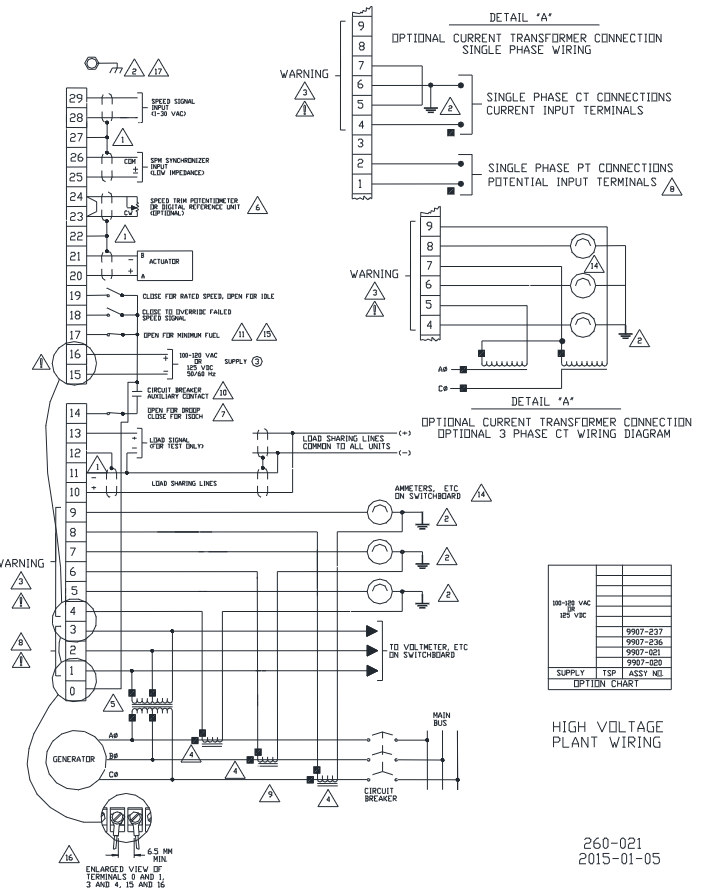
Woodward 2301A 9907 series electronic load distribution and speed controller
Strong current cables (power supply, CT/PT) should be wired separately from signal cables to avoid parallel laying; Severe electromagnetic interference scenarios require the use of metal conduits or double shielded cables.
3. Installation inspection process
Mechanical inspection: The actuator and the connecting rod of the prime mover are not loose/stuck, and the actuator lever does not touch the mechanical limit when the fuel is at its minimum position (to prevent the inability to stop the machine).
Wiring inspection: Check the power polarity, CT/PT phase, terminals are not loose, and the shielding layer is connected correctly according to the wiring diagram.
Sensor inspection: The gap between the magnetic head and the gear is 0.25-1.0mm, and there are no metal debris; Measure the sensor resistance (100-300 Ω) before powering on to determine if there is an open/short circuit.

Operation and debugging process
1. Initial settings before startup
All potentiometers must be pre-set according to the following requirements to avoid overload or overspeed during startup:
Initial setting function of potentiometer
Rated speed minimum (counterclockwise to the bottom) to avoid excessive speed during startup
Reset the middle position to adjust the speed and restore the speed
Speed stability when adjusting load changes in the middle position of gain (GAIN)
Ramp TIME (clockwise to the end) extends the acceleration time to prevent overspeed during startup
Low IDLE SPEED Maximum (clockwise to the bottom) ensures stable idle after starting
Adjust the load distribution ratio in the middle position of the load gain (LOAD GAIN)
DROOP Minimum (counterclockwise to the bottom) Initial default synchronization mode
ACTUATOR COMPENSATION for diesel/gas engines: 2; Gasoline engine/turbine: 6 compensating actuator response delays
Start Fuel Limit Maximum (clockwise to the bottom) to prevent excessive fuel smoke during startup
2. Startup and dynamic debugging
(1) Startup steps
Close the "rated speed" contact (terminal 19), close the droop contact (terminal 14), and set to synchronous mode.
Connect the power to the controller and calibrate the speed using a signal generator: Connect terminals 28-29, set the rated frequency, and slowly adjust the "rated speed" potentiometer to stabilize the actuator voltage at the intermediate value (not maximum/minimum).
Start the prime mover and observe if the speed is stable. If there is a rapid fluctuation (hunting), decrease the "gain" counterclockwise; If there is a slow fluctuation, increase the "reset" clockwise.
(2) Key parameter calibration
Low idle adjustment: Disconnect the "rated speed" contact (terminal 19) and adjust the "low idle" potentiometer counterclockwise to the recommended idle speed (higher than the fuel mechanical limit speed).
Load gain calibration: When a single unit is running synchronously, load to full load and adjust the "load gain" potentiometer to make the voltage between terminals 11 (-) and 13 (+) 6.0V (3.0V at half load, proportionally adjusted).
Sag adjustment:
Isolated load: Disconnect the droop contact, adjust the rated speed under no-load, and adjust the "droop" potentiometer to the target droop rate under full load (e.g. 5% droop corresponds to 60Hz no-load → 57Hz full load).
Grid parallel connection: calculate the full load frequency (rated frequency × (1+droop rate)), set the frequency at no-load, close the circuit breaker and then adjust "droop" and "load gain" to full load.
3. Parallel operation debugging
When multiple units are connected in parallel, the following conditions must be met:
All units have the same no-load speed (synchronous mode).
The load gain voltage is consistent (full load 6.0V).
CT/PT phase consistency: Ensure the CT wiring phase is correct and avoid circulating current through the "phase correction process" (see pages 23-25 of the manual).
Load distribution line connection: All units have 10 (+) and 11 (-) terminals connected in parallel, and the shielding layer is continuously grounded.
Troubleshooting and Maintenance
1. Common fault handling
The manual provides a detailed troubleshooting table, and the core faults and solutions are as follows:
Possible causes and solutions for the fault phenomenon
The prime mover cannot start, the actuator does not operate, and the polarity of the power supply is reversed/there is no voltage; The fuel limit for starting is too low; Check the polarity and voltage of the power supply when the speed signal is not cleared and the fault circuit is not cleared; Turn up the 'Start Fuel Limit' clockwise; Short circuit terminals 18-16 (temporary shielding fault signal)
Overspeed/smoking ramp time too short during startup; The rated speed is set too high; Turn up the "ramp time" clockwise when the fuel restriction is not in effect; Reduce the 'rated speed' counterclockwise; Delay starting for 1 second after power on (ensure fuel restriction is activated)
Uneven load distribution and differences in no-load speed of units; Inconsistent load gain voltage; CT phase error calibration of all units' no-load speed; Unified load gain voltage to 6.0V (full load); Re execute CT phase correction
- ABB
- General Electric
- EMERSON
- Honeywell
- HIMA
- ALSTOM
- Rolls-Royce
- MOTOROLA
- Rockwell
- Siemens
- Woodward
- YOKOGAWA
- FOXBORO
- KOLLMORGEN
- MOOG
- KB
- YAMAHA
- BENDER
- TEKTRONIX
- Westinghouse
- AMAT
- AB
- XYCOM
- Yaskawa
- B&R
- Schneider
- Kongsberg
- NI
- WATLOW
- ProSoft
- SEW
- ADVANCED
- Reliance
- TRICONEX
- METSO
- MAN
- Advantest
- STUDER
- KONGSBERG
- DANAHER MOTION
- Bently
- Galil
- EATON
- MOLEX
- DEIF
- B&W
- ZYGO
- Aerotech
- DANFOSS
- Beijer
- Moxa
- Rexroth
- Johnson
- WAGO
- TOSHIBA
- BMCM
- SMC
- HITACHI
- HIRSCHMANN
- Application field
- XP POWER
- CTI
- TRICON
- STOBER
- Thinklogical
- Horner Automation
- Meggitt
- Fanuc
- Baldor
- SHINKAWA
- Other Brands


