
Westinghouse 2400i digital inverter generator
Power parameters: displacement of 79cm ³, maximum speed of 5000rpm, intelligent adjustment of speed with load (operating at the lowest speed in ECO mode)
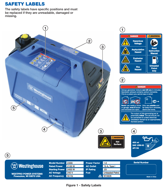
Fuel emission hose: located at the bottom of the left side of the aircraft, used to drain the fuel from the tank (such as during long-term storage or when the fuel deteriorates).
Safety operation rules (including risk avoidance)
1. Environmental safety requirements
The operating position should meet the following requirements: good outdoor ventilation, away from doors, windows, ventilation openings, tents, etc. (to prevent the accumulation of carbon monoxide); The ground is flat and hard (to avoid vibration and tilting during operation, which may cause fuel/oil leakage); Maintain a distance of at least 1.8m from combustible materials such as wood, hay, paint, etc., and maintain a heat dissipation space of at least 0.5m from other equipment.
Prohibited from use in the following scenarios: confined spaces (indoor, garage, basement), damp ground (waterlogged, muddy), thunderstorm weather, and high dust concentration environments (such as construction site dust areas).
Extreme environmental response: When operating at high temperatures (>35 ℃), it is necessary to operate in a cool place and avoid direct sunlight; When the temperature is low (<0 ℃), winter specific engine oil (such as 5W-30) should be used, and the engine block can be preheated before starting (to avoid open flame heating).
2. Fuel safety operation
Preparation before refueling: Turn off the engine and wait for at least 10 minutes for it to cool down (the muffler temperature can reach over 400 ℃, which can easily ignite the fuel); Clean the oil around the fuel filler to prevent impurities from entering the fuel tank.
Refueling operation: Use a dedicated refueling pot to slowly refuel, with the oil level not exceeding the red limit ring in the fuel tank (reserve 5-10% expansion space); If fuel spills, immediately wipe it clean with a dry cloth and wait for it to evaporate before starting the engine.
Fuel storage: Backup fuel should be stored in a qualified fuel container, in a ventilated, cool, and away from sources of fire, for a period of no more than 3 months (with the addition of fuel stabilizers, it can be extended to 6 months).
Forbidden operation: Do not refuel while the engine is running; Prohibit using fuel to clean equipment; Do not place fuel containers on the generator or near heat sources.
3. Electricity safety regulations
Extension cable selection: 240V AC extension cables must comply with AS/NZS 3199:2007 standards, using 15A heavy-duty three core cables (core cross-sectional area ≥ 1.5mm ²), with a length not exceeding 25m (1.5mm ²) or 40m (2.5mm ²); The length of the 12V DC extension cable shall not exceed 3.5m, and the cross-sectional area of the wire core shall be ≥ 1.0mm ².
Load calculation method:
Pure resistance load (light bulb, heater, rice cooker): starting power=operating power, total operating power ≤ 2100W.
Inductive loads (air conditioning, water pump, motor): starting power=operating power x 1.2 (small portable equipment) or 3.5 (large fixed equipment), total starting power ≤ 2400W.
Example: 1.5kW air conditioner (operating power 1500W), starting power=1500 × 3.5=5250W>2400W, cannot be driven separately; 0.8kW water pump (operating power 800W), starting power=800 × 1.2=960W, can be driven.
Grounding requirements: The generator itself has an equipotential connection system and does not require separate grounding; If connecting fixed equipment or using in humid environments, a certified electrician must connect the grounding terminal to the grounding electrode (such as a metal grounding rod).
Emergency response: In case of equipment tripping, heating, or odor during power consumption, immediately disconnect the load, shut down the generator, and troubleshoot before use.
4. Personnel safety protection
Wear goggles (to prevent fuel splashes and debris from entering the eyes) and gloves (to prevent oil contamination and burns) during operation; Long hair should be curled up to avoid getting caught up in moving parts.
Children and pets are prohibited from entering within a 1m radius of the generator; Operators need to be familiar with the operating procedures and avoid operating under the influence of alcohol or fatigue.
Emergency situation handling: In case of fuel leakage, immediately stop operation, stay away from the scene, and clean up after the fuel evaporates; If a fire occurs, use ABE or BE type fire extinguishers to extinguish it (it is prohibited to directly extinguish electrical fires with water); If you feel dizzy or nauseous after inhaling carbon monoxide, immediately transfer to a well ventilated area and seek medical attention in severe cases.
Step by step operation guide (including key details)
1. Preparation for the first use of the new machine
Open the box inspection: Open the packaging and take out the generator and accessories (400mL SAE 15W-40 engine oil, fuel can, screwdriver, spark plug socket wrench, dust cover, instruction manual); Check that the appearance of the generator is undamaged, the components are not loose, and the sockets and switches are functioning properly.
Oil filling:
Place the generator on a level surface and open the left oil maintenance cover.
- OMRON
- ABB
- General Electric
- EMERSON
- Honeywell
- HIMA
- ALSTOM
- Rolls-Royce
- MOTOROLA
- Rockwell
- Siemens
- Woodward
- YOKOGAWA
- FOXBORO
- KOLLMORGEN
- MOOG
- KB
- YAMAHA
- BENDER
- TEKTRONIX
- Westinghouse
- AMAT
- AB
- XYCOM
- Yaskawa
- B&R
- Schneider
- KONGSBERG
- NI
- WATLOW
- ProSoft
- SEW
- ADVANCED
- Reliance
- TRICONEX
- METSO
- MAN
- Advantest
- STUDER
- DANAHER MOTION
- Bently
- Galil
- EATON
- MOLEX
- DEIF
- B&W
- ZYGO
- Aerotech
- DANFOSS
- Beijer
- Moxa
- Rexroth
- Johnson
- WAGO
- TOSHIBA
- BMCM
- SMC
- HITACHI
- HIRSCHMANN
- Application field
- XP POWER
- CTI
- TRICON
- STOBER
- Thinklogical
- Horner Automation
- Meggitt
- Fanuc
- Baldor
- SHINKAWA
- Other Brands
- UniOP
- KUKA
- Iba
- Beckhoff
-
 Basler D90 96801 100 PCB Card
 -
 Basler XR2002F Voltage Regulator (110 VAC, 48-480 Hz)
 -
 Basler SR8A-2B14B3A Regulator
 -
 Basler 9561500100 Module
 -
 Basler DECS-400 BE1-11 System
 -
 Basler DECS-100-B15 Excitation Control
 -
 Basler SCP 210 Frequency Controller
 -
 Basler SR4A-2B15B3A Static Voltage Regulator
 -
 Basler BE1-32R Power Relay
 -
 Basler PIA2400-17GM Power Interface Adapter
 -
 Basler MVC 232 Manual Voltage Control Module
 -
 Basler SSR 32-12 Static Voltage Regulator
 -
 Basler 5MW AVR Generator Voltage Regulator
 -
 Basler VR63-4B Voltage Regulator
 -
 Basler DECS-100-A05 AVR for Engine Generator
 -
 Basler DECS-100-B15 Automatic Voltage Regulator
 -
 Basler BE1-32R Directional Power Relay
 -
 Basler BE1-87B Differential Relay
 -
 Basler UFOV 260A Protective Module
 -
 Basler 9-2614-02-100 PCB Rev M
 -
Basler DECS-100-B15 Digital AVR
-
 Basler 9284900103 PS DECS-400N
 -
 Basler D4N3H1U Intertie Protection
 -
 Basler DECS-100-B15 A15 AVR
 -
 Basler KR4F Voltage Regulator
 -
 Basler BE26434 T14 Transformer
 -
 Basler SR8A-2B15B3A Regulator
 -
 Westinghouse 774B472A12 AR Relay
 -
Basler DECS-100-B15 AVR
-
Basler XR2002F Regulator 110V
-
Basler SR125-E Static Regulator
-
 Basler SSR 125-12 Regulator
 -
 Basler MOC2599 Motor Pot
 -
 Basler BE1-DFPR Feeder Relay
 -
 Basler CBS 305 Current Boost
 -
 Basler BE1-25 AutoSync
 -
 Basler MVC 300 Voltage Control
 -
 Basler BE3-25A AutoSync
 -
 Basler KR7FF Static Regulator
 -
 Basler 90-49000-100 Regulator
 -
 Basler 880 kVA Dry Type Transformer Specs
 -
 Basler Electric BE1-25 Sync-Check Relay Specs
 -
 Basler SSR 125-12 Voltage Regulator Specs
 -
 Basler Electric BE1-851 Overcurrent Relay Review
 -
Basler Electric 149D930G02 Control Sub-Assembly
-
 Basler Electric BE1-81O/UT Frequency Relay Specs
 -
 Basler Electric BE1-51/27C Overcurrent Relay
 -
 Basler Electric 149D956G02 Industrial Component
 -
Basler Electric BE1-51A Overcurrent Relay Specs
-
 Basler Electric BE1-40Q Loss of Excitation Relay
 -
 Basler DECS-200 Excitation Control System
 -
 Basler DECS-200 Voltage Regulator 56-277V AC / 125V DC
 -
Basler BE1-87T Transformer Differential Relay
-
 Basler RDP-110-S1 Protection Relay
 -
 Basler BE1-700V Digital Protective Relay
 -
 Basler BE1-951 Overcurrent Protection System
 -
 Basler DECS-300 Digital Excitation Control
 -
 Basler DECS-200 Digital Excitation Control
 -
 Basler DECS-200-1C Excitation Control System
 -
Basler DECS-200-1L Digital Excitation Control
-
 Basler Electric BE1-GPS Generator Protection System
 -
Basler Electric DECS-200-1C Digital Excitation Controller
-
 Basler Electric DECS125-15 Excitation Control with Power Module
 -
 Basler Electric BE1-87G Differential Relay
 -
 Basler Electric BE1-11 Protection System I5A3M2P2N0EA00
 -
Basler Electric DECS-200-1C Excitation Control System
-
Basler Electric BE1-11g Generator Protection Relay
-
Basler Electric DECS 125-15-B2C1 V2.0.9 Excitation Control
-
 Basler Electric BE1-81O/UT3ED1JA7N2F Frequency Relay
 -
Basler Electric BE1-81O/UT3EE1YB7N1F Frequency Relay
-
 Basler Electric DECS-200-1L Digital Excitation Control System
 -
Basler DECS125-15-B2C1 Excitation Control
-
 Basler 9507900205 SSR Retrofit Voltage Regulator
 -
 Basler BE2000E Digital Voltage Regulator
 -
 Basler BE1-GPS Generator Protection System
 -
Basler DECS-250-CN1CN1N Digital Excitation Control
-
 Basler DGC-2020 Genset Controller
 -
 Basler BE1-81O UT3ED1LA7N0F Frequency Relay (Variant)
 -
 Basler BE1-81O UT3EE1YA9S0F Frequency Relay (Variant)
 -
Basler BE1-81O Over/Under Frequency Relay
-
Basler DECS125-15 Digital Excitation Control
-
Basler Electric BE1-951 Overcurrent Protection System
-
 Basler Electric BE1-700V Digital Protective Relay
 -
 Basler Electric APR63-5 Automatic Voltage Regulator
 -
Basler Electric BE1-851 Overcurrent Protection System
-
Basler Electric DECS-250-LN1SN1N Excitation Control
-
 Basler Electric BE1-87T Transformer Differential Relay
 -
Basler Electric DECS-200-1L Excitation Control System
-
 Basler Electric 9310300100 DECS-300 Excitation Control
 -
 Basler Electric SSE-N 125-4.5KW Shunt Exciter Regulator
 -
 Basler Electric DGC-2020HD-5NS1DNSBA Genset Controller
 -
Basler Electric BE1-81-O/UT3EE1JB7N1F Frequency Relay
-
Basler Electric BE1-81T1EE1WA0N1F Frequency Relay
-
 Basler Electric BE1-25M1EA6PN5R1F Sync-Check Relay
 -
 Basler Electric BE1-GPS Generator Protection System
 -
Basler Electric DECS-250-LN1SN1N Excitation Control Rev V
-
 Basler Electric DECS-250-CN2CN1N Excitation Control
 -
Basler Electric BE1-50/51B-207 Overcurrent Relay
-
Basler Electric DECS-300-C0N0 Excitation Control System
-
Basler Electric DECS-200 Digital Excitation Control System
-
Basler Electric DECS-250-LN1CN1N Excitation Unit
-
Basler Electric DECS-250 LN2SA1D Excitation Unit Specs
-
Basler Electric BE1-87T Transformer Relay Review
-
Basler Electric BE1-11 Protection System
-
Basler Electric BE1-GPS100-E4N1H1N Protection System
-
 Allen-Bradley 442G-MABH-R Safety Module
 -
 Beckhoff CX1030-0111 PLC Assembly Profile
 -
 FANUC IC693CPU364 PLC Module
 -
 Orange Denmark Type 200816 220 PLC Specs
 -
 OMRON C200H-SNT31 Sysmac PLC Module
 -
 Allen Bradley 20AB022A3AYNANC0 PowerFlex 70
 -
 OMRON C200HW-PCU01 Position Control Unit
 -
 ABB AO845A-eA Analog Output Module
 -
 OMRON CJ1M-CPU22 CPU Unit
 -
 Allen Bradley 100-E265ED11 Contactor
 -
 Honeywell 51304511-100 Interface Module
 -
 SOLEXY BXF3S0101N0018 Gateway Module
 -
 OMRON CJ2H-CPU65 CPU Unit
 -
 Automation Direct GS2-45P0 AC Drive
 -
 M68-2000 2-Axis Motion CNC Controller
 -
 OMRON CJ1M-CPU11 V3.0 PLC CPU Unit
 -
 OMRON CJ1W-NC413 4-Axis Positioning Controller
 -
 OMRON 3G2A3-PRO16 Programming Console HMI
 -
 Siemens 3VT8440-2AA04-2GA2 Molded Case Circuit Breaker
 -
 Siemens 3RT5045 Contactor Series
 -
 OMRON C200HS-CPU01-E SYSMAC PLC Controller
 -
 OMRON C500-NC103-E Positioning Control Unit
 -
 OMRON CJ1W-TC001 Temperature Control Unit


