
Triconex 3624 Digital Output Module
Tricon controller: It adopts the third mock examination redundancy (TMR) architecture to achieve fault tolerance, integrates three independent parallel control systems and comprehensive diagnostic functions, ensures no single point of failure through the "three out of two" voting mechanism, and achieves high integrity, error free, and uninterrupted process operation.
TMR architecture details: Three identical channels independently and parallelly execute control programs, digital I/O is verified through dedicated software and hardware voting, and analog input adopts median selection; The channels are isolated from each other, and a single channel failure does not affect other channels. The faulty module can be replaced online.
Triconex 3624 Digital Output Module
Overview of the Core of Tricon Fault Tolerant Control System
Core Definition and Architecture
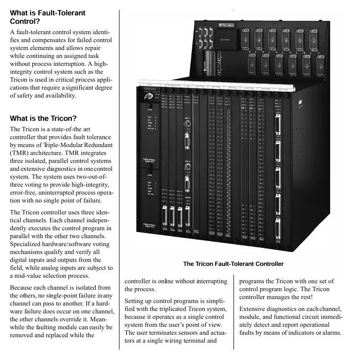
Fault Tolerant Control: capable of identifying and compensating for faulty control units, allowing for repairs without interrupting processes, suitable for critical process applications that require high safety and availability.
Tricon controller: It adopts the third mock examination redundancy (TMR) architecture to achieve fault tolerance, integrates three independent parallel control systems and comprehensive diagnostic functions, ensures no single point of failure through the "three out of two" voting mechanism, and achieves high integrity, error free, and uninterrupted process operation.
TMR architecture details: Three identical channels independently and parallelly execute control programs, digital I/O is verified through dedicated software and hardware voting, and analog input adopts median selection; The channels are isolated from each other, and a single channel failure does not affect other channels. The faulty module can be replaced online.
Key Features
No single point of failure; Support 3, 2, or 1 main processor to run until shutdown; Fully implemented and transparent triple transformation; Comprehensive system diagnosis; Complete I/O module series; Provide dual I/O and single I/O modules for safety critical and limited availability requirements; Remote I/O can be up to 7.5 miles (12 kilometers) away from the main processor; Support simple online module maintenance; Has extremely high reliability and availability.
Typical application scenarios
Emergency Safety Shutdown (ESD): protects key units such as refineries and petrochemical/chemical plants, monitors parameters such as pressure and feed rate, avoids false tripping of traditional relay systems, has sensor integrity detection, integrated shutdown and control functions, and can be connected to monitoring data highways.
Boiler flame safety: Integrating boiler protection, start stop safety interlock, and flame safety functions, replacing traditional discrete components, improving resource utilization, and maintaining or exceeding the safety of electromechanical protection systems.
Turbine control system: realizes the control and protection of gas/steam turbines, integrates speed control and start stop sequence, avoids unplanned shutdowns through I/O module hot standby, and automatically activates the standby module in case of faults.
Marine fire and gas protection: supports online replacement of faulty modules, built-in diagnostic management module, wiring and sensor faults, simulated fire and gas detectors can be directly connected, replacing traditional fire and gas panels, saving space and ensuring high safety and availability.
Detailed specifications of 3624 digital output module
Module basic information
Type: TMR (the third mock examination redundancy), with supervised function.
Nominal voltage: 24 VDC.
Output points: 16 points, shared.
Electrical parameters
Voltage range: 16-30 VDC, maximum voltage 36 VDC.
Voltage drop: Typical value<1.5 VDC.
Power module load:<10 watts.
Current rating: maximum 0.7 A per point, maximum surge current of 4.8 A within 10 ms.
Minimum required load: 30 mA.
Load leakage current: maximum 4 mA.
Point isolation: minimum 1500 VDC.
Fuse: None (self-protection).
Function and Diagnosis
Monitoring function: By using voltage and current loop circuits, combined with online diagnosis, the output switch, on-site circuit, and load status can be verified, and faults such as on-site power loss/fuse melting, load open circuit/loss, load misoperation short circuit, load power-off short circuit, etc. can be detected; The POWER alarm is activated when the on-site voltage cannot be detected, and the LOAD alarm is activated when the load cannot be detected.
Module status diagnosis: equipped with PASS (module passes self-test), FAILT (module fault), ACTION (module activation) indicator lights, with ON/OFF status indicator lights at each point, color code Turquoise Green.
Compatibility and Installation
Supporting hot standby modules requires a separate external terminal panel (ETP) and cable interface with the Tricon backplane; The module adopts a mechanical key control design to prevent accidental installation into the wrong slot; On site wiring requires connecting the on-site power supply to each output point of the on-site terminal, with the output designed to provide current to the on-site equipment.
System configuration and hardware components
System Composition
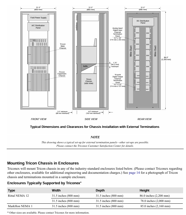
Composed of one main chassis and up to 14 extended or remote extended (RXM) chassis, up to 15 chassis can support 118 I/O modules and communication modules, and can connect OPC clients, Modbus devices, other Tricon controllers, Ethernet (802.3) external host applications, and Foxboro, Honeywell DCS.
Chassis Layout and Configuration Rules
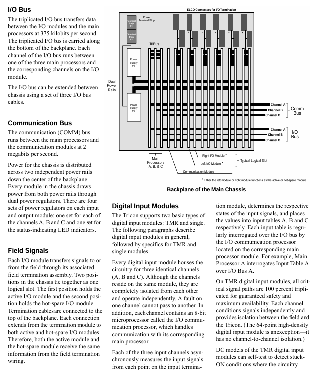
Main Chassis: There are two power modules on the left side and three main processors on the right side. The remaining space is divided into six logical slots for I/O and communication modules, as well as one COM slot without a hot spare position. Each logical slot contains two physical spaces (active module and optional hot spare module); Address 1 requires three 3008 model main processors (Tricon v9.6 and above) and two power modules.
Expand Chassis: The layout is similar to the main Chassis, but provides 8 logical slots for I/O modules; The length of the I/O bus cable is usually up to 100 feet (30 meters), and can reach up to 1000 feet (300 meters) in restricted applications. The address needs to be between 2-15 and unique, requiring two power modules connected to channels A, B, and C through a triple I/O bus cable.
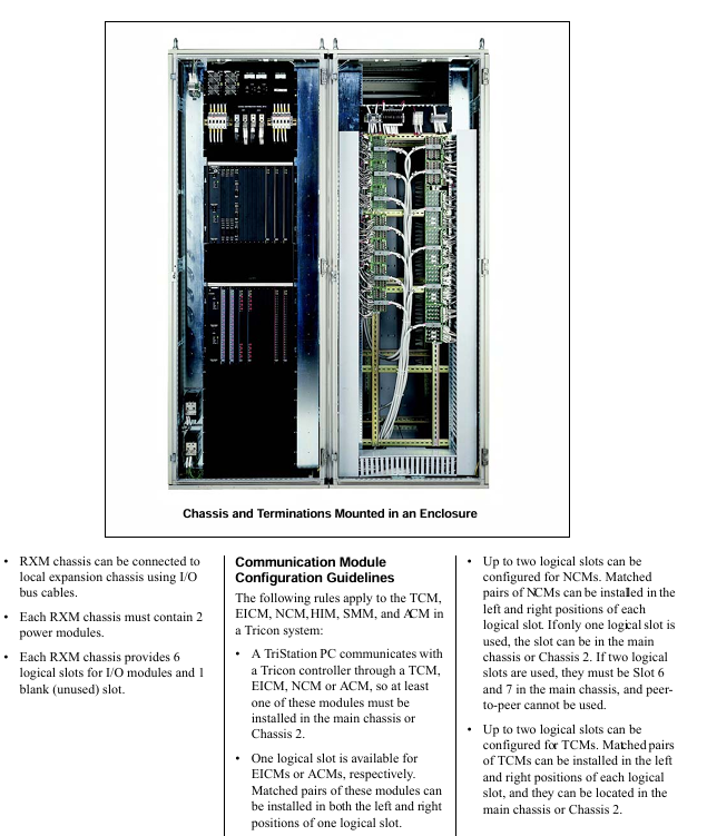
RXM Chassis: Used in scenarios where the total length of I/O bus cables exceeds 100 feet (30 meters), with addresses 2-15 and unique; An RXM Chassis needs to be located within 100 feet (30 meters) of the main Chassis, with built-in main RXM module groups (usually supporting 3 groups), each group can support 3 remote sites, with each site up to 7.5 miles (12 kilometers) away from the main site. Remote sites require RXM Chassis and remote RXM module groups, with the main and remote RXM module groups connected by 6 fiber optic cables; Provide 6 I/O module logic slots and 1 blank slot, requiring two power modules that can be connected to the local expansion Chassis via I/O bus cables.
Core hardware component specifications
Power module: each Chassis is equipped with two, and any module can operate under full load and rated temperature, supporting online replacement; Convert the line power supply to a DC power supply suitable for the Tricon module, with an input of at least 240 watts per power module; The alarm contact will activate when the module is missing, there is a conflict between hardware and control program logic configuration, the module is faulty, the main processor detects a system fault, the main power supply of the power module is faulty, or there is a warning of "low battery" or "over temperature" in the power module; There are multiple models available, such as 8310 (120 VAC/VDC), 8311 (24 VDC), 8312 (230 VAC), with an output power of 175 watts (at 140 ° F/60 ° C), an output voltage of 6.5 VDC ± 1%, a maximum output current of 27 A (in 140 ° F/60 ° C environment), input and output isolation>1000 VAC or 1500 VDC, and an over temperature sensor triggered when the internal temperature is>181 ° F (83 ° C), usually corresponding to an ambient temperature of 140 ° F (60 ° C) or above.
Main processor module (Model 3008): Used in Tricon v9.6 and above systems, each system requires 3 main Chassis modules, which independently communicate with the I/O subsystem and execute user control programs; Includes Motorola MPC860 32-bit 50 MHz microprocessor, 16 MB DRAM (without battery backup), 32 KB SRAM (battery backup), 6 MB Flash PROM; TriBus communication speed of 25 Mbps, 32-bit CRC protection, 32-bit DMA and complete isolation; The I/O bus and communication bus processors are Motorola MPC860 32-bit 50 MHz; Equipped with multiple status indicator lights such as PASS, FAULT, and ACTION; Support sequence of events (SOE) and time synchronization, protect user programs and maintain variable integrity for at least 6 months during power outages, powered by dual power modules and main Chassis power rails.
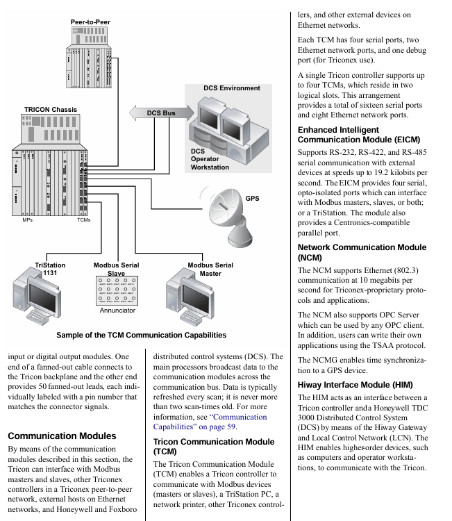
Communication module: Multiple types meet different communication needs, such as the Tricon Communication Module (TCM) that supports communication with Modbus devices TriStation PC、 Communication between network printers, other Tricon controllers, and Ethernet devices, including 4 serial ports, 2 network ports, and 1 debugging port. A single system can support up to 4 ports and should be located in two logical slots; Enhanced Intelligent Communication Module (EICM) supports RS-232/422/485 serial communication, including 4 serial ports and 1 parallel port. A single system can support up to 2 ports, which need to be located in one logical slot; The Network Communication Module (NCM) supports Ethernet (802.3) communication, including 2 BNC interfaces and 1 RS-232 serial port, supports OPC Server and TSAA protocols, and NCMG supports GPS time synchronization; The Safety Manager Module (SMM) connects Tricon to Honeywell TDC 3000 UCN; Hiway interface module (HIM) connects Tricon with Honeywell TDC 3000 Hiway gateway and LCN; Advanced Communication Module (ACM) connects Tricon with Foxboro I/A Series DCS.
Remote Expansion Module (RXM): Supports I/O modules located several kilometers away from the main Chassis, consisting of three identical modules, serving as relays and extenders for the Tricon I/O bus, providing ground loop isolation; There are multimode fiber (4200-3 main, 4201-3 remote, maximum distance 1.2 miles/2 kilometers) and single-mode fiber (4210-3 main, 4211-3 remote, maximum distance 7.5 miles/12 kilometers) models, with a communication speed of 375 kbps and indicator lights such as PASS, FAULT, and ACTION.
On site terminal options
Terminal product type
External Terminal Panel (ETP): a passive printed circuit board that facilitates on-site wiring, transmits signals between the site and I/O modules, supports I/O module replacement without interfering with on-site wiring; The on-site signals can be collected in a separate enclosure up to 99 feet (30 meters) away from Tricon; The standard panel includes terminal blocks, resistors, fuses, and other components, suitable for lines 24-12 (0.3-2.1mm ²), with some having current limiting resistors or fuses with fuse indication; There are also basic panels (including connectors and terminal blocks only, users need to equip other components themselves), hazardous area (non flammable) panels (suitable for Zone 2, Class 1, Division 2, certified by T Ü V), panels with intermediate relays (suitable for load current>2A or voltage>115 VAC scenarios), digital input bypass panels (32 pre wired switches, including master key switch and redundant 24 VDC power terminals), panels with signal conditioners (supporting RTD, thermocouple, 4-20 mA transmitter, 16 points/panel, compatible with 1-5V output signal conditioners) and other types.
Faned Out Cables: A low-cost alternative to ETP, with one end connected to a Tricon backplane and the other end having 50 labeled 22 wires with pin numbers, suitable only for digital I/O modules. The standard length is 10 feet (3 meters) and can be customized up to 99 feet (30 meters). The last two digits of the model indicate the length (feet).
Terminal configuration and protection
Configuration options: Non common ground terminal (each point can be connected to an independent power supply), common ground terminal (multiple points share one power supply, can be connected to a common ground group of 8 or 16 points); Analog signals can be connected to 3-wire transmitter inputs, voltage inputs, or current inputs; The thermocouple terminal provides a cold junction temperature sensor, the 3706A model's fuse detection relies on the terminal panel, and the 3708E model can be configured through TriStation.
Overcurrent protection: Non basic terminal panels are self protected through single point/on-site power fuses, series resistors, digital and analog output modules; The basic terminal panel requires users to equip themselves with overcurrent protection components.
Module and Terminal Matching Table: The document provides a detailed table that lists various terminal panel models (common ground, non common ground, basic, non flammable, fan out cable, bypass panel, ERT loopback cable/panel) corresponding to each I/O module (such as digital input, digital output, pulse input, relay output, analog input, analog output, thermocouple input module, etc.). For example, the common terminal panel model corresponding to the 3624 digital output module (24 VDC, 16 points, TMR monitoring type) is 9662-610, the basic terminal panel model is 9653-610, the non flammable terminal panel model is 9671-610, and the fan out cable model is 9101-010.
Terminal panel dimensions: The document lists the width (horizontally along the DIN rail), length (vertically along the DIN rail), and height (away from the DIN rail) dimensions of each model of terminal panel, in inches and centimeters. For example, the 9551-110 panel has a width of 3 inches (7.62 centimeters), length of 5 inches (12.7 centimeters), and height of 4.25 inches (10.795 centimeters).
Communication capability
Communication range and supported objects: Tricon can communicate with Modbus master-slave devices, Foxboro I/A Series Nodebus, Honeywell UCN, Honeywell Data Hiway and LCN, Ethernet (802.3) external hosts, other Tricon controllers (peer-to-peer networks), TriStation PC, OPC Server through communication modules.
Details of Key Communication Module Functions
TCM (Tricon Communication Module): Only compatible with Tricon v10.0 and above, supporting communication with TriStation, other Tricon/Rident controllers, Modbus master-slave devices, and Ethernet external hosts; 4 serial ports (configurable as Modbus master/slave, serial port 1 supports Modbus or Trimble GPS, serial port 4 supports Modbus or TriStation, total data rate 460.8 kbps), 2 network ports (4351A/4353 is copper Ethernet, 4352A/4354 is fiber Ethernet, supports TCP/IP, Modbus TCP/IP and other protocols, network port 1 also supports peer-to-peer and peer-to-peer time synchronization protocols); A maximum of 4 units per system, located in two logical slots, do not support hot standby but can be replaced online; The Tricon variable needs to be assigned a 5-digit alias (representing the Modbus message type and variable address) to communicate with Modbus devices.
EICM (Enhanced Intelligent Communication Module, Model 4119A): Supports Modbus master-slave devices TriStation、 Printer communication; 4 serial ports (configurable as Modbus master/slave, supporting RS-232/422/485, up to 7 Modbus master stations per Chassis), 1 parallel port (Centronics compatible); A maximum of 2 units per system, located in one logical slot, do not support hot standby but can be replaced online; The total data rate is 57.6 kbps, Modbus supports RTU or ASCII mode, and Tricon variables need to be assigned aliases.
NCM (Network Communication Module, Model 4329/4329G): Supports Ethernet (802.3) communication at a speed of 10 Mbps, and NCMG supports GPS time synchronization; 2 BNC interfaces (RG58 50 ohm thin cable), 2 external transceiver interfaces (15 pin D-type), and 1 RS-232 serial port; Port 1 supports peer-to-peer and time synchronization protocols (only for Tricon secure networks), while Port 2 supports open networks (TriStation, SOE, OPC Server, etc.); A single logical slot can accommodate 2, working independently and not as a hot backup; External hosts need to access Tricon variables through aliases, which can be extended to a distance of 2.5 miles (4000 meters) through repeaters and standard cables.
SMM (Safety Manager Module, Model 4409): Connect Tricon to Honeywell TDC 3000 UCN as a safety node on the UCN, transmit process information at full network rate, and transmit Tricon alias data and diagnostic information to the operation station in a format familiar to Honeywell operators; Support critical I/O point processing, alarm processing and propagation, alias data reading and writing, Tricon diagnostic reading, write protection, DCS time synchronization, peer-to-peer communication, event sequence transmission, and hot standby functions; 2 isolated UCN ports, data rate 5 MB/s, power load<20 watts, isolated 500 VDC, equipped with multiple status indicator lights.
HIM (Hiway Interface Module, Model 4509): connects Tricon with Honeywell TDC 3000 (via Hiway gateway and LCN) or TDC 2000 (via Data Hiway), supporting communication between high-level devices on LCN/Data Hiway and Tricon; 2 isolated Data Hiway channels, baud rate of 250 kbps, equivalent to 4 extended Data Hiway port addresses, providing 8 Hiway addresses, data refresh<0.5 seconds; Support hot standby, power load<10 watts, isolated 500 VDC, with multiple status indicator lights.
ACM (Advanced Communication Module, Model 4609): connects Tricon with Foxboro I/A Series system as a secure node on Nodebus, transmitting process information at full network rate, and transferring Tricon alias data and diagnostic information to the operation station in a format familiar to Foxboro operators; Support critical I/O point processing, alarm processing and propagation, alias data read and write, Tricon diagnostic read, write protection, I/A Series time synchronization, and hot standby function; BNC supports TriStation, TSAA protocol, and user applications; Multiple ports (BNC, 15 pin D-type AUI, 9-pin RS-423 Nodebus control port, etc.), some ports have a speed of 10 Mbps, the Nodebus control port is 2400 baud, the power load is 20 watts, isolated 500 VDC, and equipped with multiple status indicator lights.
Communication Protocol and Application
Support agreement: TriStation、Modbus(RTU/ASCII/TCP)、TCP/IP、ICMP、SNTP、TSAA、Trimble GPS、 Peer to Peer, peer-to-peer time synchronization, Jet Direct (network printing), etc.
Triconex protocol: Peer to peer protocol (exchanging security and process information between Tricons), time synchronization protocol (maintaining Tricon time consistency in the network), TriStation protocol (master-slave communication between TriStation PC and Tricon, one slave per communication), TSAA protocol (master-slave communication between external hosts and Tricon, used for developing control or monitoring applications).
Triconex applications: TriStation 1131 (for developing, testing, and monitoring Tricon applications), Event Sequence (SOE, for retrieving Tricon events in the network for maintenance and downtime analysis), Enhanced Diagnostic Monitor (for monitoring Tricon hardware and application status), DDE Server (for allowing Windows DDE clients such as Excel to read and write Tricon alias data), OPC Server for Triconex (for allowing OPC clients to read and write Tricon program variables, some modules rely on external Matrikon OPC Server, and some models will have embedded OPC Server).
Network redundancy and configuration rules
Module/Media Redundancy: Install two communication modules (TCM/NCM/ACM) in the same logical slot and connect network nodes with two sets of cables to address issues such as cable breakage and port failures.
External host redundancy: The backup external host is connected to the network, and in the event of a primary host failure, the control program can be restarted on the backup host. All Triconex applications can be loaded onto the primary and backup hosts.
Configuration rule: TriStation PC needs to communicate with Tricon through TCM/EICM/NCM/ACM, and at least one such module needs to be installed in the main Chassis or Chassis 2; Some modules (such as EICM, ACM) have a limit on the number of logical slots, and some modules (such as NCM, TCM) cannot coexist in the same system; If Chassis 2 is equipped with a communication module, it requires an I/O COMM cable (9001 model) instead of a standard I/O bus cable to directly connect to the main Chassis. Chassis 2 can be an I/O expansion Chassis or a main RXM Chassis.
TriStation 1131 Development Platform and Programming
TriStation 1131 Developer’s Workbench
Positioning and compatibility: an integrated tool for developing, testing, and documenting Tricon's safety and critical process control applications, compliant with the IEC 61131 international standard and following the Microsoft Windows graphical user interface guidelines; Different versions have different compatibility, such as v4.1.433 and above being compatible with Tricon 9.5.x-10.1. x, v4.1 supporting Windows NT/2000/XP, v4.0 only supporting Windows NT/2000 (only verifying Windows 2000), and versions below v4.0 only supporting Windows NT.
Core function: Provides three IEC 61131-3 language editors: Function Block Diagram (FBD), Ladder Diagram (LD), and Structured Text (ST), with optional CEMPLE language editor (supporting causal matrix method); Can create programs, functions, function blocks, define controller configurations, declare tag names, test applications in simulators, download and monitor applications.
V4.1 new feature: compatible with Windows 2000/XP; Support the setup of new analog input, digital output, and Tricon communication modules; Automatically save backup project files after downloading, which can be used for recovery; Support writing intermediate ST code to files; The enhanced diagnostic monitor has become an independent application since v4.1.435.
Project Elements and Programming Languages
Project elements: program (highest level executable logic element, one project can support hundreds), function (produces a single result, data is not retained), function block (produces one or more results, needs instantiation, data is retained), data type (defines variable size and characteristics, such as BOOL, DINT, REAL), library (including IEC 61131-3 standard library, Triconex library, Tricon library, user can create custom libraries).
Programming language details:
FBD (Function Block Diagram): A graphical language where elements are blocks and binary and other data are transmitted through connections, similar to a circuit diagram.
ST (Structured Text): A high-level text language similar to PASCAL, supporting Boolean and arithmetic expressions, conditional statements (IF... THEN... ELSE), etc. v4.0 adds arrays, structures, For Loop, Exit, CASE statements, enumeration data types, var external, var test variables.
LD (Ladder Diagram): A graphical language that uses standard symbols to represent relay logic. The basic elements are coils and contacts, which are connected through links and only transmit binary data.
CEMPLE(Cause and Effect Matrix Programming Language Editor): Advanced graphical language, providing two-dimensional matrix association process problems (causes) and corrective actions (results), automatically converted to IEC 61131-3 compatible FBD, supports up to 99 causes, 99 results, 1000 intersections, can call functions/function blocks to evaluate status, supports custom view monitoring, multi-level undo/redo.
Development and testing tools
Controller configuration: Define the modules, communication settings, tag name memory allocation, and operating parameters in the system. The configuration information is included in the control program downloaded to the controller.
Simulator Panel: Connect the emulator, download control programs, test and debug; List program, variable, and tag names, drag variables to the monitoring panel to modify values, support automatic running, single step running, or pause.
Controller Panel: Connect the controller to enable real-time execution of control programs.
Diagnostic Panel: Prior to v4, it was used to monitor the status of MP, CM, and I/O modules and diagnose faults, providing system performance information such as project names and memory sizes; The diagnostic function in v4.1 is integrated into an independent enhanced diagnostic monitor (since v4.1.435).
Documentation and Security: Supports multiple data sorting and project element documentation methods, can print user developed functional blocks and programs, provides standard reports, and can customize Crystal Reports; Provide a password security system, define user and editing, library modification permissions, etc; Audit tracking records project history and program version changes, automatically timestamp key events, and support manual recording of user comments; Can add comments and annotations; Provide an online Help system.
- OMRON
- ABB
- General Electric
- EMERSON
- Honeywell
- HIMA
- ALSTOM
- Rolls-Royce
- MOTOROLA
- Rockwell
- Siemens
- Woodward
- YOKOGAWA
- FOXBORO
- KOLLMORGEN
- MOOG
- KB
- YAMAHA
- BENDER
- TEKTRONIX
- Westinghouse
- AMAT
- AB
- XYCOM
- Yaskawa
- B&R
- Schneider
- KONGSBERG
- NI
- WATLOW
- ProSoft
- SEW
- ADVANCED
- Reliance
- TRICONEX
- METSO
- MAN
- Advantest
- STUDER
- DANAHER MOTION
- Bently
- Galil
- EATON
- MOLEX
- DEIF
- B&W
- ZYGO
- Aerotech
- DANFOSS
- Beijer
- Moxa
- Rexroth
- Johnson
- WAGO
- TOSHIBA
- BMCM
- SMC
- HITACHI
- HIRSCHMANN
- Application field
- XP POWER
- CTI
- TRICON
- STOBER
- Thinklogical
- Horner Automation
- Meggitt
- Fanuc
- Baldor
- SHINKAWA
- Other Brands
- UniOP
- KUKA
- Iba
- Beckhoff
- ADLINK
-
 Rolls Royce H1111.0204 Ship Main Controller
 -
 Basler Electric BE3-32-3AC Reverse Power Relay 9 1376 00 105
 -
 Basler Electric BE3-25-1A1N4 Synch Check Relay 9319100100
 -
 Basler Electric SR4A-2B15B3A Static Voltage Regulator
 -
 Basler Electric SR4A-2B15B3E Static Voltage Regulator
 -
 Basler Electric 9170818100 Solid State Protective Relay
 -
 Basler Electric AEC63-7 Analog Excitation Controller
 -
 Basler Electric 17483 Auxiliary Module
 -
 Basler Electric BE1-59 Over Voltage Relay
 -
 Basler Electric 21600-101 Control Module
 -
 Basler Electric KR2F Generator Voltage Regulator 9056600100
 -
 Basler BE1-CDS Current Differential System
 -
 Basler Electric CBS 212 Current Boost System 9 2650 00 100
 -
 Basler Electric IFM-150 Firing Circuit Chassis
 -
 Basler Electric BE1-60 Voltage Balance Relay C1F A1P D0C3F
 -
 Basler Electric BE1-32R Power Relay A2E D1R A0N0F
 -
Basler Electric BE1-32R Power Relay A2E D1R A0N0F
-
 Basler Electric 8650C80G01 Isolation Transducer PCB Board
 -
 ETEL EA-P2M-300-4/7.5A-0100-01 AccurET Modular 300 Servo Drive
 -
 Basler Electric 87T Transformer Differential Relay
 -
 Basler Electric BE-6868 Power Transformer 5950007559202
 -
 Basler Electric PRS250 Veri-Sync Relay 9088800102
 -
 Basler Electric SCP-250-G-60 VAR Power Factor Controller
 -
 Basler DECS-150 AVR 1NS2V1N1S Voltage Regulator
 -
 Basler UFOV 260A Under Frequency Overvoltage Module
 -
 Basler MOC2 199 Motor Operated Control – Overview and Setup
 -
 Basler BE3-49R-5K5A1 Temperature Relay – Complete Guide
 -
Basler BE 20035 001 Transformer – Technical Data and Installation
-
 Basler BE 02727 001 Transformer – Specifications and Usage
 -
 Basler BE127 Under Voltage Relay – Features and Application Guide
 -
Basler CBS377 Current Boost System – Complete Technical Guide
-
 Basler BE1-87G P/N 9170818100 Differential Relay – In-Depth Specs
 -
Basler BE1-87G Generator Differential Relay – Technical Overview
-
Basler Electric SR4A2B16 SVR Static Voltage Regulator – Complete Guide
-
 Basler Electric 9261500101 Power Supply Module
 -
 Basler Electric AEM-2020 Analog Expansion Module
 -
Basler Electric DGC-2020 Digital Genset Controller 51BRBNEAH001
-
Basler Electric BE1-59N Ground Fault Overvoltage Relay
-
 Basler Electric BE1-59N-A5E-E1L-N0S1F Neutral Overvoltage Relay
 -
Basler Electric MOC2499 Motor Operator Control Potentiometer 9072300430
-
 Basler Electric BE1-50/51M Overcurrent Relay
 -
 Basler Electric 9148100106 MOC3502 Solid State Relay 250VDC 0.25A
 -
 Basler Electric CBS 212 Current Boost System 9265000100
 -
 Basler Electric 10493002 Control Module
 -
Basler BE1-32R D3E E1R A0N1F Power Relay
-
 Basler SR8A2B15B3A Static Voltage Regulator
 -
 Basler IFM-105 Firing Circuit Chassis 9324100105
 -
Basler SR4A2B05B3A Static Voltage Regulator
-
 Basler BE151G1EB6PB0N0F Protective Relay
 -
Basler BE1-59 Electric Over Voltage Relay
-
 Basler 277 Static Programmable Powerline Carrier Channel
 -
 Basler BE1-32R D1E A1P A0N1F Power Relay
 -
Basler SR4A1B07B3A Static Voltage Regulator
-
 Basler Electric BE1-700 Digital Protective Relay
 -
Basler Electric SR8A-2B01B3A Static Voltage Regulator
-
 Basler Electric SR4A-2B01B3E Static Voltage Regulator
 -
 Basler Electric 9017709102 PC Board
 -
Basler Electric SR4A-2B01B3A Static Voltage Regulator
-
 Basler Electric PRS-250 Veri-Sync Relay
 -
 Basler Electric 9066800102 Excitation Support System
 -
Basler Electric BE1-87G Generator Differential Relay 9 1708 18 100
-
 Basler Electric 36T865-2 BE03752001 Power Supply
 -
 Basler Electric M-300 149D940G02 Power Supply
 -
 Basler Electric ACA2040-25GM 4Mp 25Fps Area Scan Camera
 -
 Basler BE1-87G-S1A-A1C-A0N0 Differential Relay
 -
Basler SR8A-2B06B3E Static Regulator SR8A2B06B3E
-
 Basler SCP-210 Frequency Controller 9095400100
 -
 Basler BE1-59-A3E-A1J-N1N3F Overvoltage Relay BE159A3EA1JN1N3F
 -
Basler 9 2011 11 100 Bracket Mounted Terminal Unit
-
Basler 9 1606 00 101 Voltage Regulator
-
 Basler CBS-377 Current Boost System 9109600102
 -
 Basler 8650C72 Exciter Control Module PCB Rev 5
 -
 Basler C2EE1PA0N1F BE1-32R Reverse Power Relay
 -
 ADLINK HPCI-14S12U - Industrial Control Backplane 12PCI Backplane PCI-14S Passive Backplane
 -
-0010.png) ADLINK PCIe-GIE74C - image acquisition card 4-CH GigE Vision PoE+ Frame Grabber
ADLINK PCIe-GIE74C - image acquisition card 4-CH GigE Vision PoE+ Frame Grabber -
-0010_1.png) ADLINK PCI-8164 - control card 4-Axis Advanced Motion Controller Board
ADLINK PCI-8164 - control card 4-Axis Advanced Motion Controller Board -
 ADLINK PCIe-U304 - 4 Port USB3 PCIe Frame Grabbers USB Screw Hole Card
 -
 ADLINK PCI-9112 - Multi-Function Data Acquisition Card DAQ Card
 -
 ADLINK PCI-7432 - 51-12013-0A50 4-CH Isolated Numérique I/O PCI Cartes Digital I/O Card
 -
 ADLINK PCA-6106P3-0C1 REV.C1 - backplane 6-Slot Passive Backplane Board
 -
 ADLINK PCI-7224 - 24-CH Opto-Isolated Digital I/O PCI Board
 -
 ADLINK CPCI-7433R(G) - Digital Input Board Rear I/O CompactPCI Card
 -
 ADLINK EBP-13E4 - 51-46703-0A30 Industrial PC Backplane Passive Backplane
 -
 ADLINK PCIE-HDV62 - Image acquisition card High Definition Video Frame Grabber
 -
 ADLINK EBP-13E4 - 51-46703-0A30 Industrial Backplane Board Passive Backplane
 -
 ADLINK 90111-B1 / CPCI-6770 - PCB CPU MODULE CompactPCI Single Board Computer
 -
 ADLINK PCI-7248 - DATA ACQUISITION PCI CARD 48-CH Parallel Digital I/O Board
 -
 ADLINK PCI-7230 - 51-12003-0a50 board PCI7230 32-CH Isolated Digital I/O Card
 -
 ADLINK PCI2A000CB - 51-20000-0B30 Multi-Function DAQ Card Baseboard
 -
 ADLINK PCI-8134-005 - 4-Axis Motion Controller Card
 -
 ADLINK PCI-7224 - 24-CH Opto-Isolated Digital I/O PCI Card
 -
 ADLINK PCI-7434 - 64-CH Isolated Digital Output Card
 -
 ADLINK PCI-8132 - motion control card 2-Axis Servo & Stepper Controller
 -
 ADLINK PCI-8134 - Motion Controller PCI Card 4-Axis Controller Board
 -
 ADLINK PCI-8164 - Motion Control Card 51-12406-0A40 4-Axis Controller
 -
 ADLINK 51-12001-0C20 - Circuit Board Data Acquisition Interface Module Hardware
 -
 ADLINK NuPR0-840 - industrial control motherboard Full-Size PICMG CPU Board
 -
 ADLINK PCI-7444 - 51-12023-0A10 card 128-CH Isolated Digital Output Board
 -
 ADLINK PCI-1612B - data acquisition card 4-Port RS-232/422/485 Serial Communication Card
 -
 ADLINK PCI-6208V 009 - 8/16-CH 16-Bit Analog Output Cards PCB-I-E-482=6BX3
 -
 ADLINK NUPRO-935A/LV - industrial control motherboard Full-Size PICMG SBC Board
 -
 ADLINK PCI-9114DG - Multi-Function DAQ Card Data Acquisition PCI Card
 -
 ADLINK ACL-7130 - Data acquisition card Isolated Digital I/O Board
 -
 ADLINK ABX-6300D-4E1-BP - board ABX6300D4E1BP Video Interface Expansion Card
 -
 ADLINK CPCI-6940 - CPCI-6940/D1539/M16-0(EA)-000E 6U CompactPCI Processor Board
 -
 ADLINK NuPRO-760 - industrial control motherboard Half-Size PICMG SBC CPU Board
 -
 ADLINK IMB-M42H (G)-0020 - industrial control motherboard LGA1155 Micro-ATX Mainboard
 -
 ADLINK RTV-24 / PCI-MP4S - 51-12519-1C30 4-Channel Real Time Video Capture Board
 -
 ADLINK PCI-8134 - 4-Axis Servo & Stepper Motion Controller Card
 -
 ADLINK MXC-6101D - V.PC000.002.ST.00 Box PC Configurable Embedded Computer
 -
.png) ADLINK PCI-8134A - 51-12421-0A10 Motion Control Card 4-Axis Controller Card
ADLINK PCI-8134A - 51-12421-0A10 Motion Control Card 4-Axis Controller Card -
 ADLINK DIN-100S / DIN-100SA1 - Technology SCSI-II TB 100-PIN Terminal Block Board
 -
.png) ADLINK DIN-812M001 / DIN812M001 - 51-14034-0A1 51140340A1 Terminal Module Breakout Interface
ADLINK DIN-812M001 / DIN812M001 - 51-14034-0A1 51140340A1 Terminal Module Breakout Interface -
_1.png) ADLINK PCI-8164 - Servo motion control 4-Axis Advanced Controller Card
ADLINK PCI-8164 - Servo motion control 4-Axis Advanced Controller Card -
 ADLINK PCIe-GIE64 - Acquisition card GigE Vision PoE+ Frame Grabber
 -
 ADLINK M-302 - Industrial control motherboard ATX PC Board Mainboard
 -
 ADLINK PCI-8134 - Motion Controller PCI Card 4-Axis Controller Board
 -
 ADLINK PCI-RTV24 - Image capture card Analog Video Frame Grabber
 -
 ADLINK PCI-8102 - Motion control card 2-Axis Servo & Stepper Controller Board
 -
 ADLINK PCI-9112 REV.B1 - Card Multi-Function Data Acquisition Card
 -
 ADLINK HSI-DI32-M-N / HSL-TB32-M-DIN - Discrete I/O MODULE Distributed Automation Module System
 -
 ADLINK PCI-7296 - IO card REV.A3 96-CH Parallel Digital I/O Card
 -
-0020.png) ADLINK DIN-814P-A4 / 814Y - terminal board Motion Control Interface Block
ADLINK DIN-814P-A4 / 814Y - terminal board Motion Control Interface Block -
 ADLINK DIN-814P-A4 - 51-14056-0A10 PCB-I-E-2736=ZA01 Screw Terminal Board Breakout
 -
 ADLINK M-322 - motherboard Industrial Control Computer Mainboard
 -
 ADLINK NUPRO-406 REV:B1 - industrial control motherboard Full-Size PICMG CPU Board
 -
 ADLINK AMP-204C - card DSP-Based 4-Axis Advanced Pulse-Train Controller
 -
 ADLINK HPCI14S REV.B1 - industrial computer baseboard 14-Slot Passive Backplane


