
WOODWARD MicroNet TMR ® OpView of 5009 Digital Control System ™ Interface Operation Manual
WOODWARD MicroNet TMR 5009 OpView ™ Operating Interface System Application Guide
Introduction
In the field of industrial automation and turbine control, Woodward's MicroNet TMR 5009 digital control system is renowned for its outstanding reliability and precise control performance. As an important component of the system, OpView ™ The Operator Interface provides an intuitive and efficient touchscreen workstation, allowing operators to remotely monitor system status, adjust control parameters, and execute running commands. This article will be based on the MicroNet TMR 5009 Digital Control System Volume 4 OpView ™ The content of the Interface Manual (manual number 85580V4, revised J) provides a comprehensive analysis of the functions, installation, operation, and safety precautions of the OpView interface, aiming to provide a professional and detailed application guide for engineering and technical personnel, system maintenance personnel, and operators.
1 OpView ™ Overview of the operating interface
1.1 System positioning and functions
OpView ™ The operating interface is a touch screen workstation specifically designed for the Woodward MicroNet TMR 5009 digital speed controller, with the following core functions:
Status monitoring: Real time display of turbine operating parameters, start-up sequence status, generator information, analog input/output, discrete input/output status, etc.
Control operation: Allow operators to adjust control settings, start stop functions, perform valve calibration, overspeed testing, etc.
Alarm and event recording: Provides timestamp alarm and trip records, supports connecting to a serial printer to output hard copies.
Dynamic adjustment and trend analysis: Supports PID parameter adjustment and provides real-time trend charts for system debugging and optimization.
1.2 Compatible models
The OpView hardware models covered in the manual include:
8236-354: Color screen, 25 pin Com B port
8236-513: Color screen, 25 pin Com B port, suitable for Class I, Division 2 hazardous areas
8236-616: Color screen, 25 pin Com B port
8236-617: Color screen, 25 pin Com B port, suitable for Class I, Division 2 hazardous areas
8236-700: Color screen, 9-pin Com B port
8236-701: Color screen, 9-pin Com B port, suitable for Class I, Division 2 hazardous areas
8236-1001: Color screen, 9-pin Com B port

Safety and compliance requirements
2.1 Safety Warning Level
The manual clearly defines the following safety warning levels, which must be strictly followed before operation:
Danger (DANGER): Refers to the risk of death or serious injury if not avoided.
Warning: Indicates that failure to avoid may result in death or serious injury.
CAUTION: Indicates that if not avoided, it may result in minor or moderate injury.
NOTICE: Indicates possible property damage (including damage to control equipment).
Important: Indicates operational skills or maintenance recommendations.
2.2 Key safety measures
Overspeed protection: The turbine must be equipped with an overspeed trip device independent of the control system to prevent personnel injury or equipment damage caused by overspeed operation.
Personal protective equipment (PPE): Appropriate protective equipment must be worn during operation, such as goggles, hearing protection, helmets, gloves, safety boots, etc.
Electrostatic protection: Electronic control components are sensitive to static electricity, and must release body static electricity by contacting a grounded surface before operation to avoid direct contact with circuit board components.
Explosive hazardous environment: Some models (such as when installing F/T relay modules) are not suitable for Class I, Division 2 hazardous areas and must be used in ordinary or non hazardous areas.
2.3 Compliance Statement
Applicability to Hazardous Areas: Some models (such as 8236-513, 8236-617, 8236-701, 8236-703) are suitable for Class I, Division 2, Groups A, B, C, D or non hazardous areas.
Wiring requirements: On site wiring must be at least 75 ° C rated temperature, and special attention should be paid when the ambient temperature exceeds 50 ° C.
CE Mark Compliance: To comply with the European Low Voltage Directive (LVD), the maximum external circuit voltage limit for discrete input and relay output circuits is 18-32 Vdc.
Installation and Configuration
3.1 Mechanical Installation
Installation environment: OpView is designed for panel installation, with a protection level of NEMA 4 and a working temperature range of 0 to 50 ° C (32 to 122 ° F).
Space requirement: Leave at least 2 inches (about 5 centimeters) of space around the device to ensure ventilation, and reserve enough space on the back for wiring.
Fixing method: Depending on the model, 12 mounting bolts or 6 mounting clips can be used for fixing.
3.2 Communication Connection
OpView communicates with the J3 port of the SIO module of the 5009 controller through the Com B port and supports the following communication standards:
RS-232: Transmission distance not exceeding 15 meters (50 feet)
RS-422/RS-485: Transmission distance up to 1200 meters (4000 feet)
The communication configuration depends on the OpView model (9-pin or 25 pin interface) and needs to be set through jumpers or DIP switches. The default communication parameters are:
Protocol type: RTU
Equipment number: 1
Baud rate: 19200
Stop position: 1
Checkpoint: None
3.3 Printer Settings
OpView supports connecting printers through parallel ports to output alarm logs. The printer needs to be configured as:
Baud rate: 9600
Checkpoint: None
Data bits: 8
Stop position: 1
3.4 Initial Settings
After power on, OpView will perform diagnostic tests for approximately a few minutes. If communication with the 5009 controller fails, it may take up to 20 minutes to display the application interface. It is recommended to set the date and time of OpView when using it for the first time. Please refer to page 14 of the manual for specific steps.
Detailed explanation of the operation interface
4.1 Main Menu
The main menu is the hub for accessing other function screens and includes the following key function buttons:
Local/Remote Switching: Used to enable or disable the remote control panel.
Emergency Shutdown (ESD): Adopting a two-step verification process to prevent misoperation.
Alarm log: Directly access the alarm record interface.
Configure password: After entering the password, you can enter the application manager for advanced settings.
4.2 Core Function Screen
(1) Turbine Start Screen
According to the configuration of the 5009 controller, three startup modes are displayed:
Idle/Rated Mode
No idle mode (manual up/down only)
Auto Start Sequence
This screen provides functions such as startup status display, speed setting adjustment, and valve limiter control.
(2) Turbine Run Screen
Display turbine type and application configuration in a graphical manner, supporting:
Frequency control arm/release
Load sharing enabled/disabled
Synchronizer control
Run time statistics
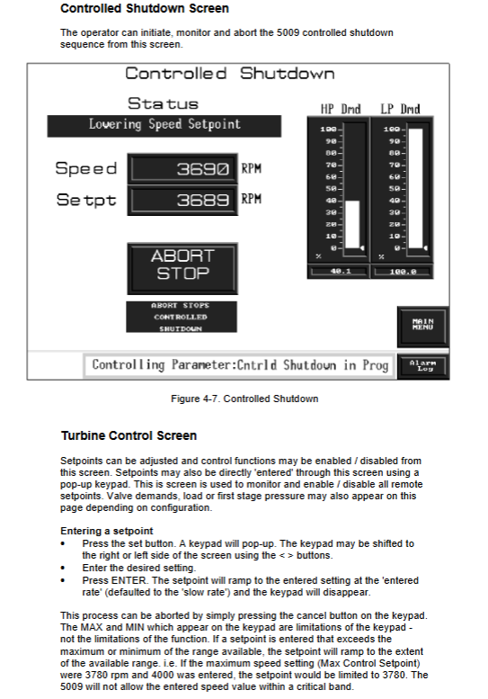
(3) Turbine Control Screen
Allow direct input of set values and input specific numerical values through a pop-up keyboard. Support:
Set value up/down adjustment
Enable/disable remote settings
Valve requirement display
(4) Valve Calibration Screen
After meeting the system license conditions (turbine shutdown, speed below 1000 RPM) and entering the calibration password, valve calibration can be performed. Support:
Valve position adjustment (fast/slow)
Minimum/maximum mA setting
Calibration parameter saving
(5) PID Control Screen
Display all configured PID outputs and set values in the form of a bar chart for easy observation of the interaction between various control loops.
(6) Trend&Dynamics Screens
Provide a one minute trend chart (sampled per second), supporting:
PID parameter adjustment (proportional, integral, derivative)
Trend resolution adjustment
Dynamic parameter saving
4.3 Alarm Management System
OpView provides complete alarm recording function:
Alarm log: displays current alarms (red with asterisks) and historical alarms.
Alarm confirmation and reset: Manage alarm status through ALM ACK and RESET buttons.
Print output: Supports real-time output of alarm events by connecting to a serial printer.
Alarm History: Stores the last 500 alarm records and cannot be cleared.
Password and permission management
OpView adopts a three-level password permission system to prevent unauthorized access:
SUPVAR level password: 1113, used to access the application manager.
Tuning/valve calibration level password: 1111, used for dynamic adjustment and valve calibration.
5009 user level password: 5009, regular operation permissions.
It is recommended to set the permissions to the 5009 user level during normal operation to protect system security.
Fault diagnosis and maintenance recommendations
6.1 Communication Fault Handling
If the screen displays' LOST COMMUNICATION ', please check:
Is the communication cable connected correctly
Does the port setting of the 5009 controller match the communication parameters of OpView
Does the communication distance exceed the standard limit
6.2 Electrostatic protection measures
Contact the grounding surface before operation to release static electricity
Avoid using plastic, vinyl, or foam materials near circuit boards
Use anti-static packaging bags when replacing circuit boards
6.3 Regular maintenance
Regularly check the reliability of communication connections
Update OpView time and date settings
Backup alarm logs and historical data
- OMRON
- ABB
- General Electric
- EMERSON
- Honeywell
- HIMA
- ALSTOM
- Rolls-Royce
- MOTOROLA
- Rockwell
- Siemens
- Woodward
- YOKOGAWA
- FOXBORO
- KOLLMORGEN
- MOOG
- KB
- YAMAHA
- BENDER
- TEKTRONIX
- Westinghouse
- AMAT
- AB
- XYCOM
- Yaskawa
- B&R
- Schneider
- KONGSBERG
- NI
- WATLOW
- ProSoft
- SEW
- ADVANCED
- Reliance
- TRICONEX
- METSO
- MAN
- Advantest
- STUDER
- DANAHER MOTION
- Bently
- Galil
- EATON
- MOLEX
- DEIF
- B&W
- ZYGO
- Aerotech
- DANFOSS
- Beijer
- Moxa
- Rexroth
- Johnson
- WAGO
- TOSHIBA
- BMCM
- SMC
- HITACHI
- HIRSCHMANN
- Application field
- XP POWER
- CTI
- TRICON
- STOBER
- Thinklogical
- Horner Automation
- Meggitt
- Fanuc
- Baldor
- SHINKAWA
- Other Brands
- UniOP
- KUKA
- Iba
- Beckhoff
- ADLINK
-
 Basler Electric BE1-700 Digital Protective Relay
 -
 Basler Electric SR8A-2B01B3A Static Voltage Regulator
 -
 Basler Electric SR4A-2B01B3E Static Voltage Regulator
 -
 Basler Electric 9017709102 PC Board
 -
Basler Electric SR4A-2B01B3A Static Voltage Regulator
-
 Basler Electric PRS-250 Veri-Sync Relay
 -
 Basler Electric 9066800102 Excitation Support System
 -
 Basler Electric BE1-87G Generator Differential Relay 9 1708 18 100
 -
 Basler Electric 36T865-2 BE03752001 Power Supply
 -
 Basler Electric M-300 149D940G02 Power Supply
 -
 Basler Electric ACA2040-25GM 4Mp 25Fps Area Scan Camera
 -
 Basler BE1-87G-S1A-A1C-A0N0 Differential Relay
 -
 Basler SR8A-2B06B3E Static Regulator SR8A2B06B3E
 -
 Basler SCP-210 Frequency Controller 9095400100
 -
 Basler BE1-59-A3E-A1J-N1N3F Overvoltage Relay BE159A3EA1JN1N3F
 -
 Basler 9 2011 11 100 Bracket Mounted Terminal Unit
 -
Basler 9 1606 00 101 Voltage Regulator
-
 Basler CBS-377 Current Boost System 9109600102
 -
 Basler 8650C72 Exciter Control Module PCB Rev 5
 -
 Basler C2EE1PA0N1F BE1-32R Reverse Power Relay
 -
 ADLINK HPCI-14S12U - Industrial Control Backplane 12PCI Backplane PCI-14S Passive Backplane
 -
-0010.png) ADLINK PCIe-GIE74C - image acquisition card 4-CH GigE Vision PoE+ Frame Grabber
ADLINK PCIe-GIE74C - image acquisition card 4-CH GigE Vision PoE+ Frame Grabber -
-0010_1.png) ADLINK PCI-8164 - control card 4-Axis Advanced Motion Controller Board
ADLINK PCI-8164 - control card 4-Axis Advanced Motion Controller Board -
 ADLINK PCIe-U304 - 4 Port USB3 PCIe Frame Grabbers USB Screw Hole Card
 -
 ADLINK PCI-9112 - Multi-Function Data Acquisition Card DAQ Card
 -
 ADLINK PCI-7432 - 51-12013-0A50 4-CH Isolated Numérique I/O PCI Cartes Digital I/O Card
 -
 ADLINK PCA-6106P3-0C1 REV.C1 - backplane 6-Slot Passive Backplane Board
 -
 ADLINK PCI-7224 - 24-CH Opto-Isolated Digital I/O PCI Board
 -
 ADLINK CPCI-7433R(G) - Digital Input Board Rear I/O CompactPCI Card
 -
 ADLINK EBP-13E4 - 51-46703-0A30 Industrial PC Backplane Passive Backplane
 -
 ADLINK PCIE-HDV62 - Image acquisition card High Definition Video Frame Grabber
 -
 ADLINK EBP-13E4 - 51-46703-0A30 Industrial Backplane Board Passive Backplane
 -
 ADLINK 90111-B1 / CPCI-6770 - PCB CPU MODULE CompactPCI Single Board Computer
 -
 ADLINK PCI-7248 - DATA ACQUISITION PCI CARD 48-CH Parallel Digital I/O Board
 -
 ADLINK PCI-7230 - 51-12003-0a50 board PCI7230 32-CH Isolated Digital I/O Card
 -
 ADLINK PCI2A000CB - 51-20000-0B30 Multi-Function DAQ Card Baseboard
 -
 ADLINK PCI-8134-005 - 4-Axis Motion Controller Card
 -
 ADLINK PCI-7224 - 24-CH Opto-Isolated Digital I/O PCI Card
 -
 ADLINK PCI-7434 - 64-CH Isolated Digital Output Card
 -
 ADLINK PCI-8132 - motion control card 2-Axis Servo & Stepper Controller
 -
 ADLINK PCI-8134 - Motion Controller PCI Card 4-Axis Controller Board
 -
 ADLINK PCI-8164 - Motion Control Card 51-12406-0A40 4-Axis Controller
 -
 ADLINK 51-12001-0C20 - Circuit Board Data Acquisition Interface Module Hardware
 -
 ADLINK NuPR0-840 - industrial control motherboard Full-Size PICMG CPU Board
 -
 ADLINK PCI-7444 - 51-12023-0A10 card 128-CH Isolated Digital Output Board
 -
 ADLINK PCI-1612B - data acquisition card 4-Port RS-232/422/485 Serial Communication Card
 -
 ADLINK PCI-6208V 009 - 8/16-CH 16-Bit Analog Output Cards PCB-I-E-482=6BX3
 -
 ADLINK NUPRO-935A/LV - industrial control motherboard Full-Size PICMG SBC Board
 -
 ADLINK PCI-9114DG - Multi-Function DAQ Card Data Acquisition PCI Card
 -
 ADLINK ACL-7130 - Data acquisition card Isolated Digital I/O Board
 -
 ADLINK ABX-6300D-4E1-BP - board ABX6300D4E1BP Video Interface Expansion Card
 -
 ADLINK CPCI-6940 - CPCI-6940/D1539/M16-0(EA)-000E 6U CompactPCI Processor Board
 -
 ADLINK NuPRO-760 - industrial control motherboard Half-Size PICMG SBC CPU Board
 -
 ADLINK IMB-M42H (G)-0020 - industrial control motherboard LGA1155 Micro-ATX Mainboard
 -
 ADLINK RTV-24 / PCI-MP4S - 51-12519-1C30 4-Channel Real Time Video Capture Board
 -
 ADLINK PCI-8134 - 4-Axis Servo & Stepper Motion Controller Card
 -
 ADLINK MXC-6101D - V.PC000.002.ST.00 Box PC Configurable Embedded Computer
 -
.png) ADLINK PCI-8134A - 51-12421-0A10 Motion Control Card 4-Axis Controller Card
ADLINK PCI-8134A - 51-12421-0A10 Motion Control Card 4-Axis Controller Card -
 ADLINK DIN-100S / DIN-100SA1 - Technology SCSI-II TB 100-PIN Terminal Block Board
 -
.png) ADLINK DIN-812M001 / DIN812M001 - 51-14034-0A1 51140340A1 Terminal Module Breakout Interface
ADLINK DIN-812M001 / DIN812M001 - 51-14034-0A1 51140340A1 Terminal Module Breakout Interface -
_1.png) ADLINK PCI-8164 - Servo motion control 4-Axis Advanced Controller Card
ADLINK PCI-8164 - Servo motion control 4-Axis Advanced Controller Card -
 ADLINK PCIe-GIE64 - Acquisition card GigE Vision PoE+ Frame Grabber
 -
 ADLINK M-302 - Industrial control motherboard ATX PC Board Mainboard
 -
 ADLINK PCI-8134 - Motion Controller PCI Card 4-Axis Controller Board
 -
 ADLINK PCI-RTV24 - Image capture card Analog Video Frame Grabber
 -
 ADLINK PCI-8102 - Motion control card 2-Axis Servo & Stepper Controller Board
 -
 ADLINK PCI-9112 REV.B1 - Card Multi-Function Data Acquisition Card
 -
 ADLINK HSI-DI32-M-N / HSL-TB32-M-DIN - Discrete I/O MODULE Distributed Automation Module System
 -
 ADLINK PCI-7296 - IO card REV.A3 96-CH Parallel Digital I/O Card
 -
-0020.png) ADLINK DIN-814P-A4 / 814Y - terminal board Motion Control Interface Block
ADLINK DIN-814P-A4 / 814Y - terminal board Motion Control Interface Block -
 ADLINK DIN-814P-A4 - 51-14056-0A10 PCB-I-E-2736=ZA01 Screw Terminal Board Breakout
 -
 ADLINK M-322 - motherboard Industrial Control Computer Mainboard
 -
 ADLINK NUPRO-406 REV:B1 - industrial control motherboard Full-Size PICMG CPU Board
 -
 ADLINK AMP-204C - card DSP-Based 4-Axis Advanced Pulse-Train Controller
 -
 ADLINK HPCI14S REV.B1 - industrial computer baseboard 14-Slot Passive Backplane
 -
 ADLINK PCI-7250 - 8-CH Relay Output & 8-CH Isolated DI PCI Card
 -
 ADLINK EBP-13E2 - baseplate Passive Backplane Industrial Computer Chassis Board
 -
 ADLINK LPCI-3488A - PCI-GPIB card 51-12801-0A30 acquisition card IEEE-488 Interface Board
 -
 ADLINK PCI-6216V-GL - 51-12201-0C30 16-CH 16-Bit Voltage Analog Output Card
 -
 ADLINK ACL-8454 - 16-CH Isolated Digital I/O & 4-CH Counter Card
 -
 ADLINK HPCI-9S7U - backplane Passive Backplane Compatible with NuPRO-A301 852 841 842
 -
 ADLINK DAQ-2010-007 - Simultaneous-Sampling Multi-Function Data Acquisition Card
 -
 ADLINK MP-C154 - 51-64205-0A10 Motion Control Card 4-Axis Controller Board
 -
 ADLINK MXE-202/mSSD16B/WiFi-BT - Matrix Rugged I/O Platform Embedded Fanless Computer
 -
 ADLINK CM-920-R-17 - PC/104-Plus Single Board Computer Module Intel Celeron M
 -
 ADLINK PCI-7250 NSMP - 8-CH Relay Output & 8-CH Isolated DI Card
 -
 ADLINK PCI-8164 - 4-Axis Motion Controller PCI Card W/ Cable and Breakout Box
 -
 ADLINK EMX-100 - Ethernet-based 4-axis Motion Controllers Distributed Motion Module
 -
.png) ADLINK PCI-8134A - Press control card 4-Axis Motion Controller Board
ADLINK PCI-8134A - Press control card 4-Axis Motion Controller Board -
 ADLINK M-845EG REV:3.2 - industrial motherboard Pentium 4 Socket 478 Micro-ATX
 -
 ADLINK PCI-9114A Rev A2 DG - card High-Resolution Multi-Function Data Acquisition Board
 -
 ADLINK IEC-915GV - REV 1.1 Industrial motherboard Socket 478 CPU Board
 -
 ADLINK PCI-9111DG(G) - Data Acquisition Card Multi-Function DAQ Card
 -
 ADLINK HPCI-15S10 REV:B2 - Industrial computer base plate Passive Backplane Board
 -
 ADLINK NuPR0-840 / NuPR0-840DV - industrial control motherboard Full-size PICMG CPU Board
 -
 ADLINK RTV-24 / PCI-MP4S - 51-12519-1C30 4-Channel Real Time Video Capture Board
 -
 ADLINK NUPRO-780 - industrial control motherboard Pentium III Single Board Computer
 -
 ADLINK PCI-7296 - 0050 card 96-CH Opto-Isolated Parallel DIO Card Set
 -
-0040.png) ADLINK NUPRO-780 - industrial control motherboard PICMG Full-Size SBC
ADLINK NUPRO-780 - industrial control motherboard PICMG Full-Size SBC -
 ADLINK PCI-7248 - 51-12006-0A3 002 Pci 7248 48-CH Parallel Digital I/O Card
 -
 ADLINK PCI-7230 - 32-CH Isolated Digital I/O Card
 -
 ADLINK AMP-204C - motion control card 4-Axis Advanced Controller Board
 -
.png) ADLINK PCI-1714UL - Card Ultra High-Speed 4-CH Simultaneous Sampling DAQ
ADLINK PCI-1714UL - Card Ultra High-Speed 4-CH Simultaneous Sampling DAQ -
 ADLINK NuPRO-E330 - industrial computer equipment motherboard PICMG 1.3 SHB SBC
 -
 ADLINK AMP-204C - DSP-Based 4-Axis Advanced Pulse-Train Motion Controller Module
 -
 ADLINK PCI-7256 - 001 51-12206-0A2 REV.A2 LPCI-7256 16-CH Latching Relay Output Card
 -
 ADLINK ND6050 - NUDAM DIGITAL I/0 MODULE Distributed I/O Unit
 -
 ASEM BM100 - Box PC Embedded Fanless Industrial Computer
 -
-3650.png) ADLINK PCI-7250 - PCI Acquisition Card 8-CH Relay Output & Isolated DI Board
ADLINK PCI-7250 - PCI Acquisition Card 8-CH Relay Output & Isolated DI Board -
 ADLINK PCI-8164 - Servo motion control 4-Axis Controller Card
 -
 Basler XR2002F Voltage Regulator 9139400101
 -
Basler 2D80367G23 DXCB De-Excitation Module 1200V 5000A
-
Basler SR4A-2B15B3A Static Regulator 120V 50/60Hz
-
 Basler SSR 125-12NF Static Regulator 9 1859 00 106
 -
 Basler BE1-BPR Breaker Protection Relay 9272000315
 -
 Basler SSR 63-12 Static Regulator 9 1859 00 101
 -
 Basler AEM-2020 Analog Expansion Module
 -
 Basler BE 25231-001 Transformer BE25231001
 -
Basler MVC 108 Manual Voltage Control 9037000102
-
 Basler PSS-100-Y5 Power System Stabilizer 0.1-5.0Hz
 -
Basler Electric BE1A-25-M1G-A6T-N4V1F Sync-Check Relay
-
 Basler Electric SR8A2B10B1A Static Voltage Regulator
 -
Basler Electric SR8A2B10B1A Static Voltage Regulator
-
Basler Electric SSR 125-12 Static Voltage Regulator 9185900102
-
 Basler Electric 90-73900-102 Power Supply (Westinghouse 2374A07G03)
 -
 Basler Electric 9400200117 Control Power Unit 12/24VDC 20W
 -
Basler Electric BE1-87G Solid State Generator Differential Relay
-
 Basler Electric BE1-32R Style C3ED1TA0S1F Solid State Protective Relay


