
MVME6100 Single-Board Computer
Single-Board Computer
The MVME6100 Single-Board Computer Programmer’s Reference Guide
provides general programming information, including memory maps,
interrupts, and register data for the MVME6100 family of boards. This
document should be used by anyone who wants general, as well as
technical information about the MVME6100 products.
As of the printing date of this manual, the MVME6100 supports the
models listed below.

Overview of Contents
This manual is divided into the following chapters and appendices:
Chapter 1, Board Description and Memory Maps, provides a brief product
description and a block diagram. The remainder of the chapter provides
information on memory maps and system and configuration registers.
Chapter 2, Programming Details, provides additional programming
information including IDSEL mapping, interrupt assignments for the
MV64360 interrupt controller, flash memory, two-wire serial interface
addressing, and other device and system considerations.
Appendix A, Related Documentation, provides a listing of related
Motorola manuals, vendor documentation, and industry specifications.
Comments and Suggestions
Motorola welcomes and appreciates your comments on its documentation.
We want to know what you think about our manuals and how we can make
them better. Mail comments to:
Motorola Computer Group
Reader Comments DW164
2900 S. Diablo Way
Tempe, Arizona 85282
You can also submit comments to the following e-mail address:
reader-comments@mcg.mot.com
In all your correspondence, please list your name, position, and company.
Be sure to include the title and part number of the manual and tell how you
used it. Then tell us your feelings about its strengths and weaknesses and
any recommendations for improvements
Conventions Used in This Manual
The following typographical conventions are used in this document:
bold
is used for user input that you type just as it appears; it is also used for
commands, options and arguments to commands, and names of
programs, directories and files.
italic
is used for names of variables to which you assign values, for function
parameters, and for structure names and fields. Italic is also used for
comments in screen displays and examples, and to introduce new
terms.
courier
is used for system output (for example, screen displays, reports),
examples, and system prompts.
<Enter>, <Return> or <CR>
represents the carriage return or Enter key.
Ctrl
represents the Control key. Execute control characters by pressing the
Ctrl key and the letter simultaneously, for example, Ctrl-d.

REF_CLK
Reference clock. This bit reflects the current state of the 28.8 KHz
reference clock derived from the 1.8432 MHz UART oscillator divided
by 64. This clock may be used as a fixed timing reference.
BANK_SEL
Boot Flash bank select. This bit reflects the current state of the boot
Flash bank select jumper. A cleared condition indicates that Flash bank
A is the boot bank. A set condition indicates that Flash B is the boot
bank.
SAFE_START
ENV safe start. This bit reflects the current state of the ENV safe start
select jumper. A set condition indicates that MOTLoad should provide
the user the capability to select which Boot Image is used to boot the
board, cleared MOTLoad should proceed with the first boot image
found.
ABORT_L
Abort. This bit reflects the current state of the onboard abort signal.
This is a debounced version of the abort switch and may be used to
determine the state of the abort switch. A set condition indicates that
the abort switch is not depressed while a cleared condition would
indicate that the abort switch is asserted.
FLASH_BSY_L
FLASH Busy. This bit provides the current state of the Flash Bank A
StrataFlash device Status pins. These two open drain output pins are
wire ORed. Refer to the appropriate Intel StrataFlash data sheet for a
description on the function of the Status pin.
FUSE_STAT
Fuse Status. This bit indicates the status of the onboard fuses. A
cleared condition indicates that one of the fuses is open. A set
condition indicates that all fuses are functional.
SROM_INIT
SROM Init. This bit indicates the status of the SROM Init. A cleared
condition indicates that the SROM Init is disabled. A set condition
indicates that the SROM Init is enabled and the MV64360 was
initialized using the MV64360 User Defined Initialization SROM at
$A6.

Flash Memory
The MVME6100 contains two banks of flash memory accessed via the
Device Controller bus contained within MV64360. Each bank contains
from 8MB to 64MB of 32-bit wide Boot Block flash memory provided by
two 16-bit wide Intel StrataFlash devices.
The Boot Bank is jumper selectable to select either flash bank as the boot
bank. The jumper effectively swaps the chip selects to the two flash banks
so that either bank can be used as the boot bank. The state of the jumper is
readable in the BANK_SELECT bit of System Status Register 1 to
properly set up the MV64360 Device Controller Bus memory maps.
The boot device bank is the same as any of the other device banks except
that its default address map matches the PowerPC CPU boot address
(0xfff0.0100) and that its default width is sampled at reset.
Real-Time Clock and NVRAM
The Real-Time Clock/NVRAM/Watchdog Timer is implemented using a
- ABB
- General Electric
- EMERSON
- Honeywell
- HIMA
- ALSTOM
- Rolls-Royce
- MOTOROLA
- Rockwell
- Siemens
- Woodward
- YOKOGAWA
- FOXBORO
- KOLLMORGEN
- MOOG
- KB
- YAMAHA
- BENDER
- TEKTRONIX
- Westinghouse
- AMAT
- AB
- XYCOM
- Yaskawa
- B&R
- Schneider
- KONGSBERG
- NI
- WATLOW
- ProSoft
- SEW
- ADVANCED
- Reliance
- TRICONEX
- METSO
- MAN
- Advantest
- STUDER
- DANAHER MOTION
- Bently
- Galil
- EATON
- MOLEX
- DEIF
- B&W
- ZYGO
- Aerotech
- DANFOSS
- Beijer
- Moxa
- Rexroth
- Johnson
- WAGO
- TOSHIBA
- BMCM
- SMC
- HITACHI
- HIRSCHMANN
- Application field
- XP POWER
- CTI
- TRICON
- STOBER
- Thinklogical
- Horner Automation
- Meggitt
- Fanuc
- Baldor
- SHINKAWA
- Other Brands
- UniOP
- KUKA
- Iba
-
 Omron NS5-MQ00B-V2 Touch Screen HMI
 -
 Siemens 6DP1280-8AB SIMADYN D Control Module
 -
 Schneider HJA36060U43X PowerPact H Breaker
 -
 WITTENSTEIN LP120X-MF2-50-1I1-3X-SPE Planetary Gear
 -
 Omron G9SX-GS226-T15-RT Safety Guard Relay
 -
 Omron CPM1A-40CDT1-D-V1 Programmable Controller
 -
 ABB ACH550-01-05A4-4 HVAC Drive 2.2kW
 -
 Schneider TSXDMZ28DT Modicon TSX Micro I/O Module
 -
 Siemens 6DL1131-6BH00-0EH1 ET200SP HA DI Module
 -
 B&R X20IF10E3-1 PROFINET IO Interface Module
 -
 Siemens QBE3000-D4 Transmitter
 -
 Inovance H3U-3624MT PLC Controller
 -
 Inovance AM600-CPU1608TP PLC Module
 -
 Omron NS8-TV00B-V2 NS8-TV00B-ECV2 HMI
 -
 Phoenix ILC 151 ETH PLC Module
 -
 National Instruments NI-9242 Analog Input Module
 -
 Fanuc A16B-3200-0521 Main Board
 -
 NLT NL8060BC26-35F 10.4 LCD Screen
 -
 Pilz PSEN cs1.1P 540050 Safety Switch
 -
 Keyence VT-SW4 VT-7SR Touch Panel
 -
 Siemens 6ES7 131-1BL11-0XB0 Digital Input Module
 -
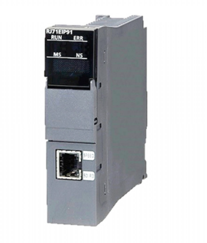 Mitsubishi RJ71EIP91 Ethernet IP Module
 -
 Siemens 3RW4047-1BB14 Soft Starter 55kW
 -
 Mitsubishi AJ71C21-A PLC Programmable Controller
 -
 NL8060BC21-06 8.4 Inch LCD Module
 -
 Siemens 6ES7215-1HG40-0XB0 PLC S7-1200
 -
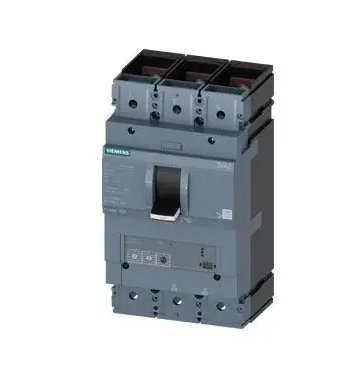 Siemens 3VA2463-5HL32-0AA0 630A Breaker
 -
 Saginomiya E-UJ-44030-B Control Board
 -
 Schmersal MV10H330-11y-M20-1348 Safety Switch
 -
 Fanuc A16B-1211-0301-04A Control Board
 -
 Siemens 6SN1123-1AB00-0AA2 LT Module
 -
 A100005506 Compair Delcos 3100 Control Panel
 -
 Omron ZFV-CA40 Smart Sensor Amplifier
 -
 Fanuc A16B-2200-0660 I O Board
 -
 Omron CJ1W-NC471 Position Control Unit
 -
 Siemens 6SN1112-1AA00-0AA0 Simodrive PWM Module
 -
 Mitsubishi GT2708 HMI Touch Panel
 -
 Siemens 3TK2834-1BB40 Safety Switch
 -
 INSYS EBW-E100 Industrial Ethernet Router
 -
 Schneider LC1F400 Contactor TeSys F
 -
 Mitsui RYP-51 PCB Control Board
 -
 Tamagawa TS2620N941E172 Encoder
 -
 Pilz PZE 9 Safety Relay
 -
 Omron C1000H-CPU01-V1 PLC
 -
 Siemens 6SL3210-1KE21-3UP1 Frequency Converter
 -
 Allen-Bradley 440E-L22BNSM Rope Pull Switch
 -
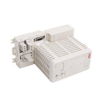 ABB CI868K01 Interface Module
 -
 Stein Sohn E 083.1 PLC Rack
 -
 Mitsubishi GT2508-VTBD GT2508-VTBA HMI
 -
 ABB 3BSE018161R1 Module
 -
 CAREL ASD100 PGD1AY0I00 Operation Panel
 -
 ABB EK370-40-11 Contactor 220-230V
 -
 Eaton 9PX1500IRTM UPS 1500VA
 -
 NCV-20NGNMP Programmable Controller
 -
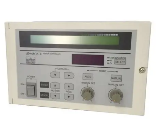 Mitsubishi LE-40MTA-E Tension Controller
 -
 Fanuc A16B-3200-0429 Control Board
 -
 Mitsubishi GT2310-VTBA HMI Touch Screen
 -
 3A99184G 1C31170G PCB Module Rev 10
 -
 Schneider 140NOM25200 Modicon Quantum Adapter
 -
 Mitsubishi NV400-SW 400A Circuit Breaker
 -
 Applied Materials 0190-51102 Heater Controller
 -
 Omron C200H-DA003 Analog Output Module
 -
 Yaskawa JANCD-YCP21-E DX200 CPU Board
 -
 IAI 12G2-60-250-P-L-C1-SP Intelligent Actuator
 -
 NLT NL8060BC21-11 8.4 LCD Screen
 -
 Omron NX502-1300 Controller Unit
 -
 ABB RVT-6 Power Factor Controller
 -
 Schneider TM258LF66DT4L PLC Controller
 -
 NLT NL6448BC26-27D 8.4 LCD Panel
 -
 NLT NL8060BC21-09 8.4 LCD Screen
 -
 Keyence XG-8700L Multi-camera Imaging System
 -
 EPC 50 3183045486 I O Motherboard
 -
 Nidec Emerson M701-054-00270A CT Drive
 -
 Therma Wave 18-011040 Controller Assembly
 -
 Mitsubishi Q03UDECPU PLC CPU Module
 -
 Allen-Bradley 2002-NX70-MWLINK PLC Module
 -
 AS-2P-60M-B Industrial PLC Cable
 -
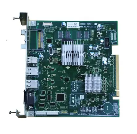 Yaskawa JANCD-YCP21-E DX200 CPU Board
 -
 PASABAN MC-2006 03 CAN PLC Card
 -
 Mitsubishi RJ71PB91V PROFIBUS DP Module
 -
 Fanuc A20B-8100-0137 PCB I O Board
 -
 D0-06DD2-D PLC Module DL06 PLC
 -
 Kepco BOP100-4M Power Supply Amplifier
 -
 Allen-Bradley 1785-L60B PLC-5 60 Module
 -
 Siemens 7MH4900-3AA01 Weighing Module
 -
 Pilz 773100 PNOZ m1p Safety Controller
 -
 Omron NS12-TS00B-V2 Graphic Operation Panel
 -
 EC20-4040BTA Programmable Controller PLC
 -
 Fanuc A16B-1212-0100-01 Power Unit CNC
 -
 Siemens 6ES7151-3BB23-0AB0 ET200S Interface Module
 -
 ATTO Control DU-01 PLC Display System
 -
 Keyence KV-RC8BXR Programmable Controller
 -
 Lenze GST04-1GVCK-063C22 Servo Motor
 -
 CKD AX9000GH AX9210H Control Unit
 -
 ABB PG6310 DC Trigger Control Board
 -
 Cutler Hammer 10316H621C Type L Device
 -
 TAIYO AA-277 EM CY TRIP PCB Card
 -
 Schneider BMXCPS2010 PLC Power Supply
 -
 Schneider TSXMRPC007M PLC PCMCIA Card
 -
 101182218 Safety Stop Relay SSW301HV-230V
 -
 Cutler Hammer 9-1875-3 Size 6 Contactor 480V
 -
 Nidec UNI3401 Drive Module Control Board
 -
 Delta AS06XA-A PLC Module Analog Mixed IO
 -
 Lenze EPL 10201 13408978 Servo Drive 24V DC
 -
 Sigmatek CCP612-K PLC Module DI DO Module
 -
 Schneider ATS48D38Q Soft Starter Altistart 48
 -
 Fanuc A20B-3300-0472 Main CPU Board Series 30i
 -
 Mitsubishi A171SCPU-S3 Servo CPU Module PLC
 -
 ABB 1SFL597001R7011 700A 100-250V Soft Starter
 -
 Yaskawa JANCD-YCP21-E DX200 CPU Control Board
 -
 Schneider NS630N Circuit Breaker 3P 630A
 -
 Honeywell DPCB21010002 Rack Slot PCB
 -
 Mitsubishi RJ71EIP91 PLC Module
 -
 Siemens 3VL5763-1DC36-0AA0 Circuit Breaker
 -
 Siemens 6GK7542-1AX00-0XE0 Communication Module
 -
 Siemens 6SL3130-6AE15-0AB1 Smart Line Module
 -
HMS Anybus AB7646-F Gateway
-
 Honeywell 621-0020 Analog Input Module
 -
 Siemens 6ES7212-1HF40-0XB0 PLC Controller
 -
 MAK 1.00.7-36.21.00-40 PCB Module
 -
 ABB 3BSE006503R1 PFSA140 Power Supply
 -
 SAACKE F-GDSA 143303 Burner Controller
 -
 ABB PFSC230 25m Cable Set
 -
 GE HYDRAN 201Ci-1 Controller
 -
 ABB NINT-42C main circuit interface board
 -
 B&R 3AT660 6 Thermocouple Input Module
 -
 Honeywell EC7850A1080 Programmable Logic Controller
 -
 Mitsubishi A2ACPU21 CPU Module MELSEC A Series


