
WAGO I/O System 750/753 Series Distributed Automation System
Applicable scenarios: Indoor dry environments in the field of industrial automation, suitable for ordinary industrial areas, and certified for special scenarios such as marine, nearshore, explosion-proof (Ex i), functional safety, etc.
Installation requirements: As an open device, it needs to be installed in an additional enclosure and operated by professional electrical personnel according to standards such as EN 50110-1/-2 and IEC 60364.
WAGO I/O System 750/753 Series Distributed Automation System
Core positioning and purpose of the system
Core function: Receive digital/analog signals from sensors, control actuators, communicate with higher-level controllers through fieldbus interfaces, and support signal preprocessing.
Applicable scenarios: Indoor dry environments in the field of industrial automation, suitable for ordinary industrial areas, and certified for special scenarios such as marine, nearshore, explosion-proof (Ex i), functional safety, etc.
Installation requirements: As an open device, it needs to be installed in an additional enclosure and operated by professional electrical personnel according to standards such as EN 50110-1/-2 and IEC 60364.
System hardware structure and characteristics
1. Classification and functions of core components
Specific classification of component types and key characteristics
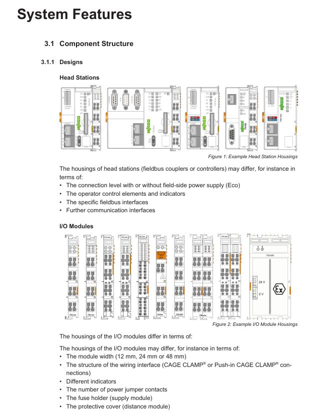
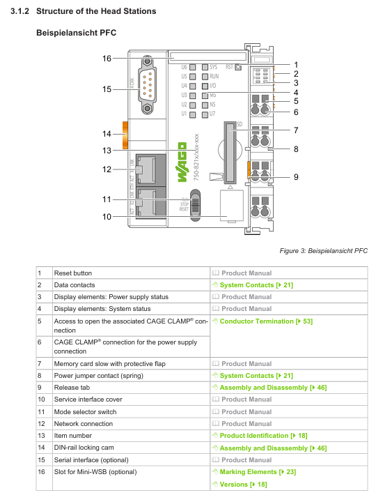
Head Stations' fieldbus couplers, controllers, and PFCs provide fieldbus interfaces (such as PROFINET and ETHERNET) to manage I/O module communication and power supply, with reset keys, status indicator lights, and service interfaces
I/O module analog input/output module supports voltage and current signal acquisition and output, distinguished by color coding (green=analog input, blue=analog output)
The digital input/output module is adapted to switch signals, with color codes of yellow (input) and red (output)
Functional/technical modules include relay module, communication module, filtering module, and transparent shell identification
The power/segment module provides system/on-site power supply, supports potential partitioning, and can interrupt or switch power supply links
The auxiliary component end module is used for node end sealing to ensure mechanical stability
Distance module (750-616) is used to increase creepage distance in explosion-proof scenarios, with a width of 12mm
2. Module physics and connection characteristics
Appearance and coding:
Types of shell color differentiation: light gray (standard module), blue (Ex i explosion-proof), signal yellow (functional safety), dark gray (750 XTR).
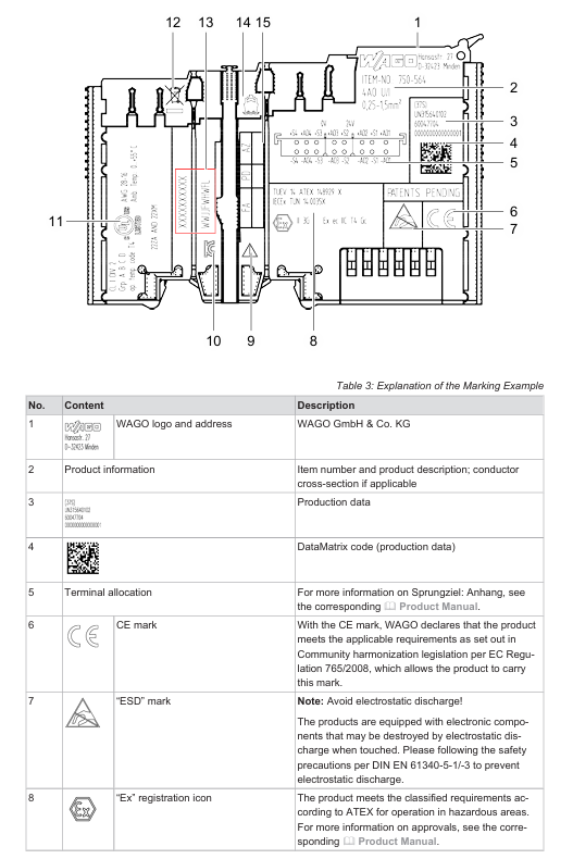
Marking information: including product model, wire cross-section, production data, DataMatrix code, CE/UL/Ex certification identification, etc. The head station serial number is marked on the service interface cover plate.
Connection technology:
CAGE CLAMP ®: It needs to be opened with operating tools and supports solid, multi strand, and thin multi strand conductors (0.08-4mm ²).
Push-in CAGE CLAMP ®: Tool free direct insertion (multi strand/thin multi strand conductors with cold pressed ends, solid conductors), other conductors require tool assistance.
Mechanical parameters:
Module width: 12mm, 24mm, 48mm, maximum node length (from head station to end module) ≤ 768mm.
Installation adaptation: 35mm DIN rail, fixed by locking cam, supports horizontal (left/right/up/down) and vertical (up/down) installation posture.
3. Electrical structure and power supply
Potential level:
System level: including system power supply (24VDC), local bus signals, and electrical isolation from other levels.
On site level: including on-site power supply (24VDC/230VAC, etc.), I/O signals, and can be divided into multiple potential zones.
Fieldbus level: independent of the first two, voltage/current depends on the fieldbus standard.
Power supply requirements:
System power supply: SELV/PELV power supply is required, and the total current of a single node should not exceed the rated value of the module. It is recommended to use the same voltage source for power supply.
On site power supply: configured according to the load, supporting different voltages in multiple areas (such as 24VDC, 230VAC), and requiring overcurrent protection (integrated fuse power module or external fuse).
Buffer requirements: When meeting the IEC 61131-2 standard, an external buffer module (such as UPS, capacitor buffer) is required.
System Planning and Installation Specification
1. Core requirements for node planning
Node composition: It should include at least one head station, one power module, one I/O module, and one end module, and support up to 250 addressable I/O modules.
Security planning:
In hazardous voltage scenarios, DIN rails must be grounded (PE) to ensure electrical connection with the enclosure/frame.
Control lines, signal lines, and power lines need to be spatially separated to avoid electromagnetic interference.
Data security: control the isolation of the network from the Internet/office network, close useless ports, change passwords regularly, and adopt the "defense in depth" mechanism.
Installation gap:
Both sides of the node should be ≥ 20mm, and the top and bottom should be ≥ 35mm (if the top is a heating component, it should be ≥ 65mm), to avoid blocking heat dissipation.
2. Installation and disassembly steps
Installation process:
Head station installation: The buckle is fixed on the DIN rail, and the locking cam is rotated with a tool to engage.
I/O module installation: Assemble from left to right in sequence, press until the buckle is locked. The 753 series requires fixing the module before connecting the wiring interface.
Encoding configuration: The 753 series module prevents accidental insertion by encoding the key (753-150), with 2 keys supporting 16 encoding combinations.
Dismantling process:
Power outage confirmation: Disconnect the system from the on-site power supply and verify that there is no voltage before operation.
Head station disassembly: Unlock the locking cam with the tool, pull the release buckle to detach from the guide rail.
I/O module disassembly: 750 series, directly pull the orange release buckle; The 753 series first separates the wiring interface (pull the locking latch), and then pull the release buckle.
3. Wiring operation specifications
Conductor requirements:
Supports copper and aluminum conductors (aluminum conductors need to be cleaned and coated with "Alu Plus" contact paste), with only one conductor connected to a single clamping unit.
The cross-sectional area of the wire needs to match the current load, and larger cross-sectional conductors should be selected in high current scenarios to reduce temperature rise.
Wiring steps:
CAGE CLAMP ®: Insert the tool into the rectangular opening to open the fixture → Insert the conductor → Pull out the tool lock.
Push-in CAGE CLAMP ®: Direct insertion adapter conductor; Non compatible conductors require tools to be tilted and inserted into the opening after opening the fixture.
Special scenario application configuration
1. Marine and nearshore scenarios (DNV certified)
Classification requirements:
Class A: Suitable for non bridge and non outdoor deck areas; Class B: Suitable for the entire area (including the bridge and outdoor deck).
Power supply configuration:
A high isolation (HI) filtering module is required for 24VDC power supply: the 750-626 series is used for system power supply, and the 750-624 series is used for on-site power supply.
Isolation monitoring scenarios require the use of HI version filtering modules (such as 750-624/020-000, 750-626/020-000).
Exception: Non 24VDC on-site power supply does not require additional filtering modules.
2. Explosion proof (Ex i) scenarios
Power supply requirements:
Only use Ex i dedicated bus power supply module (750-606 with diagnosis, 750-625/000-001 without diagnosis).
Distance requirement:
The Ex i power supply module needs to be connected in series in front of the Ex i module area, and four distance modules (750-616) need to be connected behind the area; If the subsequent module is the bus extension end module (750-627), only one distance module is required; If it is a regular end module (750-600), no distance module is required.
Operation restrictions: It is prohibited to plug or unplug components, connect wires, operate switches, or replace fuses in explosive environments.
3. Functional safety scenarios
Power supply protection:
The system and on-site power supply (24VDC) require the configuration of filtering modules (750-626 series for the system and 750-624 series for the site) to meet the surge protection requirements of EN 61326-3-1.
Module requirements: Use I/O modules with Functional Safety Identification (FS) and configure redundancy or isolation measures according to safety levels.
4. UL certification scenario requirements
Ordinary area:
The 24VDC system requires an external slow melting fuse (maximum 2A, minimum 30VDC) for power supply.
24VDC on-site power supply requires external slow melting fuses (maximum 10A, minimum 30VDC); ≤ 250VAC/DC on-site power supply fuse, maximum 10A.
Dangerous Area (Class I, Division 2):
It needs to be installed in the shell unlocked by the tool, and can only be operated after power off or confirming that there is no risk of explosion in the area.
Specific modules (such as 750-439, 750-538) are only allowed to be used in conjunction with Ex i power supply modules (750-606/750-625).
Safety and compliance requirements
1. General safety regulations
Personnel qualifications: Installation, operation, and maintenance must be carried out by professional electrical personnel who comply with EN 50110-1/-2 and IEC 60364 standards.
Electrical safety:
Disconnect all power supplies before operation and verify that there is no voltage; SELV/PELV circuits need to be safely isolated from hazardous voltage circuits.
To avoid electrostatic discharge (ESD), take protective measures according to DIN EN 61340-5-1/-3 (such as anti-static wristbands).
Mechanical and thermal safety:
Do not open the product casing and avoid touching live contacts; The shell may generate heat and needs to be cooled before touching in high temperature environments.
Do not use cleaning agents that contain penetrant/insulating properties (such as silicone, glycerin). Isopropanol can be used for cleaning.
2. Certification and Compliance
International certifications: including CSA, KEMA/KEUR, ABS (Classification Society), UL, ATEX, EAC, CCC, RCM and other certifications.
Following standards: EN 60947, UL 1059, IEC 61010-1, WEEE (Waste Disposal), etc.
Intellectual Property: The content of the document is protected by copyright and may not be copied or distributed without written permission from WAGO; Third party trademarks and patents belong to the corresponding party.
3. Disposal and Recycling
Disposal requirements: Classify and recycle electrical and electronic waste according to local regulations, and do not mix it with household waste.
Preprocessing: Remove memory cards and batteries (such as lithium batteries and lead-acid batteries), clear stored data, and operate with protective equipment.
Packaging recycling: B2B transportation packaging can be recycled for free through the Interseroh system.
Supporting tools and accessories
1. Configuration and debugging tools
COCKPIT: integrates hardware configuration, programming, simulation, visualization, and debugging functions, supporting fully automated processes.
WAGO Smart Designer: 3D configuration tool that can design node structures and calculate power requirements.
WAGO-I/O-CHECK: Used for testing 750/753/XTR series nodes, supporting input/output control and status monitoring.
2. Essential Attachment List
Attachment Type Model Example Function
DIN rail 210-1xx series steel/copper material, 35mm specification, galvanized/chrome plated treatment
Operating tool 210-722 insulated handle, compatible with CAGE CLAMP ® wiring
Test probes 735-500, 859-500 1mm diameter, supporting 30VAC/60VDC, CAT0 level
Code key 753-150 753 series module anti misplacement, providing 16 different codes
Marking part 2009-145 Mini WSB Inline marking, roll up 1500 pieces, stretchable 5-5.2mm
End block 249-1xx series screw free end block, compatible with 35mm DIN rail
Shielding connection system 790 series enhances cable shielding grounding effect and reduces electromagnetic interference
Buffer module 787 series capacitor buffer ensures power supply stability
- OMRON
- ABB
- General Electric
- EMERSON
- Honeywell
- HIMA
- ALSTOM
- Rolls-Royce
- MOTOROLA
- Rockwell
- Siemens
- Woodward
- YOKOGAWA
- FOXBORO
- KOLLMORGEN
- MOOG
- KB
- YAMAHA
- BENDER
- TEKTRONIX
- Westinghouse
- AMAT
- AB
- XYCOM
- Yaskawa
- B&R
- Schneider
- KONGSBERG
- NI
- WATLOW
- ProSoft
- SEW
- ADVANCED
- Reliance
- TRICONEX
- METSO
- MAN
- Advantest
- STUDER
- DANAHER MOTION
- Bently
- Galil
- EATON
- MOLEX
- DEIF
- B&W
- ZYGO
- Aerotech
- DANFOSS
- Beijer
- Moxa
- Rexroth
- Johnson
- WAGO
- TOSHIBA
- BMCM
- SMC
- HITACHI
- HIRSCHMANN
- Application field
- XP POWER
- CTI
- TRICON
- STOBER
- Thinklogical
- Horner Automation
- Meggitt
- Fanuc
- Baldor
- SHINKAWA
- Other Brands
- UniOP
- KUKA
- Iba
- Beckhoff
-
 Basler DECS-200-2L Digital Excitation Control
 -
 Basler BE1-47N Voltage Phase Sequence Relay
 -
 Basler AEC63-7 Analog Excitation Controller 220-277V
 -
 Basler BE1-50/51B-107 Overcurrent Relay
 -
 Basler Electric BE1‑32R BE1‑E1P‑BON0F Protective Relay
 -
 Basler BE1-25 Solid State Time Overcurrent Relay M1EA6PA5S1F
 -
 Basler MVC 232 Manual Voltage Control Module 90 37000 103 60VAC 55VDC
 -
 Basler RAL6144-16GM Racer GigE Line Scan Camera
 -
 Basler SSR 63-12 Static Voltage Regulator
 -
 Basler BE1-51A Overcurrent Relay
 -
 Basler BE1-87T Solid State Protective Relay
 -
 Basler SR4A2B01B3A Static Voltage Regulator
 -
 Basler SSR 32-12 Static Voltage Regulator
 -
 Basler TRR00696 Transformer 1KVA 115V
 -
 Basler DECS-100-B15 AVR Replacement
 -
Basler BE1-27 Under-Voltage Relay
-
 Basler ACA2000-50GM Interface Module
 -
 Basler AEC63-7 Analog Excitation Controller
 -
 Basler PRS 250 Veri-Sync Relay
 -
 Basler SR4A-2B15B3A Static Voltage Regulator
 -
Basler BE1-32R Power Relay
-
Basler SR8A-2B06B3E Static Voltage Regulator
-
Basler BE1-81 O/U Frequency Relay
-
 Basler BE1-51A-K2E-W6M-B1N0F Overcurrent Relay
 -
Basler BE1-851 Overcurrent Relay G3A1S1 – 48-125V AC/DC
-
 Basler BEI-51 Overcurrent Relay – NSN 5945-01-293-2363
 -
Basler Electric L301KC Protective Relay – L301KC
-
 Basler DECS-100-B15 Automatic Voltage Regulator – Generator AVR
 -
 Basler SR4A-2B15B3A Static Voltage Regulator – SR4A2B15B3A
 -
 Basler UF 312 Under Frequency Protective Module – 9094700100
 -
Basler Electric MVC 232 Manual Control Module – 60VAC 55VDC 20A
-
Basler PRS 250 Veri-Sync Relay – Generator Synchronizing Relay
-
 Basler DECS-100-A05 Digital Regulator Review
 -
 Basler AEM-2020 Analog Expansion Module Specs
 -
 Basler DECS-100-B15 Digital Excitation Specs
 -
Basler Electric 9125600106 Regulator Component
-
Basler BE1-51A-K1E-W6M-B1N0F Overcurrent Relay
-
 Basler MVC-301 MVC 300 Excitation Controller
 -
 Basler SSR 32-12 Static Voltage Regulator
 -
 Basler 9-2849-00-101 Control Module
 -
Basler BE1-51A Overcurrent Relay
-
 Basler BE1-51/27R Overcurrent Relay
 -
 Basler BE1-51 Overcurrent Relay
 -
 Basler SR8A-2B15B3A Static Voltage Regulator
 -
 Basler BE32965001 Transformer and Timer Board
 -
 Basler 9174700100 EL200-7 Excitation Limiter
 -
 Basler BE2000E AVR Voltage Regulator
 -
Basler BE1-87G Differential Relay
-
 Basler BE21834001 Generator Control Module
 -
Basler DECS-100-B15 AVR
-
 Basler D90 96801 100 PCB Card
 -
 Basler XR2002F Voltage Regulator (110 VAC, 48-480 Hz)
 -
 Basler SR8A-2B14B3A Regulator
 -
 Basler 9561500100 Module
 -
 Basler DECS-400 BE1-11 System
 -
 Basler DECS-100-B15 Excitation Control
 -
 Basler SCP 210 Frequency Controller
 -
Basler SR4A-2B15B3A Static Voltage Regulator
-
Basler BE1-32R Power Relay
-
 Basler PIA2400-17GM Power Interface Adapter
 -
 Basler MVC 232 Manual Voltage Control Module
 -
 Basler SSR 32-12 Static Voltage Regulator
 -
Basler 5MW AVR Generator Voltage Regulator
-
 Basler VR63-4B Voltage Regulator
 -
Basler DECS-100-A05 AVR for Engine Generator
-
Basler DECS-100-B15 Automatic Voltage Regulator
-
Basler BE1-32R Directional Power Relay
-
Basler BE1-87B Differential Relay
-
 Basler UFOV 260A Protective Module
 -
 Basler 9-2614-02-100 PCB Rev M
 -
Basler DECS-100-B15 Digital AVR
-
 Basler 9284900103 PS DECS-400N
 -
 Basler D4N3H1U Intertie Protection
 -
 Basler DECS-100-B15 A15 AVR
 -
 Basler KR4F Voltage Regulator
 -
 Basler BE26434 T14 Transformer
 -
 Basler SR8A-2B15B3A Regulator
 -
 Westinghouse 774B472A12 AR Relay
 -
Basler DECS-100-B15 AVR
-
Basler XR2002F Regulator 110V
-
Basler SR125-E Static Regulator
-
Basler SSR 125-12 Regulator
-
Basler MOC2599 Motor Pot
-
 Basler BE1-DFPR Feeder Relay
 -
 Basler CBS 305 Current Boost
 -
Basler BE1-25 AutoSync
-
Basler MVC 300 Voltage Control
-
 Basler BE3-25A AutoSync
 -
 Basler KR7FF Static Regulator
 -
Basler 90-49000-100 Regulator
-
 Basler 880 kVA Dry Type Transformer Specs
 -
Basler Electric BE1-25 Sync-Check Relay Specs
-
 Basler SSR 125-12 Voltage Regulator Specs
 -
 Basler Electric BE1-851 Overcurrent Relay Review
 -
Basler Electric 149D930G02 Control Sub-Assembly
-
 Basler Electric BE1-81O/UT Frequency Relay Specs
 -
 Basler Electric BE1-51/27C Overcurrent Relay
 -
 Basler Electric 149D956G02 Industrial Component
 -
Basler Electric BE1-51A Overcurrent Relay Specs
-
 Basler Electric BE1-40Q Loss of Excitation Relay
 -
Basler DECS-200 Excitation Control System
-
 Basler DECS-200 Voltage Regulator 56-277V AC / 125V DC
 -
Basler BE1-87T Transformer Differential Relay
-
 Basler RDP-110-S1 Protection Relay
 -
 Basler BE1-700V Digital Protective Relay
 -
 Basler BE1-951 Overcurrent Protection System
 -
 Basler DECS-300 Digital Excitation Control
 -
 Basler DECS-200 Digital Excitation Control
 -
 Basler DECS-200-1C Excitation Control System
 -
Basler DECS-200-1L Digital Excitation Control
-
 Basler Electric BE1-GPS Generator Protection System
 -
Basler Electric DECS-200-1C Digital Excitation Controller
-
 Basler Electric DECS125-15 Excitation Control with Power Module
 -
Basler Electric BE1-87G Differential Relay
-
 Basler Electric BE1-11 Protection System I5A3M2P2N0EA00
 -
Basler Electric DECS-200-1C Excitation Control System
-
Basler Electric BE1-11g Generator Protection Relay
-
Basler Electric DECS 125-15-B2C1 V2.0.9 Excitation Control
-
Basler Electric BE1-81O/UT3ED1JA7N2F Frequency Relay
-
Basler Electric BE1-81O/UT3EE1YB7N1F Frequency Relay
-
 Basler Electric DECS-200-1L Digital Excitation Control System
 -
Basler DECS125-15-B2C1 Excitation Control
-
 Basler 9507900205 SSR Retrofit Voltage Regulator
 -
 Basler BE2000E Digital Voltage Regulator
 -
 Basler BE1-GPS Generator Protection System
 -
Basler DECS-250-CN1CN1N Digital Excitation Control
-
 Basler DGC-2020 Genset Controller
 -
Basler BE1-81O UT3ED1LA7N0F Frequency Relay (Variant)


