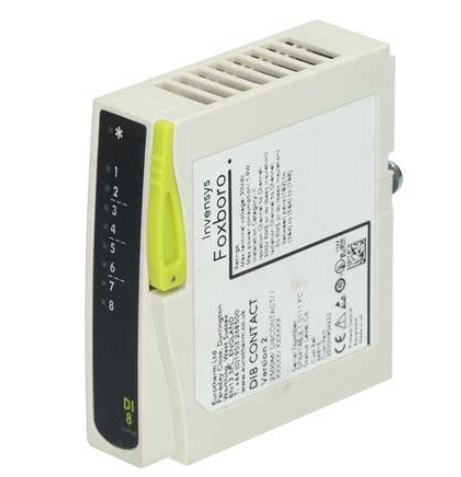
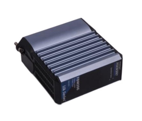
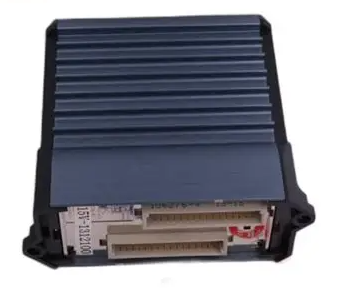
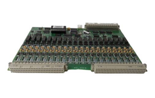
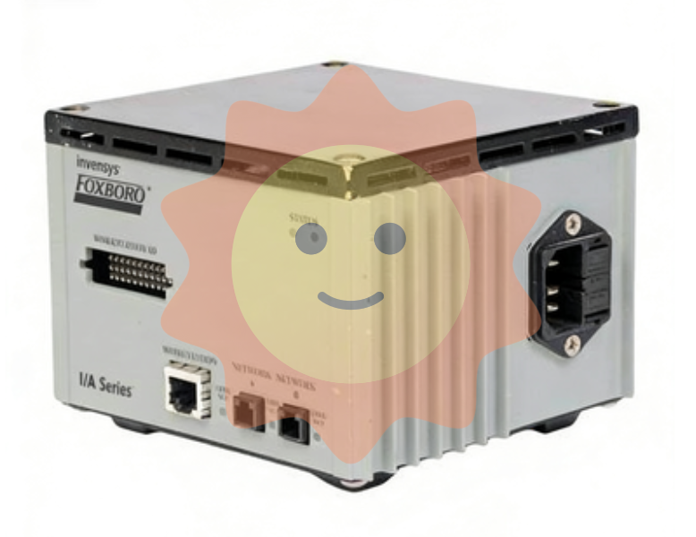
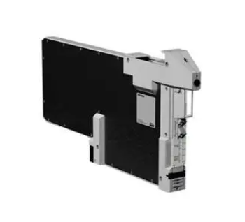
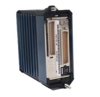
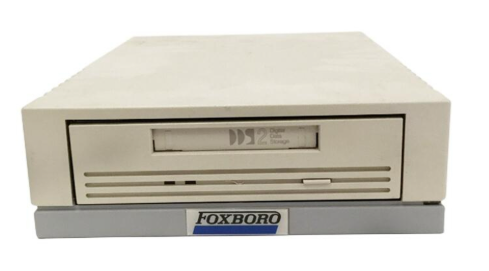
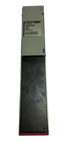
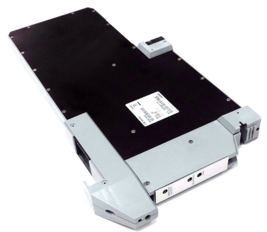
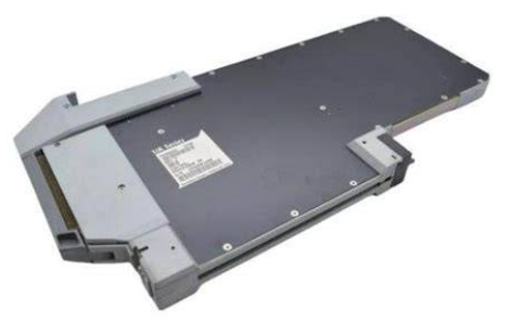
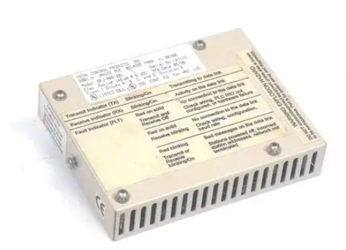
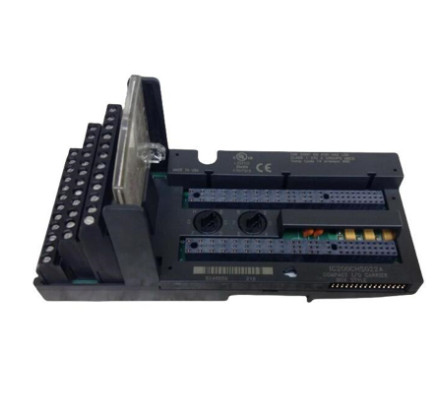
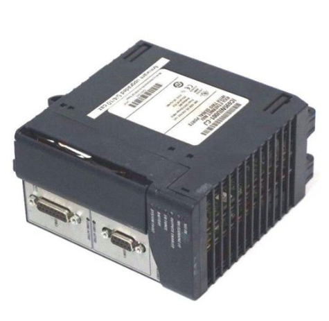
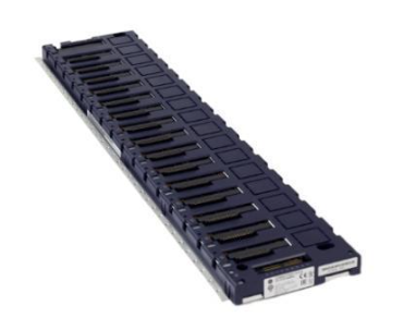
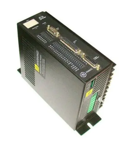
Fanuc A16B-3200-0110 CNC System Module
Fanuc A16B-3200-0110 CNC System Module
Core positioning and basic product information
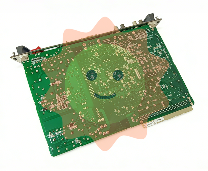
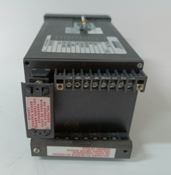
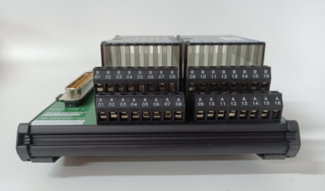
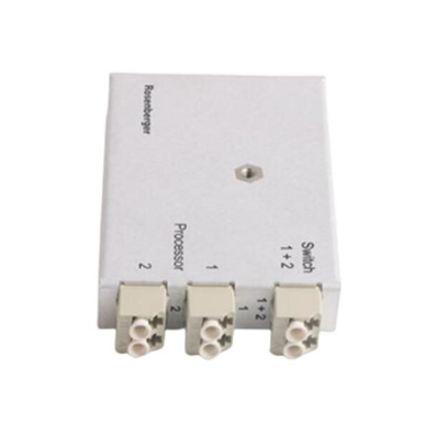
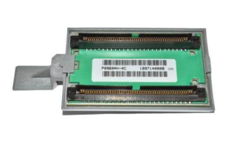
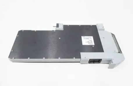
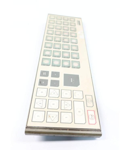
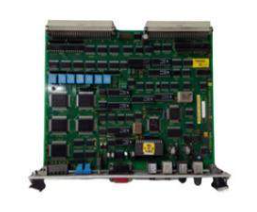
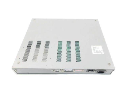
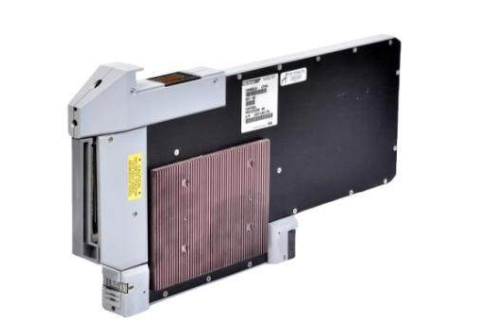
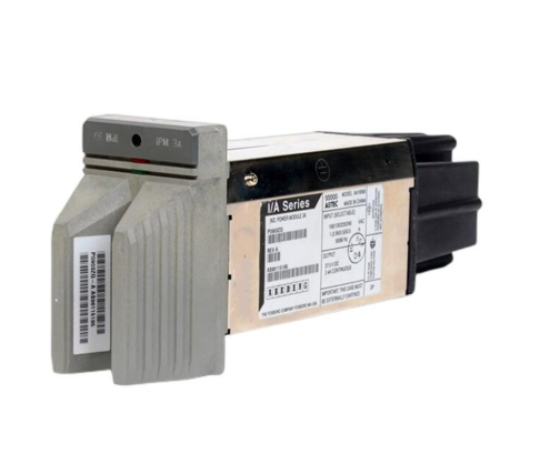
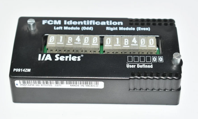
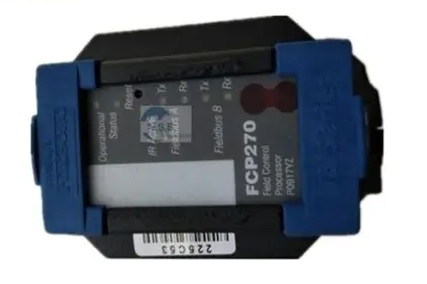
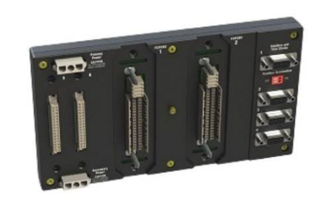
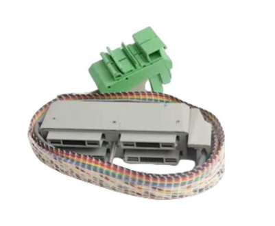
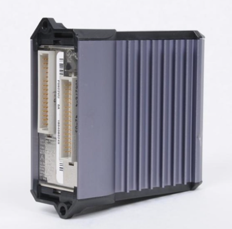
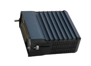
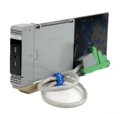
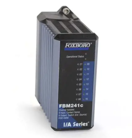
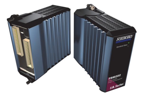
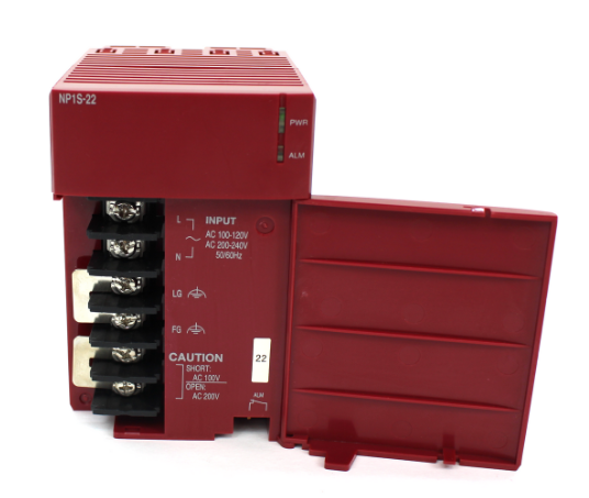
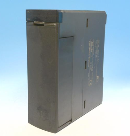
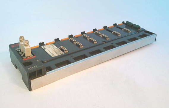
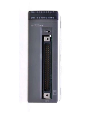
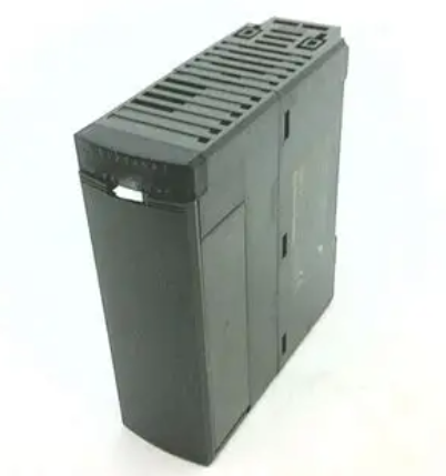
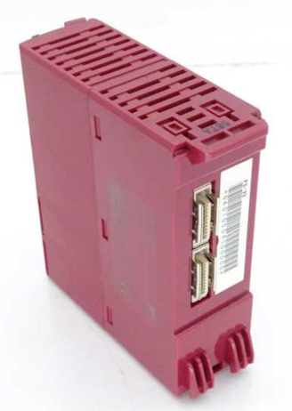
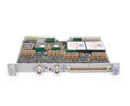
A16B-3200-0110 is a power/signal interface module designed by Fanuc specifically for CNC systems (such as 0i series, 18i series and other high-end CNC systems). Its core function is to provide stable power distribution for CNC systems, signal interaction interfaces for external devices (such as servo drives, spindle drives, operation panels), and system operation status monitoring. It is the "signal hub" for CNC equipment (such as machining centers, lathes, milling machines) to achieve precise motion control. The basic information is as follows:
Product identification:
Product model: A16B-3200-0110 (Fanuc standard model name, "A16B" is the module series prefix, "3200" is the functional classification code, and "0110" is the specific model suffix);
Product types: CNC System Module, Power/Signal Interface Unit;
Core attribute: Industrial grade CNC specialized module, non general electrical component, required to be used in conjunction with Fanuc specific CNC system.
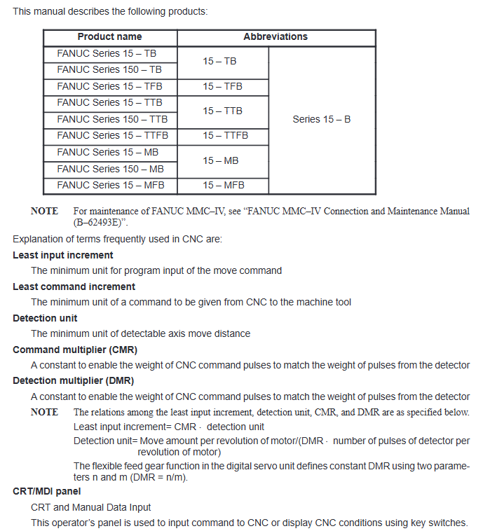
Key technologies and physical specifications
(1) Physical dimensions and weight
Specification category parameter value description
The horizontal dimension of the product length along the installation direction is approximately 240 mm, suitable for the installation slot of standard CNC system cabinets
The product has a vertical height of approximately 120mm and is compatible with Fanuc system modular stacking layout
The product width (depth) is approximately 180 mm, including the depth of the protruding part of the connector, and internal wiring space needs to be reserved in the cabinet
The net weight of the product is approximately 0.8 kg, excluding the net weight of packaged modules. The lightweight design facilitates the disassembly and assembly of modules inside the cabinet
(2) Electrical and functional parameters
Power input:
Main power supply: DC 24V (allowable fluctuation range ± 10%, i.e. 21.6V-26.4V), suitable for CNC system dedicated switching power supply;
Power consumption: Typical working power consumption is ≤ 15W (about 5W when unloaded, not exceeding 18W when fully loaded), to avoid power overload;
Signal interface:
Digital input (DI): 8-channel dry contact input, supporting 24V DC signal, used to receive external device status signals (such as emergency stop, limit switch);
Digital output (DO): 6-way relay output, contact capacity AC 250V/2A or DC 30V/2A, used to control external actuators (such as indicator lights, solenoid valves);
Communication interface: 1 RS485 interface (baud rate 9600-115200bps configurable), used for data exchange with servo drives and spindle drives;
Protection function:
Overcurrent protection: Built in power circuit overcurrent protection (threshold 1A), automatically cuts off the power supply when the module current exceeds the threshold to prevent burnout;
Overvoltage protection: When the input voltage exceeds 28V DC, the protection is triggered to prevent high voltage from damaging the internal circuit;
Anti interference: Complies with industrial grade electromagnetic compatibility (EMC) design, supports ± 15kV electrostatic discharge (ESD) protection, and adapts to strong electromagnetic environments of CNC equipment.
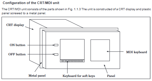
Environmental compliance and applicable conditions
Specific description of compliance category
Environmental compliance complies with the EU RoHS Directive (2011/65/EU), restricting the use of harmful substances such as lead, mercury, cadmium, etc., and meeting the environmental requirements of major global markets
Working environment - temperature: 0 ℃ -55 ℃ (no condensation, exceeding the range may cause module crash or performance degradation);
-Humidity: 5% -95% RH (non condensing, high humidity environment requires cabinet dehumidification device);
-Vibration: Within the frequency range of 5-500Hz, acceleration ≤ 5m/S ² (0.5g), avoid installing near the vibration source (such as next to an unstressed spindle motor)
Protection level IP20 (module body protection, needs to be installed in a closed CNC system cabinet, cannot be directly exposed to dust and oil pollution environment)
System adaptability and application scenarios
(1) Adapt to Fanuc CNC system
This module is only compatible with Fanuc specific series CNC systems and cannot be used across brands or series. The specific compatible models are as follows:
Mainstream adaptation systems: Fanuc 0i MF/0i TF (for machining centers/lathes), 18i MB/18i TB, 21i MB/21i TB;
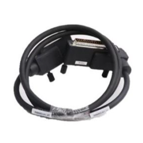
Adaptive driver: It needs to be paired with Fanuc α i series servo drivers (such as A06B-6117-H106) and α i series spindle drivers (such as A06B-6134-H303), and connected to the signal and power supply through dedicated cables.
(2) Typical application scenarios
Numerical Control Machining Equipment: As the core interface module of the CNC system for machining centers, vertical lathes, and horizontal milling machines, it realizes a signal loop of "system driver actuator" to ensure accurate positioning (such as positioning accuracy ± 0.001mm) and motion control (such as feed rate 0-10000mm/min) of the equipment;
Equipment status monitoring: Collect emergency stop, travel limit, door lock and other signals through digital input interface, provide real-time feedback on equipment safety status, and cut off the power supply of the driver through digital output interface when triggering abnormalities to ensure operational safety;
Production line integration: In automated production lines, communication with PLCs (such as Fanuc PMC) through RS485 interfaces enables collaborative work between CNC equipment and other equipment on the production line (such as cutting robots).
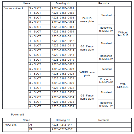
Key points for installation and maintenance
Installation requirements:
It needs to be installed in the designated slot of the Fanuc standard CNC system cabinet and fixed with screws to ensure good grounding between the module and the cabinet (grounding resistance ≤ 1 Ω);
Wiring must strictly follow the module terminal definition diagram (terminal table attached in the document), and the positive and negative poles of the power supply must not be reversed. Digital input/output signals should distinguish between dry/wet contact types to avoid module damage caused by incorrect connections;
Maintenance precautions:
Regularly check module heat dissipation (modules without fans rely on natural heat dissipation, and the ventilation inside the cabinet needs to be good to avoid temperatures exceeding 55 ℃);
If the module indicator lights (such as power lights, communication lights) are abnormal (such as power lights flashing, communication lights turning off), it is necessary to first check the power supply and cables, and then determine whether the module is faulty;
When replacing a module, it is necessary to record the parameters of the original module (such as communication baud rate and output contact configuration), and reconfigure the parameters of the new module to ensure compatibility with the system.
- EMERSON
- Honeywell
- CTI
- Rolls-Royce
- General Electric
- Woodward
- Yaskawa
- xYCOM
- Motorola
- Siemens
- Rockwell
- ABB
- B&R
- HIMA
- Construction site
- electricity
- Automobile market
- PLC
- DCS
- Motor drivers
- VSD
- Implications
- cement
- CO2
- CEM
- methane
- Artificial intelligence
- Titanic
- Solar energy
- Hydrogen fuel cell
- Hydrogen and fuel cells
- Hydrogen and oxygen fuel cells
- tyre
- Chemical fiber
- dynamo
- corpuscle
- Pulp and paper
- printing
- fossil
- FANUC
- Food and beverage
- Life science
- Sewage treatment
- Personal care
- electricity
- boats
- infrastructure
- Automobile industry
- metallurgy
- Nuclear power generation
- Geothermal power generation
- Water and wastewater
- Infrastructure construction
- Mine hazard
- steel
- papermaking
- Natural gas industry
- Infrastructure construction
- Power and energy
- Rubber and plastic
- Renewable energy
- pharmacy
- mining
- Plastic industry
- Schneider
- Kongsberg
- NI
- Wind energy
- International petroleum
- International new energy network
- gas
- WATLOW
- ProSoft
- SEW
- wind
- ADVANCED
- Reliance
- YOKOGAWA
- TRICONEX
- FOXBORO
- METSO
- MAN
- Advantest
- ADVANCED
- ALSTOM
- Control Wave
- AB
- AMAT
- STUDER
- KONGSBERG
- MOTOROLA
- DANAHER MOTION
- Bently
- Galil
- EATON
- MOLEX
- Triconex
- DEIF
- B&W
- ZYGO
- Aerotech
- DANFOSS
- KOLLMORGEN
- Beijer
- Endress+Hauser
- MOOG
- KB
- Moxa
- Rexroth
- YAMAHA
- Johnson
- Westinghouse
- WAGO
- TOSHIBA
- TEKTRONIX


Email:wang@kongjiangauto.com

