
YOKOGAWA ADMAG TI Series AXW Electromagnetic Flow Meter (25-450mm) Installation and Operation
Grounding requirements: The protective grounding resistance should be ≤ 100 Ω (Class D), and the lightning protection requirement should be ≤ 10 Ω (Class C); Metal pipelines should be connected to sensor flanges through grounding rings or grounding wires first, while plastic pipelines must use grounding rings.
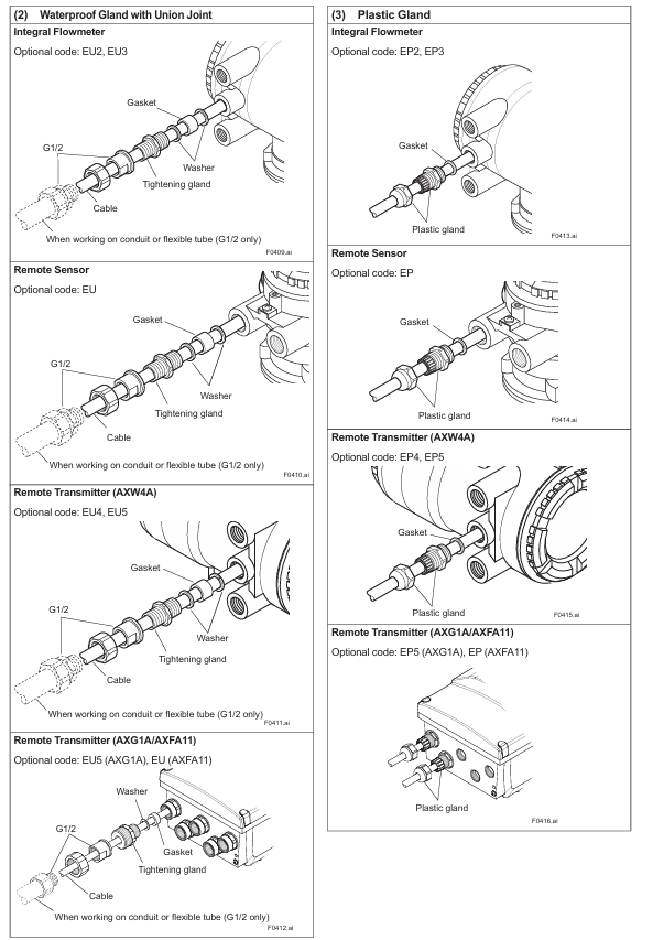
(2) Remote transmitter installation
Installation location: Avoid direct sunlight and ensure that the environment meets temperature/humidity requirements; AXW4A can be installed vertically/horizontally on 2-inch pipes, while AXG1A/AXFA11G supports surface mounting, 2-inch pipe mounting, and panel mounting (must meet load-bearing requirements: AXG1A 3.5kg, AXFA11G 3.4kg, and the bracket needs to withstand 4 times the weight).
Direction adjustment: The cable entry direction (non submersible/DHC type) can be rotated by -90 °/+90 °/+180 °, and the display screen direction can be rotated clockwise by 90 ° (the cover plate needs to be removed, pay attention to protecting the threads and O-ring).
3. Gasket selection and size
Core requirement: The inner and outer diameters of the gasket must not extend into the pipeline to avoid fluid leakage or affect measurement; Different linings (such as natural hard rubber, PTFE, polyurethane rubber) need to be matched with corresponding hardness gaskets (such as non asbestos gaskets, PTFE coated gaskets), with thickness reference to Tables 3.3.1/3.3.4.
Size inquiry: The user's pipeline gasket size should refer to Table 3.3.8, specifying the effective sealing inner diameter (ø A) and recommended gasket inner diameter (ø C/ø D) corresponding to different linings and connection types (wafer/flange).
Wiring specifications
1. Preparation before wiring
Cable requirements:
Excitation/power/IO cables: JIS C 3401 control cables and JIS C 3312 power cables are recommended, with a wire diameter of 0.5~2.5mm ² (single strand)/0.5~1.5mm ² (multiple strands), and the outer diameter needs to match the cable sealing sleeve (such as waterproof sealing sleeve compatible with 7.5~12mm).
Special signal cable (AX01C): Double shielded structure, with a maximum length of 200m when paired with AXG1A/AXFA11 and 100m when paired with AXW4A. Cutting or splicing is prohibited, and excess length must be cut off.
Protective measures: When the ambient temperature is above 50 ℃, cables with a temperature resistance of 70 ℃ or above are required; Power and signal cables need to be separately threaded through steel conduits (excluding 24V power supply and 4-core cables); Explosion proof wiring must comply with the corresponding explosion-proof standards.
2. Wiring operation
Power wiring: DC power supply should pay attention to the positive and negative poles (L/+connected to the positive pole, N/- connected to the negative pole), and 24V models should not be connected to 100-240V power supply; 15A external switch/circuit breaker needs to be installed and labeled as "power-off equipment".
Grounding Wiring: The protective grounding wire requires a 600V ethylene insulated cable, and the terminals require circular crimping terminals (M4 screws) with insulation covers to ensure reliable connection; Remote type requires separate grounding sensors and transmitters.
Cable entrance sealing: Unused entrances need to be sealed with dedicated plugs, waterproof sealing sleeves need to be evenly tightened (to avoid damaging the cable due to over tightening), and vertical conduits need to be equipped with drainage valves at the low end and regularly drained.
3. Communication and IO wiring
Communication protocol wiring: Modbus requires 3-core shielded wire (AWG24 or above), FOUNDATION Fieldbus/PROFIBUS PA requires Type A cable, EtherNet/IP requires CAT5e or above shielded twisted pair (without protective cover).
IO signal wiring: current output (4-20mA), pulse output (maximum 10000 pulses/second), status input (no voltage contacts), etc. need to be wired according to the terminal configuration table (such as 4.4.4/4.5.2) to ensure galvanic isolation (input/output/power circuits are isolated from each other).
Basic operations and parameter settings
1. Operation method
Display screen operation: Operated through three infrared (IR) buttons ([SET], [SHIFT], [▼]), supporting parameter viewing/modification, zero point adjustment, etc; The default display language is English, which can be switched through "Device setup ► Language" (supports multiple languages such as Chinese, French, German, etc., depending on the display code).
Operation level: divided into three levels: Operator (no password required, only basic display settings), Maintenance (maintenance personnel, password required, including zero adjustment), Specialist (expert, password required, full parameter settings), default password "0000".
2. Key operational procedures
(1) Mode switching: Display mode → Set mode
Long press [SET] for a few seconds, touch [FFT]+[INC];
Select "Yes" with [INC], double-click [SET] to confirm;
Select the operation level, enter the corresponding password (Maintenance/Specialist requires password), and enter the "Device setup" menu.
- OMRON
- ABB
- General Electric
- EMERSON
- Honeywell
- HIMA
- ALSTOM
- Rolls-Royce
- MOTOROLA
- Rockwell
- Siemens
- Woodward
- YOKOGAWA
- FOXBORO
- KOLLMORGEN
- MOOG
- KB
- YAMAHA
- BENDER
- TEKTRONIX
- Westinghouse
- AMAT
- AB
- XYCOM
- Yaskawa
- B&R
- Schneider
- KONGSBERG
- NI
- WATLOW
- ProSoft
- SEW
- ADVANCED
- Reliance
- TRICONEX
- METSO
- MAN
- Advantest
- STUDER
- DANAHER MOTION
- Bently
- Galil
- EATON
- MOLEX
- DEIF
- B&W
- ZYGO
- Aerotech
- DANFOSS
- Beijer
- Moxa
- Rexroth
- Johnson
- WAGO
- TOSHIBA
- BMCM
- SMC
- HITACHI
- HIRSCHMANN
- Application field
- XP POWER
- CTI
- TRICON
- STOBER
- Thinklogical
- Horner Automation
- Meggitt
- Fanuc
- Baldor
- SHINKAWA
- Other Brands
- UniOP
- KUKA
- Iba
- Beckhoff
-
 Basler BE1-57/27R Solid State Protective Relay
 -
 Basler BE3-25AX Time Overcurrent Relay
 -
 BASLER ELECTRIC BE1-24/A1EF1JC1N0F / BE124A1EF1JC1N0F Overvoltage Relay
 -
Basler Electric Solid State Protective Relay BE1-32R Style B2ED1PB0N0F
-
 Basler BE3-51-3E1E1 9320000110 24VDC Overcurrent Relay
 -
 Basler UFOV 260A Underfrequency Overvoltage Module
 -
 Basler 50F4EA1PA0N0F Instantaneous Overcurrent Relay
 -
 Basler BE1-50 Instantaneous Overcurrent Relay
 -
 Basler BE1-32 Solid State Protective Relay
 -
 Basler SCP 250-G-60 VAR Power Factor Controller
 -
Basler BE1-59N A5EE1KC0N0F Ground Fault Relay
-
Basler BE1-79A Reclosing Relay
-
Basler BE1-32R E1EA1OA0N0F Reverse Power Relay
-
 Basler DCQA-103 DCQC104-1 CMX-7D Circuit Board
 -
 Basler SSR125-12 Static Regulator 918500102
 -
 Basler 90 17709 112 Regulator Control Board
 -
 Basler AVC63-4 AVC634 Voltage Regulator
 -
 Basler 9 1049 04 100 PC Board Control Module
 -
 Basler SR4A-2B03B3A Static Voltage Regulator
 -
 Basler SR8A-2B15B3A Static Voltage Regulator
 -
 Basler KR7FFX Static Regulator 840V
 -
 Basler EL200-7 Voltage Regulator 90-660VAC 7A
 -
 Basler PRP210-1 Reverse Power Relay 9056300102
 -
 Basler SSR 63-12 Static Regulator 600VAC
 -
 Basler 9289901106 Digital Board
 -
Basler DECS100 Voltage Regulator DECS100A01
-
 Basler Electric CEM-2020 Contact Expansion Module
 -
Basler Electric BE3-25-1 C1 N4 Synchronizing Check Relay
-
 Basler Electric ACA2000-50GM GigE Camera 2MP 50fps
 -
 Basler Electric ACA2240-20GMSYM GigE Camera Sony IMX264
 -
 Basler BE1-50G Ground Overcurrent Relay
 -
 Basler PRS250 Veri-Sync Relay
 -
Basler MOC2199 Output Module
-
 Basler UFOV 260A Underfrequency Overvoltage Module
 -
 Basler BE-15482-001 Control Module
 -
Basler LSP4-7 Protective Relay
-
 Basler SCP 250-G-60 VAR Power Factor Controller
 -
Basler BE146N Negative Sequence Overcurrent Relay
-
Basler APR63-5 Automatic Voltage Regulator
-
Basler 9507900107 SR8A Retrofit Voltage Regulator
-
Basler BE1-320 Directional Power Relay
-
 Basler KR7F Voltage Regulator 9116200100
 -
Basler UFOV 260A Overvoltage Protective Module
-
 Basler AEC63-7 Analog Excitation Controller
 -
Basler 9992D90G01 Control Module
-
 Basler 6966D22G01 Control Board
 -
Basler 6965D40G01 Control Board
-
 Basler BE1-50/51M-104 Overcurrent Relay
 -
 Basler BE1-BPR Programmable Breaker Relay
 -
 BASLER Electric SSR 125-9 1256 00 102 Static Voltage Regulator
 -
 Basler Electric MVC 112 Manual Voltage Control
 -
 Basler Electric 9321000102 Control Module
 -
 Basler Electric RA-70-MDCT7 Rectifier Assembly
 -
 Basler Electric ACA1300-60GM GigE Camera
 -
 Basler Electric 6427C85G01 Interface Board
 -
Basler Electric 6965D05G01 Control Board
-
Basler Electric ACA2500-14UC Current Transducer
-
 Basler Electric 9170206111 Protective Relay
 -
 Basler Electric BE1-11-G6D1M1J1P0E000 Protection Relay
 -
Basler Electric BE1-50/51B-107 Overcurrent Relay
-
 Basler 9121000106 Voltage Controller
 -
 Basler B3E-E1P-A0N0F Solid State Protective Relay
 -
 Basler 9121000106 Manual Voltage Control
 -
Basler PRP320 Motor Pull-out Relay
-
 Basler SSE-N 250-9KW Shunt Exciter Regulator
 -
 Basler BE1-50-51B-107 Overcurrent Relay
 -
 BASLER ELECTRIC MVC 108 MANUAL VOLTAGE CONTROL MODULE 9 0370 00 102
 -
Basler BE1-59N-A7E-D1J-D0N0F Ground Overvoltage Relay
-
Basler BE1-46N-G1E-B8P-B0N0F Negative Sequence Overcurrent Relay
-
Basler BE1-951 Overcurrent Protection System
-
 Basler Electric MOC2199 Motor Operated Potentiometer
 -
 Basler Electric BE1-60 Voltage Balance Solid State Relay B1FA1C1M1F
 -
Basler Electric BE1-67N Directional Overcurrent Relay
-
Basler Electric PIA2400-17GM Interface Module
-
 Basler Electric V6RAB Rectifier Module
 -
Basler Electric BE1-32R Reverse Power Relay B2E E1R A0N1F
-
Basler Electric IFM-150 Firing Circuit Chassis 120V AC
-
 Basler Electric IFM-102 Firing Circuit Chassis 120V AC
 -
 Basler Electric 9170206111 NSNP Control Module
 -
Basler Electric SSR 63-12 Static Voltage Regulator
-
 Basler UFOV 260A Overvoltage Protective Module
 -
Basler SCA1300-32GM CCD Camera Lens Enclosure
-
 Basler BA1-27 Under Voltage Relay
 -
Basler 149D866G06 Control Board
-
 Basler 9072300130 Power Supply Module
 -
Basler CBS 305 Current Boost System
-
 Basler BE1-60 Voltage Balance Relay
 -
 Basler Electric CBS 212 Current Boost System Sensing 120/240VAC 50/60Hz 10VA
 -
 Basler MVC-300 Manual Voltage Control Unit
 -
Basler SSR125-12 Static Voltage Regulator 918500102
-
Basler SR32A2B05B3E Static Voltage Regulator
-
Basler Electric BE1-59N Ground Fault Overvoltage Relay
-
 Basler Electric 9110000113 Excitation Module
 -
Basler Electric 90-72300-114 Control Accessory
-
Basler Electric PRS-250 Protection Relay System
-
Basler Electric BE1-50/51M-109 Overcurrent Relay
-
 Basler Electric SR4A1B10B3E Static Voltage Regulator
 -
 Basler Electric CBS 212 Current Boost System
 -
Basler Electric SR32A2B05B3E Static Voltage Regulator
-
Basler Electric MOC2207 Motor Operated Potentiometer
-
 Basler Electric SR4A1B05A3E Static Voltage Regulator
 -
Basler Electric BE1-32R Power Relay B2EE1PA0N1F
-
Basler BEI-81 Underfrequency Relay
-
Basler CBS 212A Current Boost System
-
Basler SSR 63-12 Static Voltage Regulator
-
 Basler DGC-2020 Digital Genset Controller
 -
Basler BE1-32 Reverse Power Relay
-
 Basler BE1-50/51B-207 Overcurrent Relay
 -
Basler BE1-951 Overcurrent Protection System
-
 Basler 9073800-103 Power Supply
 -
Basler SCA1300-32FC CCD Camera
-
Basler 9073800-103 Power Supply
-
Basler SCA1300-32FC CCD Camera
-
 Basler L304KC Protective Relay
 -
 Basler BE3-25-1S1N4 Time Overcurrent Relay
 -
Basler 9032300113 Excitation Support System
-
Basler BE1-59N Ground Overvoltage Relay
-
Basler MVC-300 Manual Voltage Control Unit
-
Basler MOC2102 Potentiometer
-
 Basler BE1-87G Generator Differential Relay
 -
 Basler Electric DECS-200 Digital Excitation Control System
 -
Basler Electric DECS 125-15-B2C5 Digital Excitation System
-
 Basler Electric PLA2400-12GM Power Supply
 -
Basler Electric BE1-50/51B-235 Overcurrent Relay
-
Basler Electric BE1-27/59 Undervoltage Overvoltage Relay
-
Basler Electric CEM-2020 Contact Expansion Module
-
Basler Electric BE1-32R Solid State Power Relay
-
 Basler Electric BE1-700 Digital Generator Management Relay


