
How to troubleshoot YOKOGAWA ADMAG TI series AXW electromagnetic flowmeter (25-1800mm)?
How to troubleshoot YOKOGAWA ADMAG TI series AXW electromagnetic flowmeter (25-1800mm)?
Equipment Fundamentals and Safety Standards
1. Equipment positioning and scope of application
The AXW electromagnetic flowmeter is a pipeline type electromagnetic flow measurement device suitable for continuous measurement of fluid flow with a diameter of 25-1800mm (1-72 inches). It is divided into integrated flowmeter (sensor and transmitter integrated) and split type device (remote sensor+remote transmitter, such as AXW4A, AXG1A, AXFA11), and needs to be used with Yokogawa designated analyzer/communication tools (such as Modbus, PROFIBUS PA, EtherNet/IP and other communication protocols).
2. Core security principles
(1) Maintain operational safety
Personnel qualifications: Only authorized personnel from Yokogawa can carry out repairs, and wiring and maintenance must be carried out by professional engineers; Two or more people are required to cooperate in using the trolley during transportation (the equipment is heavy to avoid falling and injuring people).
Power supply and anti-static: Power off and wait for more than 20 minutes before maintenance (to prevent residual electric shock caused by capacitors); Wear an anti-static wristband when touching the circuit board to avoid damaging components due to static electricity.
Environment and fluid protection: The surface of the equipment may be hot to the touch under high-temperature fluid conditions, and it is necessary to prevent burns; Avoid contact with fluids and residual gases during maintenance of toxic fluids; Do not open the cover in damp environments (loss of protection level).
(2) Equipment protection requirements
Cover and sealing: When opening/closing the cover, check the threads and O-ring for damage/foreign objects. The O-ring should be regularly coated with silicone grease, and any damage should be replaced in a timely manner; Unused cable entrances need to be sealed with Yokogawa specific plugs (otherwise the protection level will be lost).
Grounding and power supply: protective grounding terminals are required (functional grounding terminals cannot be used as substitutes); An external 15A circuit breaker (compliant with IEC60947 standard) should be installed and labeled as a "power-off device".
Routine inspection and model confirmation
1. Regular inspection items
Key Points for Periodic Inspection of Inspection Content
Check for condensation and moisture inside the terminal box once a year to prevent short circuits in the circuit
Tighten the pipeline joint screws twice a year to prevent fluid leakage or equipment loosening from affecting the measurement
Electrode and lining inspection should be set as needed (such as for viscous/abrasive fluids) to check for electrode scaling and lining wear (to avoid measurement errors)
2. Model and specification confirmation
Identification location: The model, suffix code, serial number, instrument coefficient, and other information are marked on the nameplate of the equipment casing (the nameplate styles of integrated flow meters, remote sensors, and remote transmitters are different, as shown in Figure 2.1-2.6 of the manual).
Key information: Confirm that the model is consistent with the order, and provide the model and serial number during repair; Device information (such as sensor serial number and software version) can be viewed through device parameters (refer to the corresponding communication manual).

Equipment adjustment and maintenance operations
1. Adjustment of cable entry direction
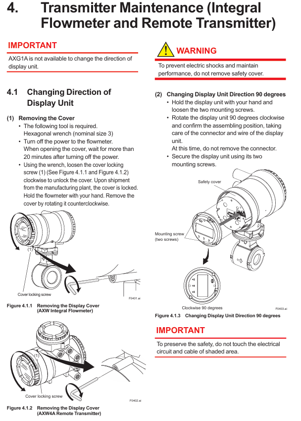
Depending on the type of device, there may be differences in the adjustment method, and power off is required first. The core steps are as follows:
Equipment type, caliber range, tool requirements, adjustment angle range, key considerations
Integrated flow meter+small caliber remote sensor 25-450mm (1-18 inches) No. 5 hex wrench -90 °,+90 °,+180 ° (one step every 90 °). It is forbidden to loosen the screws on the opposite side of the cable inlet; Tighten 4 bolts diagonally after adjustment
Large caliber remote sensor (Style S1) 500-1800mm (20-72 inches) with 1.5 hex wrench and 46 hex wrench -140 ° to+180 °. First loosen the hex nut, then loosen the neck screw, adjust and tighten in sequence
Large caliber remote sensor (Style S2) 500-1800mm (20-72 inches) 5 # hex wrench -90 °,+90 °,+180 ° (one step every 90 °) integrated flowmeter, do not loosen the screws on the opposite side
Note: The cable entry direction cannot be adjusted for submersible and district heating/anti condensation types (optional code DHC).
2. Maintenance of transmitter
(1) Display unit adjustment (only supported by AXW4A, not supported by AXG1A)
Direction adjustment: After power off, use a No. 3 hex wrench to open the cover, loosen the 2 fixing screws of the display unit, rotate clockwise 90 ° (do not remove the connector), re tighten the screws, close the cover and lock it.
Display board replacement: After opening the cover, loosen the screws of the display board, unlock the connector according to the "UNLOCK" mark and pull it out. When installing the new board, align the interfaces to avoid cable entanglement, and torque the screws to 0.6 ± 0.05 N · m.
(2) Parameter backup and recovery
Backup location: Parameters can be backed up to the built-in memory of the display board, supporting "backup restore" (same device) and "copy" (same model/specification/software and hardware version device).
Matching requirements: When restoring/copying, it is necessary to ensure that the device model, communication code, motherboard/sensor board/display board software version, etc. are consistent (see Table 4.4 in the manual). For split type, sensor device information should be synchronized with transmitter parameters.
3. Hardware switch settings
According to the device type (integrated, AXW4A, AXG1A), the switch functions are different, and the core settings are as follows:
(1) Integrated and AXW4A remote transmitter
The switch is located below the display panel, including address switch, burn switch, write protection switch, etc. Key settings:
Key points for setting switch type functions
When the CPU of the burn switch (SW1-1) fails, the default current output direction is high output (>21.6mA); Option C1/C2 low output (<2.4mA)
Write protection switch (SW1-2) to prevent parameter overwrite ON: prohibit modification; OFF: Allow modification (effective in combination with software write protection)
Address switch (Address) device address (Modbus/PROFIBUS PA/EtherNet/IP) Modbus: 1-127 (0 automatically converted to 1); EtherNet/IP: Set IP segment 4 (1-244, all OFF/ON automatically converted to 210)
The line terminal switch (SW2) for Modbus bus terminal matching should be set to "Bus end" at both ends of the bus (SW2-1/2 both ON, 150 Ω resistor); Set the intermediate device to 'Not bus end'
(2) AXG1A remote transmitter
Only includes burn out switch (SW1-1) and write protect switch (SW1-2), with the same logic as AXW4A. It needs to be operated after opening the cover (using the corresponding tool) to avoid touching unrelated circuits.
Sensor inspection and health diagnosis
1. Excitation coil and insulation resistance inspection (only for remote sensors)
(1) Coil inspection
Step: After power off, disconnect the sensor terminal cable and use a multimeter to measure the continuity of the "EX1" and "EX2" terminals. If there is no continuity, the coil will be disconnected; Resistance ≥ 150 Ω is considered abnormal and requires contact with Yokogawa for maintenance.
(2) Insulation resistance inspection
The split coil circuit and signal circuit require a 500V DC insulation tester, with the following standards:
Precautions for Circuit Type Test Terminal Requirements
Coil circuit EX1 (excitation terminal) - C (common terminal) ≥ 1 M Ω. Fluid inside the pipeline can also be tested
Signal circuits C-A and C-B (signal terminals) ≥ 100 M Ω require emptying the pipeline and drying. Explosion proof type testing is prohibited
Note: The submersible and DHC types need to be measured at the cable terminal, not the sensor terminal.
2. Verification function (device health diagnosis)
(1) Functional positioning
Diagnosis of magnetic circuit, excitation circuit, calculation circuit, equipment status, and wiring connections can be done without dismantling the equipment, taking about 15 minutes to complete. It is recommended to perform it once every 1-2 years and operate it under full capacity (air traffic control may cause diagnostic abnormalities).
(2) Operation process
Parameter setting: Enter "Device setup ► Diag/Service ► Verification" through the display unit or communication tool, and set "Mode" (No flow/Flow) and "Execute" (execute/not execute).
Result judgment: After diagnosis, check the "Result", "Passed" is normal, and "Failed" needs to be checked according to the manual flowchart (if the magnetic circuit is abnormal, check the grounding, and if the wiring is abnormal, rewire); Cancelled "may be caused by alarms (such as air traffic control, signal overflow) or flow noise, and the alarm needs to be resolved first.
Troubleshooting
The manual provides troubleshooting flowcharts for three types of core faults, with the following key steps:
1. No display
First, confirm if there are any error prompts (through display or communication tools). If there are no errors, check if the sensor arrow is consistent with the flow direction (can be reinstalled or set with reverse flow parameters), if the sensor is full, and if the electrode adhesion detection function is enabled (wait for 4 minutes after enabling).
If the electrode resistance is greater than 4M Ω, the sensor needs to be removed to clean the electrode/grounding ring of foreign objects; If the verification function is still abnormal, the insulation resistance needs to be checked. If it is invalid, contact Yokogawa.
2. Zero point instability
Priority should be given to confirming that the pipeline is full, free of bubbles, and has no leaks; Check the grounding (the grounding ring is not corroded, the grounding wire is not broken), and perform the no current state verification function.
The conductivity of the fluid must meet the specifications (if unstable, control the temperature/flow rate); Equipment close to motors, transformers, etc. needs to be shielded or kept away from interference sources.
3. The displayed traffic does not match the actual amount
Check whether the parameters (instrument coefficient, caliber, etc.) are correct, whether the pipe is full, and whether the zero adjustment is performed in a no flow state; The signal cable needs to be insulated (to avoid contact between the shielding layer and the conductor).
The upstream straight pipe section must meet the installation requirements (refer to the installation manual); Insufficient conductivity or fluid fouling require cleaning of electrodes/liners. If ineffective, check insulation resistance or use a calibrator to determine transmitter/sensor failure.
- OMRON
- ABB
- General Electric
- EMERSON
- Honeywell
- HIMA
- ALSTOM
- Rolls-Royce
- MOTOROLA
- Rockwell
- Siemens
- Woodward
- YOKOGAWA
- FOXBORO
- KOLLMORGEN
- MOOG
- KB
- YAMAHA
- BENDER
- TEKTRONIX
- Westinghouse
- AMAT
- AB
- XYCOM
- Yaskawa
- B&R
- Schneider
- KONGSBERG
- NI
- WATLOW
- ProSoft
- SEW
- ADVANCED
- Reliance
- TRICONEX
- METSO
- MAN
- Advantest
- STUDER
- DANAHER MOTION
- Bently
- Galil
- EATON
- MOLEX
- DEIF
- B&W
- ZYGO
- Aerotech
- DANFOSS
- Beijer
- Moxa
- Rexroth
- Johnson
- WAGO
- TOSHIBA
- BMCM
- SMC
- HITACHI
- HIRSCHMANN
- Application field
- XP POWER
- CTI
- TRICON
- STOBER
- Thinklogical
- Horner Automation
- Meggitt
- Fanuc
- Baldor
- SHINKAWA
- Other Brands
- UniOP
- KUKA
- Iba
- Beckhoff
-
 Basler BE1-57/27R Solid State Protective Relay
 -
 Basler BE3-25AX Time Overcurrent Relay
 -
 BASLER ELECTRIC BE1-24/A1EF1JC1N0F / BE124A1EF1JC1N0F Overvoltage Relay
 -
Basler Electric Solid State Protective Relay BE1-32R Style B2ED1PB0N0F
-
 Basler BE3-51-3E1E1 9320000110 24VDC Overcurrent Relay
 -
 Basler UFOV 260A Underfrequency Overvoltage Module
 -
 Basler 50F4EA1PA0N0F Instantaneous Overcurrent Relay
 -
 Basler BE1-50 Instantaneous Overcurrent Relay
 -
 Basler BE1-32 Solid State Protective Relay
 -
 Basler SCP 250-G-60 VAR Power Factor Controller
 -
Basler BE1-59N A5EE1KC0N0F Ground Fault Relay
-
Basler BE1-79A Reclosing Relay
-
Basler BE1-32R E1EA1OA0N0F Reverse Power Relay
-
 Basler DCQA-103 DCQC104-1 CMX-7D Circuit Board
 -
 Basler SSR125-12 Static Regulator 918500102
 -
 Basler 90 17709 112 Regulator Control Board
 -
 Basler AVC63-4 AVC634 Voltage Regulator
 -
 Basler 9 1049 04 100 PC Board Control Module
 -
 Basler SR4A-2B03B3A Static Voltage Regulator
 -
 Basler SR8A-2B15B3A Static Voltage Regulator
 -
 Basler KR7FFX Static Regulator 840V
 -
 Basler EL200-7 Voltage Regulator 90-660VAC 7A
 -
 Basler PRP210-1 Reverse Power Relay 9056300102
 -
 Basler SSR 63-12 Static Regulator 600VAC
 -
 Basler 9289901106 Digital Board
 -
Basler DECS100 Voltage Regulator DECS100A01
-
 Basler Electric CEM-2020 Contact Expansion Module
 -
Basler Electric BE3-25-1 C1 N4 Synchronizing Check Relay
-
 Basler Electric ACA2000-50GM GigE Camera 2MP 50fps
 -
 Basler Electric ACA2240-20GMSYM GigE Camera Sony IMX264
 -
 Basler BE1-50G Ground Overcurrent Relay
 -
 Basler PRS250 Veri-Sync Relay
 -
Basler MOC2199 Output Module
-
 Basler UFOV 260A Underfrequency Overvoltage Module
 -
 Basler BE-15482-001 Control Module
 -
Basler LSP4-7 Protective Relay
-
 Basler SCP 250-G-60 VAR Power Factor Controller
 -
Basler BE146N Negative Sequence Overcurrent Relay
-
Basler APR63-5 Automatic Voltage Regulator
-
Basler 9507900107 SR8A Retrofit Voltage Regulator
-
Basler BE1-320 Directional Power Relay
-
 Basler KR7F Voltage Regulator 9116200100
 -
Basler UFOV 260A Overvoltage Protective Module
-
 Basler AEC63-7 Analog Excitation Controller
 -
Basler 9992D90G01 Control Module
-
 Basler 6966D22G01 Control Board
 -
Basler 6965D40G01 Control Board
-
 Basler BE1-50/51M-104 Overcurrent Relay
 -
 Basler BE1-BPR Programmable Breaker Relay
 -
 BASLER Electric SSR 125-9 1256 00 102 Static Voltage Regulator
 -
 Basler Electric MVC 112 Manual Voltage Control
 -
 Basler Electric 9321000102 Control Module
 -
 Basler Electric RA-70-MDCT7 Rectifier Assembly
 -
 Basler Electric ACA1300-60GM GigE Camera
 -
 Basler Electric 6427C85G01 Interface Board
 -
Basler Electric 6965D05G01 Control Board
-
Basler Electric ACA2500-14UC Current Transducer
-
 Basler Electric 9170206111 Protective Relay
 -
 Basler Electric BE1-11-G6D1M1J1P0E000 Protection Relay
 -
Basler Electric BE1-50/51B-107 Overcurrent Relay
-
 Basler 9121000106 Voltage Controller
 -
 Basler B3E-E1P-A0N0F Solid State Protective Relay
 -
 Basler 9121000106 Manual Voltage Control
 -
Basler PRP320 Motor Pull-out Relay
-
 Basler SSE-N 250-9KW Shunt Exciter Regulator
 -
 Basler BE1-50-51B-107 Overcurrent Relay
 -
 BASLER ELECTRIC MVC 108 MANUAL VOLTAGE CONTROL MODULE 9 0370 00 102
 -
Basler BE1-59N-A7E-D1J-D0N0F Ground Overvoltage Relay
-
Basler BE1-46N-G1E-B8P-B0N0F Negative Sequence Overcurrent Relay
-
Basler BE1-951 Overcurrent Protection System
-
 Basler Electric MOC2199 Motor Operated Potentiometer
 -
 Basler Electric BE1-60 Voltage Balance Solid State Relay B1FA1C1M1F
 -
Basler Electric BE1-67N Directional Overcurrent Relay
-
Basler Electric PIA2400-17GM Interface Module
-
 Basler Electric V6RAB Rectifier Module
 -
Basler Electric BE1-32R Reverse Power Relay B2E E1R A0N1F
-
Basler Electric IFM-150 Firing Circuit Chassis 120V AC
-
 Basler Electric IFM-102 Firing Circuit Chassis 120V AC
 -
 Basler Electric 9170206111 NSNP Control Module
 -
Basler Electric SSR 63-12 Static Voltage Regulator
-
 Basler UFOV 260A Overvoltage Protective Module
 -
Basler SCA1300-32GM CCD Camera Lens Enclosure
-
 Basler BA1-27 Under Voltage Relay
 -
Basler 149D866G06 Control Board
-
 Basler 9072300130 Power Supply Module
 -
Basler CBS 305 Current Boost System
-
 Basler BE1-60 Voltage Balance Relay
 -
 Basler Electric CBS 212 Current Boost System Sensing 120/240VAC 50/60Hz 10VA
 -
 Basler MVC-300 Manual Voltage Control Unit
 -
Basler SSR125-12 Static Voltage Regulator 918500102
-
Basler SR32A2B05B3E Static Voltage Regulator
-
Basler Electric BE1-59N Ground Fault Overvoltage Relay
-
 Basler Electric 9110000113 Excitation Module
 -
Basler Electric 90-72300-114 Control Accessory
-
Basler Electric PRS-250 Protection Relay System
-
Basler Electric BE1-50/51M-109 Overcurrent Relay
-
 Basler Electric SR4A1B10B3E Static Voltage Regulator
 -
 Basler Electric CBS 212 Current Boost System
 -
Basler Electric SR32A2B05B3E Static Voltage Regulator
-
Basler Electric MOC2207 Motor Operated Potentiometer
-
 Basler Electric SR4A1B05A3E Static Voltage Regulator
 -
Basler Electric BE1-32R Power Relay B2EE1PA0N1F
-
Basler BEI-81 Underfrequency Relay
-
Basler CBS 212A Current Boost System
-
Basler SSR 63-12 Static Voltage Regulator
-
 Basler DGC-2020 Digital Genset Controller
 -
Basler BE1-32 Reverse Power Relay
-
 Basler BE1-50/51B-207 Overcurrent Relay
 -
Basler BE1-951 Overcurrent Protection System
-
 Basler 9073800-103 Power Supply
 -
Basler SCA1300-32FC CCD Camera
-
Basler 9073800-103 Power Supply
-
Basler SCA1300-32FC CCD Camera
-
 Basler L304KC Protective Relay
 -
 Basler BE3-25-1S1N4 Time Overcurrent Relay
 -
Basler 9032300113 Excitation Support System
-
Basler BE1-59N Ground Overvoltage Relay
-
Basler MVC-300 Manual Voltage Control Unit
-
Basler MOC2102 Potentiometer
-
 Basler BE1-87G Generator Differential Relay
 -
 Basler Electric DECS-200 Digital Excitation Control System
 -
Basler Electric DECS 125-15-B2C5 Digital Excitation System
-
 Basler Electric PLA2400-12GM Power Supply
 -
Basler Electric BE1-50/51B-235 Overcurrent Relay
-
Basler Electric BE1-27/59 Undervoltage Overvoltage Relay
-
Basler Electric CEM-2020 Contact Expansion Module
-
Basler Electric BE1-32R Solid State Power Relay
-
 Basler Electric BE1-700 Digital Generator Management Relay


