
Tektronix AFG1022 Function Generator
Tektronix AFG1022 Function Generator
Basic Information
Tektronix has released an official programming guide for the AFG1022 dual channel function generator, with the core goal of guiding users to achieve instrument automation control through SCPI (Standard Commands for Programmable Instruments), suitable for engineers who need to integrate AFG1022 into testing systems such as production line testing and laboratory automation.
Product core parameters: 2 independent channels, with a maximum bandwidth of 120MHz per channel, supporting 11 waveforms including sine wave, square wave, pulse wave, etc;
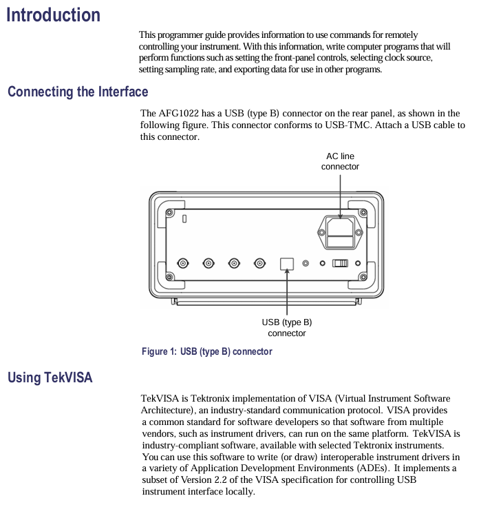
Supporting interfaces: GPIB (compliant with IEEE 488.2 standard), USB-TMC (USB 2.0 High Speed, compatible with USBTMC protocol);
Software compatibility: Supports mainstream VISA libraries such as TekVISA and NI-VISA, and can be called through programming languages such as Python, C #, LabVIEW, etc;
Document structure: Organized according to the sequence of "Command Fundamentals ->Function Control ->Interface Configuration ->Error Handling ->Appendix", containing a large number of command examples and code snippets.
SCPI Command Fundamentals (Programming Control Premiere)
1. Command structure and syntax rules
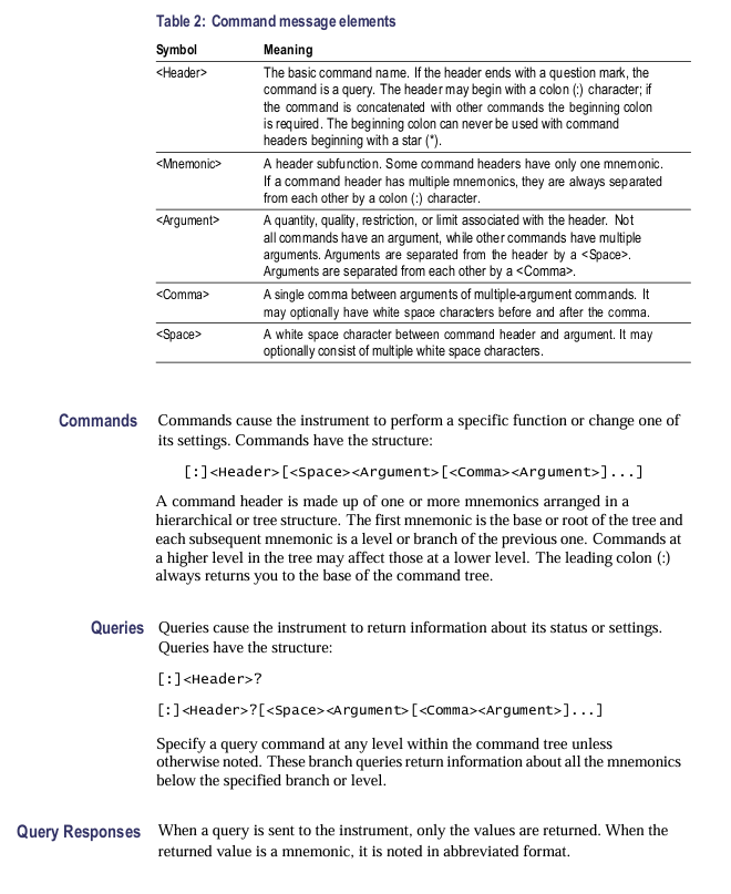
The SCPI command of AFG1022 adopts a hierarchical structure, separated by colons (:) to facilitate functional classification and memory. The core rules are as follows:
Example of Specific Explanation of Rule Categories
Hierarchical structure root command (e.g. SOURce)+sub command (e.g. FREQuency), channels can be omitted (default channel 1) Control channel 1 frequency: SOURce: FREQ 1000 (or SOURce: FREQ 1000); Control channel 2: SOURce2: FREQ 2000
Case sensitivity commands are not case sensitive, and parameter enumeration (such as ON/OFF) is also not sensitive: SOURce: WAVEform SIN is equivalent to: source: Waveform sin
The space rule allows for the addition of spaces between commands and parameters, as well as between parameters, without affecting parsing. SOURce: FREQ 1000 is equivalent to SOURce: FREQ 1000
The abbreviation rule command can use the first 3 characters for abbreviation (some commands support longer abbreviations): SOURce can be abbreviated as: SOU,: FREQuency can be abbreviated as: FRE
2. Command types and data formats
Command type:
Set command: used to configure instrument parameters, in the format of "command+parameter", with no return value;
Example: SOURce: VOLTage: AMPity 5 (set channel 1 amplitude to 5Vpp).
Query command: used to read the current parameters of the instrument, in the format of "command+question mark (?)", and return the corresponding value;
Example: SOURce: VOLTage: AMPlity? (Query the current amplitude of channel 1 and return "5.000000e+00").
Data format:
Example of Data Type Format Requirements
Numerical type supports integer (1000), decimal (1.234), Scientific notation (1e6) frequency setting: SOURCE: FREQ 1.234e6 (1.234MHz)
String type needs to be enclosed in double quotation marks ("), supporting letters, numbers, and special characters. Save settings: SYSTem: SETup: SAVE" MY_STUP1“
Enumeration type predefined options that require strict matching (case insensitive) waveform selection: SOURce: WAVEform SQUare, SOURce: WAVEform TRIangle
Core functional programming control (divided by functional modules)
1. Basic waveform generation and parameter control
AFG1022 supports 11 standard waveforms, and can select waveform types and configure core parameters (frequency, amplitude, DC offset, etc.) through SCPI commands. The parameter range and corresponding commands are as follows:
Function module core parameter range control command (channel 1 as an example) query command
11 types of waveform selection, including sine wave (SINusoid), square wave (SQUare), pulse wave (PULSe), etc.: SOURCE: WAVEform SINusoid: SOURCE: WAVEform?
Frequency setting output frequency: 0.1Hz~120MHz (sine wave/square wave); 0.1Hz~10MHz (pulse wave): SOURce: FREQuency 1000 (1kHz): SOURce: FREQuency?
Amplitude setting peak to peak amplitude of 10mVpp~20Vpp (50 Ω load); 20mVpp~40Vpp (high impedance load): SOURce: VOLTage: AMPlity 5 (5Vpp): SOURce: VOLTage: AMPlity?
DC offset DC offset voltage ± 10V (50 Ω load); ± 20V (high impedance load): SOURce: VOLTage: OFFset 2 (+2V): SOURce: VOLTage: OFFset?
Square wave duty cycle, such as wave height to level ratio of 10% to 90% (frequency ≤ 10MHz): SOURce: PULSe: DCYCle 50 (50%): SOURce: PULSe: DCYCle?
2. Advanced Function Control
(1) Modulation function (AM/FM/PM)
Support amplitude modulation (AM), frequency modulation (FM), phase modulation (PM), configurable modulation source (internal/external), modulation depth and other parameters:
Enable modulation: SOURce: MOD: STATe ON;
Select modulation type: SOURce: MOD: TYPE AM (AM modulation);
Configure internal modulation source frequency: SOURce: MOD: INTernal: FREQ 100 (100Hz modulation signal);
Configure AM modulation depth: SOURce: MOD: AM: DEPTh 50 (50% modulation depth).
(2) Trigger and synchronization
Supports internal triggering (continuous output), external triggering (controlled by external signals), and software triggering, suitable for synchronous multi device testing:
Select trigger source: TRIGger: SURce EXTernal (external trigger, trigger signal connected to TRIG IN interface of Rear panel);
Set trigger edge: TRIGger: EDGE RISING (rising edge trigger);
Execute software trigger: TRIGger: IMMediate (immediately trigger output once);
Trigger delay: TRIGger: DELay 0.1 (output delayed by 0.1 seconds after triggering).
(3) Setting up storage and calling
The current instrument configuration (waveform, parameters, modulation, etc.) can be saved to the internal storage area (supporting 10 user settings), and can be directly called later:
Save settings: SYSTem: SETup: SAVE "SET1", 1 (Save current settings as "SET1", Store location 1);
Call settings: SYSTem: SETup: LOAD 1 (setting to call storage location 1);
Delete setting: SYSTem: SETup: DELETE 1 (delete storage location 1 setting).
3. Multi channel control (AFG1022 has 2 channels)
Two channels are independently controllable, and channel 2 can be distinguished by adding 2 in the command. The example is as follows:
Channel 2 waveform selection: SOURce2: WAVEform TRIangle (Channel 2 outputs triangular waves);
Channel 2 frequency setting: SOURce2: FREQ 2000 (channel 2 frequency 2kHz);
Channel synchronization: SOURce: SYNC: STATe ON (synchronizes channel 2 with channel 1 in phase).
Interface configuration and communication implementation
1. Supported communication interfaces
AFG1022 provides two programming interfaces to meet different testing system requirements:
Advantages of Interface Type Standard Protocol Hardware Requirements
GPIB IEEE 488.2 requires GPIB cards (such as NI GPIB-US-HS) with strong anti-interference capabilities, suitable for industrial environments
USB-TMC USB 2.0 High Speed+USBTMC standard USB cable (A-B type) plug and play, no additional hardware required
2. Communication parameter configuration
GPIB interface: default address is 22, baud rate is 115200, data bit is 8, stop bit is 1, checksum is None; The address can be modified by the command: SYSTem: GPIB: DDRess 23 (set to 23).
USB-TMC interface: No manual parameter configuration is required, the system automatically recognizes it as a "USBTMC device" and can be directly connected through the VISA library (the resource name is usually USB0:: 0x0699:: 0x0368: C012345:: 0:: INSTR).
3. Typical Communication Example (Python+pyvisa)
Taking "Generate 1kHz sine wave and query amplitude" as an example, the steps are as follows:
Install dependency library: pip install pyvisa pyvisa py;
Write code:
python
Import pyvisa # Import VISA library
# 1. Initialize Resource Manager
rm = pyvisa.ResourceManager()
# 2. Connect AFG1022 (resource name can be queried through rm.list_desources())
afg = rm.open_resource("USB0::0x0699::0x0368::C012345::0::INSTR")
# 3. Send command: Channel 1 outputs a 1kHz sine wave with an amplitude of 5Vpp
Afg.write ("SOURce: WAVEform SINusoid") # Select sine wave
Afg.write ("SOURce: FREQuency 1000") # Frequency 1kHz
Afg.write ("SOURce: VOLTage: AMPlity 5") # amplitude 5Vpp
Afg. write (": OUTPut: STATe ON") # Enable output
# 4. Query the current amplitude
amplitude = afg.query(":SOURce:VOLTage:AMPlitude?")
Print (f "Current amplitude: {amplitude} Vpp")
# 5. Close connection
afg.close()
rm.close()
Generating
Error handling and debugging
1. Error code query and parsing
When the instrument executes a command error (such as parameter out of range, syntax error), an error code will be recorded, which can be queried and located through the command:
Query error: SYSTem: ERRor? (Return format: -221, "Parameter out of range");
Common error code parsing:
Error code, error description, possible causes, and solutions
-221 Parameter out of range Check if the parameter is within the specified range (e.g. frequency ≤ 120MHz)
-102 Syntax error command syntax error check command spelling (e.g. SOURce: FREQ mistakenly written as SOURce: FRE)
-256 Calibration required: The instrument has not been calibrated and the accuracy of the parameters cannot be guaranteed. Execute the calibration command (SYSTem: CALibrate) or contact after-sales service
0 No error command executed successfully-
2. Status Register and Status Query
By reading the status register, the current working status of the instrument can be obtained (such as whether it is outputting or triggering):
Operation status query: Status: Operation: CONDition? (Return 1 indicates normal operation, 0 indicates standby);
Event status query:: Status: EVENT: CONDition? (Return the event status code, such as 8 indicating trigger completion).
3. Debugging tools
Command echo: When enabled: SYSTem: ECHO ON, the instrument will return the received command for confirmation of whether the command was sent correctly;
Grammar check: Before sending a command, you can check the syntax using the command SYSTem: HECK: CMD (e.g. SYSTem: HECK: CMD ": SOURce: FREQ 1000");
Timeout setting: Set a timeout in the VISA library (recommended ≥ 1000ms) to avoid communication interruption caused by long command execution time (such as afg. timeout=2000).
Appendix Resources
Command index: a complete list of commands classified by "Source", "Trigger", and "System", including parameter descriptions and examples;
Example program: In addition to Python, it also provides control examples for C # and LabVIEW, covering scenarios such as waveform generation, modulation, and triggering;
VISA library compatibility: It explicitly supports TekVISA 4.0+and NI-VISA 5.0+, and it is not recommended to use older versions;
Firmware version description: Command differences between different firmware versions (such as some advanced commands requiring firmware ≥ 1.5.0).
Key issue
Question 1: How to ensure that the waveforms of two channels are "phase synchronized" when AFG1022 controls the output of two channels through SCPI commands? If there is still a phase deviation after synchronization, what commands can be used to adjust it?
answer:
1. Steps to ensure phase synchronization:
Enable channel synchronization function: Send command: SOURce: SYNC: STATe ON. At this time, the trigger signal of channel 2 will follow channel 1 to ensure that the output starting phase is consistent;
Unified trigger source: Set both channels' trigger sources to internal (TRIGger: SURCE INTernal) or the same external trigger (TRIGger: SURCE EXTernal) to avoid differences in trigger timing;
Same sampling clock: The two channels of AFG1022 share the same sampling clock without additional configuration, only ensuring that the channel synchronization function is enabled.
2. Phase deviation adjustment method:
If there is still a phase deviation after synchronization (such as channel 2 lagging behind channel 1 by 10 °), the phase of channel 2 can be fine tuned using the phase offset command:
Command format: SOURce2: PHAse: AJust<degrees>(phase adjustment range: -180 °~+180 °);
Example: SOURce2: PHAse: AJust 10 (leading channel 2 phase by 10 ° to offset the original lag);
Verification: Simultaneously collect the outputs of two channels through an oscilloscope, or check the phase setting (SOURce2: PHAse: ADJust?) to confirm the adjustment results.
Question 2: When using Python+pyvisa to control AFG1022 to generate a "10MHz square wave (duty cycle 30%, amplitude 8Vpp, DC offset 1V)", if the instrument does not output after executing the command, what are the possible reasons? Please list and provide troubleshooting steps according to priority.
answer:
1. Possible reasons and troubleshooting steps sorted by priority:
Steps for troubleshooting possible reasons for priority
1. Output not enabled. 1. Send query command: OUTPut: State? Confirm whether the return value is "ON";
If it is "OFF", send: OUTPut: STATe ON to enable output.
2 parameters exceed hardware limitations. 1. Check square wave frequency: 10MHz within the AFG1022 square wave frequency range (0.1Hz~120MHz), no problem;
2. Check the duty cycle: 30% is within the duty cycle range (10%~90%) corresponding to the 10MHz frequency, and there are no issues;
3. Check the amplitude and DC offset:
-Amplitude 8Vpp (maximum 20Vpp under 50 Ω load, compliant);
-DC offset 1V (± 10V under 50 Ω load, compliant);
-Key verification: amplitude+2 × DC offset ≤ 20V (8Vpp+2 × 1V=10V ≤ 20V, no overload).
3 command syntax errors 1. Check if the square wave configuration command is complete:
Correct command sequence:
-Choose square wave: SOURce: WAVEform SQUare;
-Set frequency: SOURce: FREQuency 10e6;
-Set duty cycle: SOURce: PULSe: DCYCle 30;
-Set amplitude: SOURce: VOLTage: AMPity 8;
-Set DC offset: SOURce: VOLTage: OFFset 1;
2. Enable command echo (SYSTem: ECHO ON), confirm that the sent command is consistent with the above and has no spelling errors (e.g. SOURce: PULSe: DCYCle mistakenly written as SOURce: SQARE: DCYCle).
4. Communication connection abnormality 1. Check VISA resource name: Confirm the resource name of AFG1022 through rm.list_desources() (e.g. USB interface is USB0:: 0x0699:: 0x0368:: C012345:: 0:: INSTR), ensure that the resource name connected in the code is correct;
2. Check the USB cable: Replace the USB 2.0 cable to avoid communication interruption caused by poor cable contact;
3. Restart the instrument: Power off and restart AFG1022 to establish a VISA connection again.
5 Instrument hardware failure 1. Execute self-test command: SYSTem: SELFtest? If "PASSED" is returned, it indicates that the hardware is normal. Otherwise, contact after-sales service;
2. Manual operation verification: Manually configure the same parameters through the instrument front panel, observe whether there is output, and rule out hardware problems other than programming control.
Question 3: In the "Modulation Function" of AFG1022, the "Modulation Depth" parameter range for AM modulation (amplitude modulation) is 0%~100%. Please explain the physical meaning of "Modulation Depth 50%" and use the SCPI command to implement "Channel 1 outputs a 100kHz sine wave carrier and uses a 1kHz sine wave for AM modulation (depth 50%, modulation source is internal)". At the same time, write a command sequence to query whether the modulation parameters have been successfully configured.
answer:
1. The physical meaning of "modulation depth 50%":
AM modulation (amplitude modulation) is the process of controlling the amplitude of a carrier signal through a modulation signal, causing the amplitude of the carrier signal to vary with the modulation signal. Modulation depth of 50% represents:
The maximum variation of carrier amplitude is 50% of the nominal amplitude of the carrier;
If the nominal amplitude of the carrier is 8Vpp, the range of amplitude variation of the modulated carrier is from "8Vpp -4Vpp=4Vpp" (minimum value) to "8Vpp+4Vpp=12Vpp" (maximum value);
When the modulation signal is a sine wave, the amplitude of the carrier wave varies sinusoidally with the modulation signal, and the amplitude of the variation is determined by the modulation depth (the greater the depth, the more significant the amplitude change).
2. Implement SCPI command sequence for AM modulation (channel 1):
Step Function SCPI Command Description
1. Select carrier waveform (sine wave): SOURCE: WAVEform SINusoid. The carrier is a sine wave
2. Set carrier frequency (100kHz): SOURce: FREQuency 100e3 Carrier frequency 100 × 10 ³ Hz
3. Set carrier amplitude (example 8Vpp): SOURce: VOLTage: AMPity 8. Carrier nominal amplitude 8Vpp
4. Enable modulation function: SOURce: MOD: STATe ON Enable modulation mode
5. Choose modulation type (AM): SOURce: MOD: TYPE AM modulation type is amplitude modulation
6. Select modulation source (internal): SOURce: MOD: SOURce INTernal. The modulation signal is generated internally by the instrument
7. Set internal modulation signal frequency (1kHz): SOURce: MOD: INTernal: FREQ 1e3 Modulation signal frequency 1 × 10 ³ Hz
8. Set AM modulation depth (50%): SOURce: MOD: AM: DEPTh 50 Modulation depth 50%
9. Open channel 1 output: OUTPut: STATe ON starts outputting AM modulation signal
3. Command sequence for querying whether the modulation parameters have been successfully configured:
SCPI query command expected return result (example)
1. Check if modulation is enabled: SOURce: MOD: STATe? 1 (indicates activation)
2. Query modulation type: SOURce: MOD: TYPE? AM "(stands for amplitude modulation)
3. Query modulation source: SOURce: MOD: SOURce? INT "(indicating internal source)
4. Query internal modulation signal frequency: SOURce: MOD: INTernal: FREQ? 1.000000e+03(1kHz)
5. Query AM modulation depth: SOURce: MOD: AM: DEPTh? 50.000000e+00(50%)
6. Query carrier frequency: SOURce: FREQuency? 100.000000e+03(100kHz)
7. Query carrier amplitude: SOURce: VOLTage: AMPity? 8.000000e+00(8Vpp)
- OMRON
- ABB
- General Electric
- EMERSON
- Honeywell
- HIMA
- ALSTOM
- Rolls-Royce
- MOTOROLA
- Rockwell
- Siemens
- Woodward
- YOKOGAWA
- FOXBORO
- KOLLMORGEN
- MOOG
- KB
- YAMAHA
- BENDER
- TEKTRONIX
- Westinghouse
- AMAT
- AB
- XYCOM
- Yaskawa
- B&R
- Schneider
- KONGSBERG
- NI
- WATLOW
- ProSoft
- SEW
- ADVANCED
- Reliance
- TRICONEX
- METSO
- MAN
- Advantest
- STUDER
- DANAHER MOTION
- Bently
- Galil
- EATON
- MOLEX
- DEIF
- B&W
- ZYGO
- Aerotech
- DANFOSS
- Beijer
- Moxa
- Rexroth
- Johnson
- WAGO
- TOSHIBA
- BMCM
- SMC
- HITACHI
- HIRSCHMANN
- Application field
- XP POWER
- CTI
- TRICON
- STOBER
- Thinklogical
- Horner Automation
- Meggitt
- Fanuc
- Baldor
- SHINKAWA
- Other Brands
- UniOP
- KUKA
- Iba
- Beckhoff
- ADLINK
-
 Basler Electric DECS-250-CN1SN1N Digital Excitation Control System
 -
 Basler Electric BE1-700 E0N2X1N Digital Protective Relay
 -
 Basler Electric SR4A-2B15B3A Static Voltage Regulator 120VAC 50/60Hz
 -
 Basler Electric 9261402111 PCB Control Board 9346000033
 -
 Basler Electric BE28053-002 Transformer BE28053002
 -
 Basler Electric BE3-25A Auto Synchronizer B1D Sync Module
 -
 Basler Electric BE3-GPR Generator Protective Relay
 -
 Basler Electric SCP-250-G-60 VAR Power Factor Controller 9 1100 00 109
 -
 Basler Electric BE3-32-1S1N1 Reverse Power Relay 277V 5A
 -
 Basler Electric ACA1300-60GM Area Scan Camera 106200-17
 -
 Basler Electric UFOV 260 A Protection Module Specs
 -
 Basler Electric BE03303001 Control Module
 -
Basler Electric BE3-GPR-P1BVSF Generator Protective Relay
-
 Basler Electric BE1-87G Solid State Protective Relay Guide
 -
 BASLER ELECTRIC BE1-60 VOLTAGE BALANCE RELAY T176884
 -
 Basler Electric BE1-32R Protective Relay
 -
 Basler Electric 9022900-103 Transformer 6-7VA 60Hz
 -
 Basler Electric BE1-59-A4E-E1K-B1S3F Overvoltage Relay
 -
 Basler Electric KR2FF-M Voltage Regulator 9 1163 00 103
 -
 Basler Electric UFOV 260 A Protective Module
 -
 Basler Electric PCB Assembly 9059701100 919620
 -
 Basler Electric SR8A2B01A3E Static Voltage Regulator
 -
 Basler Electric SSR125-12 Static Voltage Regulator 9185900102
 -
 Basler Electric SSR 63-12 Static Voltage Regulator 600VAC
 -
 Basler Electric BE1-60 Solid State Protective Relay
 -
 Basler Electric BE3-47N/27-3A4N2 Voltage Relay 9320400101
 -
 Basler Electric BE1-59 Over Voltage Relay
 -
 Basler Electric DECS100-B15 Automatic Voltage Regulator
 -
 Basler Electric PRS250 Veri-Sync Relay 9088800102
 -
Basler Electric BE25927001 Current Transformer 1:34 Amp
-
Basler Electric 9170818100 Generator Differential Relay
-
 Basler Electric BE1-59N Solid State Ground Fault Overvoltage Relay
 -
 Basler Electric 1783 DC Current Transformer Coil 1200:5A
 -
Basler Electric BE1-67 Ground Directional Overcurrent Relay
-
 Basler Electric UFOV-260A Underfrequency Overvoltage Module
 -
 Basler Electric BE10493001 Control Module
 -
Basler Electric SSR125-12 Static Voltage Regulator Guide
-
 Basler Electric BE1810/U-2 Solid State Frequency Relay Guide
 -
 Basler Electric 9105100106 UFOV-250A Protector Guide
 -
 Basler Electric MOC2199 9072300-335 Relay Module Guide
 -
 Basler Electric 9289902106 Circuit Board
 -
Basler Electric BE1-32R Protective Relay A1E E1P BOS1P
-
 Basler Electric RAL6144-16GM GigE Line Scan Camera with Lens
 -
 Basler Electric BE3-49R-5I5A1 Temperature Relay
 -
 Basler Electric BE1-32R Power Relay B3E E1R A0N1F
 -
 Basler Electric SR4A2B06B3A Static Voltage Regulator Features
 -
 Basler Electric 9121000106 Manual Voltage Control MVC Guide
 -
Basler Electric SR32A-2B15B3E Static Voltage Regulator
-
 Basler Electric SR4A2B06B3A Static Voltage Regulator Guide
 -
Basler Electric 801A193F02 Hammond Transformer Module
-
 Basler Electric BE1-24 Volts Per Hertz Relay A1E F1J D1S0F
 -
 Basler Electric AEC63-7 Analog Excitation Controller 220-277V
 -
Basler Electric BE132R Power Relay T245579
-
 Basler Electric MVC 108 Manual Voltage Control 90 37000 102
 -
 Basler Electric 9022900-103 Control Transformer 6-7VA 60Hz
 -
 Basler Electric BE1-79M Plug Adapter 9170111102
 -
 Basler Electric 9 2007 00 100 Current Boost System CBS 305
 -
 Basler Electric SR4A2B01B3A Static Voltage Regulator 120V
 -
Basler Electric BE1-32R Power Solid State Relay E2E A10 A0N0F
-
Basler Electric PRS250 Veri-Sync Relay 9088800102
-
 Basler DECS 125-15-B2C Digital Excitation Control
 -
 Basler BE 13693 002 Transformer
 -
Basler BE1-59N Ground Fault Overvoltage Relay
-
 Basler BE1-79A Reclosing Relay
 -
Basler 9-1051-00-105 Overload Protection Module
-
 Basler BE1-32R Power Relay – Directional Overcurrent Guide
 -
 Basler 9319700103 BE3-27T/59T-3A1N3 Voltage Relay
 -
Basler BE1-87G Generator Differential Relay
-
 Basler BE3-25-1D1N4 9319100106 480V Relay
 -
 Basler SR8A2B07B3A Static Voltage Regulator
 -
 Basler Electric BE4-27/59 Over/Under Voltage Relay 307-2552
 -
Basler Electric SR32A2B05B3E Static Voltage Regulator
-
Basler Electric BE1-27 A3E C3J A1N6F Solid State Protective Relay
-
 Basler Electric 9174700-100 Excitation Limiter Generator
 -
Basler Electric BE1-87G Generator Differential Relay 09833
-
 Basler Electric 9310200100 Power Supply Module
 -
 Basler Electric TIEE1CD0N07 Control Module
 -
Basler Electric BE1-59N Ground Fault Relay T214750
-
Basler Electric SR8A2B10B3AX Static Voltage Regulator 9060200126
-
 Basler Electric SSR 125-12 Voltage Regulator
 -
 Rolls Royce H1111.0204 Ship Main Controller
 -
 Basler Electric BE3-32-3AC Reverse Power Relay 9 1376 00 105
 -
Basler Electric BE3-25-1A1N4 Synch Check Relay 9319100100
-
 Basler Electric SR4A-2B15B3A Static Voltage Regulator
 -
 Basler Electric SR4A-2B15B3E Static Voltage Regulator
 -
 Basler Electric 9170818100 Solid State Protective Relay
 -
 Basler Electric AEC63-7 Analog Excitation Controller
 -
Basler Electric 17483 Auxiliary Module
-
Basler Electric BE1-59 Over Voltage Relay
-
Basler Electric 21600-101 Control Module
-
 Basler Electric KR2F Generator Voltage Regulator 9056600100
 -
Basler BE1-CDS Current Differential System
-
 Basler Electric CBS 212 Current Boost System 9 2650 00 100
 -
 Basler Electric IFM-150 Firing Circuit Chassis
 -
 Basler Electric BE1-60 Voltage Balance Relay C1F A1P D0C3F
 -
Basler Electric BE1-32R Power Relay A2E D1R A0N0F
-
Basler Electric BE1-32R Power Relay A2E D1R A0N0F
-
 Basler Electric 8650C80G01 Isolation Transducer PCB Board
 -
 ETEL EA-P2M-300-4/7.5A-0100-01 AccurET Modular 300 Servo Drive
 -
Basler Electric 87T Transformer Differential Relay
-
Basler Electric BE-6868 Power Transformer 5950007559202
-
 Basler Electric PRS250 Veri-Sync Relay 9088800102
 -
 Basler Electric SCP-250-G-60 VAR Power Factor Controller
 -
 Basler DECS-150 AVR 1NS2V1N1S Voltage Regulator
 -
Basler UFOV 260A Under Frequency Overvoltage Module
-
 Basler MOC2 199 Motor Operated Control – Overview and Setup
 -
 Basler BE3-49R-5K5A1 Temperature Relay – Complete Guide
 -
Basler BE 20035 001 Transformer – Technical Data and Installation
-
Basler BE 02727 001 Transformer – Specifications and Usage
-
 Basler BE127 Under Voltage Relay – Features and Application Guide
 -
Basler CBS377 Current Boost System – Complete Technical Guide
-
Basler BE1-87G P/N 9170818100 Differential Relay – In-Depth Specs
-
Basler BE1-87G Generator Differential Relay – Technical Overview
-
Basler Electric SR4A2B16 SVR Static Voltage Regulator – Complete Guide
-
Basler Electric 9261500101 Power Supply Module
-
 Basler Electric AEM-2020 Analog Expansion Module
 -
Basler Electric DGC-2020 Digital Genset Controller 51BRBNEAH001
-
Basler Electric BE1-59N Ground Fault Overvoltage Relay
-
Basler Electric BE1-59N-A5E-E1L-N0S1F Neutral Overvoltage Relay
-
Basler Electric MOC2499 Motor Operator Control Potentiometer 9072300430
-
 Basler Electric BE1-50/51M Overcurrent Relay
 -
 Basler Electric 9148100106 MOC3502 Solid State Relay 250VDC 0.25A
 -
 Basler Electric CBS 212 Current Boost System 9265000100
 -
Basler Electric 10493002 Control Module
-
Basler BE1-32R D3E E1R A0N1F Power Relay
-
 Basler SR8A2B15B3A Static Voltage Regulator
 -
 Basler IFM-105 Firing Circuit Chassis 9324100105
 -
Basler SR4A2B05B3A Static Voltage Regulator


