
TEKTRONIX AFG31000 series arbitrary function generator
TEKTRONIX AFG31000 series arbitrary function generator
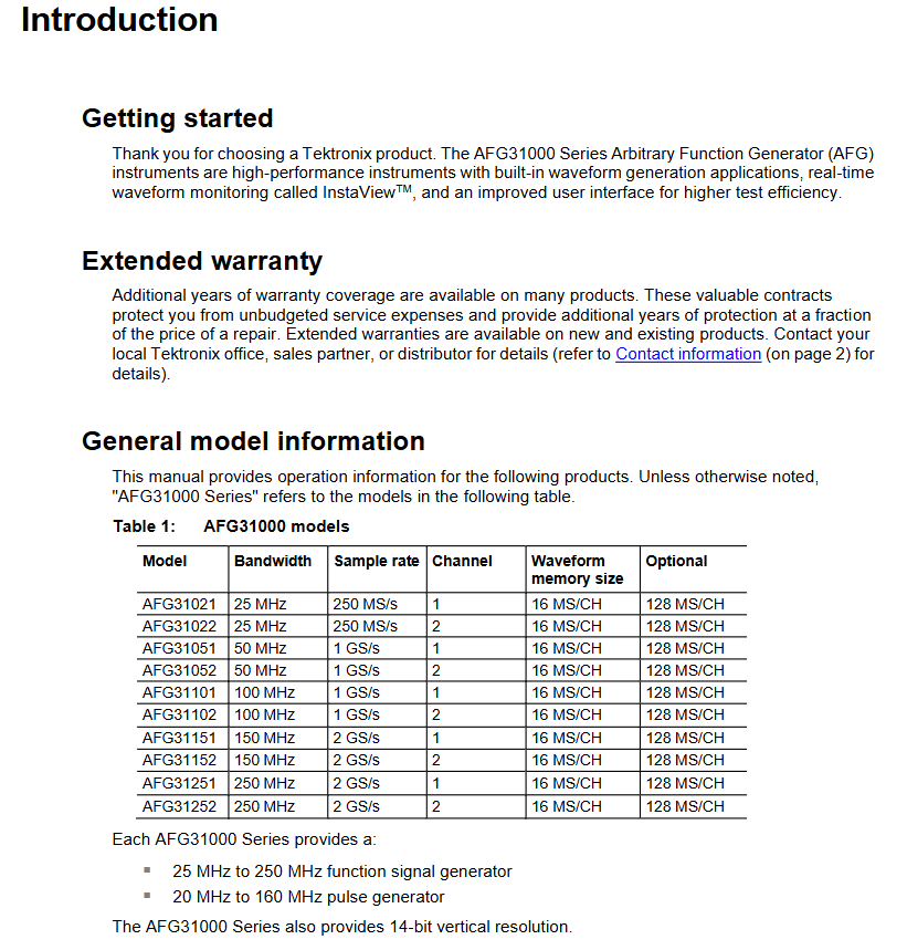
Product model and core parameters
1. Comparison Table of Model Parameters
Model, bandwidth, sampling rate, number of channels, standard memory, optional memory, pulse generator, bandwidth
AFG31021 25MHz 250MS/s 1 16MS/CH 128MS/CH 20MHz
AFG31022 25MHz 250MS/s 2 16MS/CH 128MS/CH 20MHz
AFG31051 50MHz 1GS/s 1 16MS/CH 128MS/CH 40MHz
AFG31052 50MHz 1GS/s 2 16MS/CH 128MS/CH 40MHz
AFG31101 100MHz 1GS/s 1 16MS/CH 128MS/CH 80MHz
AFG31102 100MHz 1GS/s 2 16MS/CH 128MS/CH 80MHz
AFG31151 150MHz 2GS/s 1 16MS/CH 128MS/CH 120MHz
AFG31152 150MHz 2GS/s 2 16MS/CH 128MS/CH 120MHz
AFG31251 250MHz 2GS/s 1 16MS/CH 128MS/CH 160MHz
AFG31252 250MHz 2GS/s 2 16MS/CH 128MS/CH 160MHz
2. General technical characteristics
Vertical resolution: 14 bits, ensuring waveform accuracy.
Output impedance: default 50 Ω, can be set to 1 Ω~10k Ω (resolution 1 Ω) or Infinity (>10k Ω).
Modulation types: Supports AM (amplitude modulation), FM (frequency modulation), PM (phase modulation), FSK (frequency shift keying), PWM (pulse width modulation).
Environmental adaptability: working temperature of 0 ℃~40 ℃, humidity of 5%~85% RH, working altitude of 3000m.
Safety regulations and operating taboos
1. Core security principles
Only for professional operation: Only personnel with high voltage/high frequency testing qualifications are allowed to operate, and non professionals are prohibited from contacting.
System level security: If connecting to a large system, it is necessary to comply with the security manuals of other components of the system.
Preoperative examination: Before use, verify that the device is functioning properly with a known signal source and prohibit its use for detecting dangerous voltages.
2. Key operations for preventing electric shock and fire prevention
(1) Power supply and grounding
Use designated power cords (must comply with local certification), and do not mix power cords from other devices.
The equipment is grounded through the power cord, and the grounding conductor must be connected to the ground. It is forbidden to disconnect the grounding connection.
Confirm that the power supply voltage matches the rated value of the equipment (such as 100V~240V AC) before powering on.
(2) Connection/disconnection sequence
Operation type, step purpose
Connect circuit 1. Connect the probe output to the measuring instrument → 2 Connect the probe reference terminal to the tested circuit → 3 Connect the probe input to avoid electric shock or equipment damage caused by live plugging and unplugging
Disconnect circuit 1. Disconnect probe input and reference terminal → 2 Disconnect the probe from the instrument to prevent residual voltage shock
(3) Taboos on Environment and Equipment Status
Do not use in damp, explosive, and dusty environments, and do not operate without cover plates/panels (exposing high-voltage circuits).
If the equipment falls, gets wet, or is suspected of damage, authorized personnel must inspect it before use, and it is prohibited to disassemble it by oneself.
Do not touch the exposed circuit when powered on, and keep the probe body and output line away from the tested circuit.
Remote control interface and instruction system
1. Interface configuration
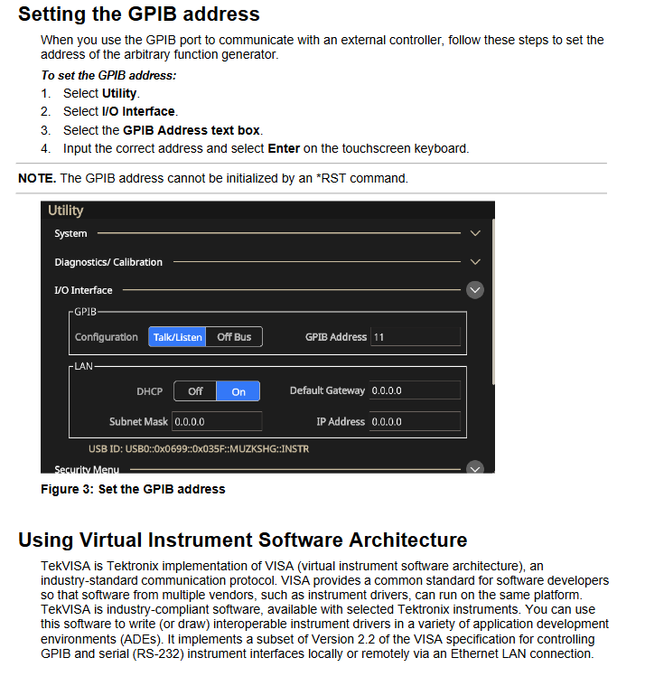
(1) GPIB interface
Requirements:
Each device must have a unique address (1-30) and must not be duplicated;
The bus can connect up to 15 devices, with a total cable length of ≤ 20m and at least 1 device per 2m;
Power on devices account for ≥ 67%, support star/linear topology, and prohibit parallel/ring topology.
Address setting: Enter the address through the panel "Utility → I/O Interface → GPIB Address" (* RST command cannot initialize the address).
(2) VISA interface
TekVISA software (official website download) needs to be installed, supporting GPIB, RS-232, Ethernet remote control, and complying with VISA 2.2 standard.
Applicable development environment: Windows system, supporting ADE (Application Development Environment) such as LabVIEW and VB.
2. Instruction system and syntax
(1) Instruction classification
Example Function of Instruction Type
IEEE 488.2 General Command * CAL? 、 *CLS, * RST self calibration, clear register, reset
SCPI command SOURce1: FUNCTION SIN, OUTPut1: STATe ON. Set the waveform of channel 1 to sine and enable the output of channel 1
(2) Core Grammar Rules
Abbreviation: Commands can be abbreviated (uppercase is required, lowercase can be omitted), such as DISPlay: BRIGhtness can be abbreviated as DISP: BRIG.
Chain command: Multiple commands are separated by semicolons, and prefixes can be omitted for the same root node, such as TRIGger: CLOPe POS; SOURce SIN (assuming the trigger slope is positive and the source waveform is sine).
SI units: support voltage (V/mV), frequency (Hz/kHz/MHz), time (s/ms/μ s/ns), etc., such as Frequency 10MHz (assuming frequency 10MHz).
Parameter type: Supports Boolean values (ON/OFF), numerical values (NR1/NR2/NR3), and strings (quotation marks required), such as MMEMory: DELete "U:/TEST. TFWX" (remove the TEST. TFWX file from USB).
Detailed explanation of core functions and instructions
1. Waveform generation and output control
(1) Waveform type and parameter settings
Supporting waveforms: 13 types including sine (SINusoid), square wave (SQUare), pulse (PULSe), ramp (RAMP), noise (PRNoise), arbitrary wave (EMEMory/EFILe), etc.
Example of Key Instructions:
Let the waveform of channel 1 be sine: SOURce1: FUNCTION SIN
Assuming a frequency of 10kHz: SURce1: Frequency 10kHz
Set amplitude to 2Vpp: SURce1: VOLTage: Amplitude 2VPP
Set offset 1V: SURce1: VOLTage: OFFSet 1V
(2) Output control
Turn on/off output: OUTPut1: STATe ON/OFF
Output polarity reversal: OUTPut1: Polarity Inverted (default NORMAL)
Output impedance setting: OUTPut1: Impedance 50OHM (default 50 Ω, can be set to 1 Ω~10k Ω)
2. Modulation function (AM/FM/PM, etc.)
Taking AM (amplitude modulation) as an example, the key instructions are as follows:
Example of functional instructions
Set modulation depth SOURce1: AM: DEPTh SOURce1: AM: DEPTh 50PCT (50% depth)
Set the internal modulation frequency SOURce1: AM: INTernal: FREQuency SOURce1: AM: INTernal: FREQuency 1kHz
Set modulation source SOURce1: AM: SOURce1: AM: SOURce INTernal (internal source)
Turn on AM SOURce1: AM: STATe SOURce1: AM: STATe ON
3. Sequence control (advanced mode)
Support defining 256 sequence elements to achieve waveform looping, jumping, and waiting for triggering. Core instructions:
New sequence: SEQueen: NEW
Set sequence length (10 elements): SEQuence: LENGth 10
Let element 1 loop 100 times: SEQuence: ELEM1: LOOP: COUNT 100
After triggering element 1, jump to element 6: SEQuence: ELEM1: GOTO: INDex 6; GOTO:STATe ON
Running sequence: SEQControl: RUN: IMMediate
4. Data storage and management
(1) Virtual Disk Definition
Disk identification, storage location, permission usage
U: USB flash storage for reading and writing user waveforms/settings files
M: Internal flash read-write storage commonly used waveforms/settings
P: Internal predefined area read-only storage factory preset waveforms (such as sine and square waves)
(2) Store/load instructions
Save channel 1 waveform to USB: MMEMory: STORe: TRACe EMEMory1, "U:/WAVE1. TFWX"
Loading settings from USB to memory 1: MMEMory: LOAD: STATe 1, "U:/SET1. TFS"
Delete USB file: MMEMory: DELete "U:/OLD. TFWX"
Status and Event Management
1. Status register system
Compliant with IEEE 488.2 and SCPI standards, the core registers are as follows:
Meaning of register name function key bits
Status Byte Register (SBR) summarizes device status OSB (operational status), ESB (event status), MAV (message available)
The Standard Event Status Register (SESR) records core events OPC (operation completed), CME (command error), EXE (execution error)
The operating condition register (OCR) records the operating status CAL (calibration in progress), SWE (scanning in progress), WTRIG (waiting for trigger)
2. Error code system
Error codes are divided into "standard errors" (-100~-499) and "device specific errors" (1~32767). Common examples include:
Error code type description
-100 command errors command syntax errors (such as spelling errors)
-222 execution error parameter out of range (e.g. frequency set to 1000MHz, exceeding the upper limit of 250MHz)
-350 device error error queue overflow (more than 64 events)
1101 calibration error CH1 internal offset calibration failed
2305 self-test error CH1 output gain self-test failed
3. Error query
Search for the next error: SYSTem: ERRor: NEXT? The return format is -222, "Data out of range"
Maintenance and troubleshooting
1. Maintain standards
Cleaning: Wipe the outer surface with a dry lint free cloth or 75% isopropanol. Do not use water/solvents/abrasives, and do not allow moisture to enter the interior of the equipment.
Repair restriction: There are no user repairable parts, and only DC offset can be adjusted for serial numbers C019999 and below. Other faults need to be returned to the factory.
2. Common fault handling
Troubleshooting steps for possible causes of fault phenomena
No waveform output turned on, parameter out of range 1. Execute OUTPut1: STATe? Confirm the output status; 2. Check if the frequency/amplitude is within the device range
GPIB no response address conflict, cable fault 1. Confirm that GPIB address is unique; 2. Replace GPIB cable; 3. Restart the device and controller
Calibration failed due to excessive temperature and humidity in the environment, hardware malfunction. 1. Confirm that the environment is 0 ℃~40 ℃/5%~85% RH. 2. Execute DIAGnostic? Self inspection; 3. If errors 1101-1216 are reported, return to the factory for repair
- OMRON
- ABB
- General Electric
- EMERSON
- Honeywell
- HIMA
- ALSTOM
- Rolls-Royce
- MOTOROLA
- Rockwell
- Siemens
- Woodward
- YOKOGAWA
- FOXBORO
- KOLLMORGEN
- MOOG
- KB
- YAMAHA
- BENDER
- TEKTRONIX
- Westinghouse
- AMAT
- AB
- XYCOM
- Yaskawa
- B&R
- Schneider
- KONGSBERG
- NI
- WATLOW
- ProSoft
- SEW
- ADVANCED
- Reliance
- TRICONEX
- METSO
- MAN
- Advantest
- STUDER
- DANAHER MOTION
- Bently
- Galil
- EATON
- MOLEX
- DEIF
- B&W
- ZYGO
- Aerotech
- DANFOSS
- Beijer
- Moxa
- Rexroth
- Johnson
- WAGO
- TOSHIBA
- BMCM
- SMC
- HITACHI
- HIRSCHMANN
- Application field
- XP POWER
- CTI
- TRICON
- STOBER
- Thinklogical
- Horner Automation
- Meggitt
- Fanuc
- Baldor
- SHINKAWA
- Other Brands
- UniOP
- KUKA
- Iba
- Beckhoff
- ADLINK
-
 GE Fanuc VMIVME-5588 High-speed Reflective Memory Board
 -
 VMIC VMIVME-5565 Reflective Memory Board
 -
 VMIC VMIVME-2127 Voltage Source Digital Output Board
 -
 VMIC VMIVME 4512 Analog VME Process PCB Assembly
 -
 GE Fanuc VMIVME-3122-022 Analog I/O Module
 -
 VMIC VMIVME 5576 High Speed Fiberoptic Network Board
 -
 FANUC VMIVME-7452 VMEbus Analog I/O Board
 -
 FANUC VMIVME-2210 VMEbus Digital Output Board
 -
 FANUC VMIVME-7750-734000 VMEbus Single Board Computer
 -
 VMIC VMIVME 2210 VMEbus DO 28V Digital Output Board
 -
 VMIC VMIVME DR11W VMEbus DMA Interface Module
 -
 VMIC VMIVME-2536-200 5V Optically Coupled Digital I/O Board
 -
 VMIC VME-7754 VMIVMF7754-259000 VMEbus Control Card
 -
 VMIC 2170A VME Interface Board
 -
 GE VMIC PMC-5565PIORC-210000 Reflective Memory PMC Node Card
 -
 VMIC VMIVME-7750-750000 VME Single Board Computer
 -
 VMIC VMIVME-7751 VME Single Board Computer
 -
 VMIC 332-004512 Analog VME Process Board
 -
 VMIC VMIVME2528 VME Interface Board
 -
FANUC VMIVME-2120 VME Bus Interface Board
-
 FANUC VMIVME-2540 VME Bus Interface Board
 -
 FANUC VMIVME-3230 VME Bus Interface Board
 -
 FANUC VMIVME-4514 VME Bus Interface Board
 -
 ETEL DSB2S154-211E-000H Servo Amplifier
 -
 ETEL DSCQT112-111-000 Motion Control Module
 -
 ETEL LMG20-050-3QB-211A Servo Motor – High Torque Linear
 -
 ETEL EU-LCP-0-0-1000-01 Communication Card
 -
 ETEL DSA2P174ZA-033A Servo Amplifier Driver
 -
 ETEL EA-P2M-400-15/40A-0100-00 Servo Driver
 -
 ETEL DSC2P152-111-000 Servo Drive Amplifier
 -
 ETEL LMS15-050-3UA-209A Linear Motor
 -
ETEL DSC2P152-111D-000A Controller
-
 ETEL DSB2P131-111E-000B Digital Servo Amplifier Position Controller
 -
 ETEL DSO-PWR111C-000B Power Supply Module
 -
 ETEL DSCDP324-321F-000C Servo Driver
 -
 ETEL DSC2P152-111B-000D Controller
 -
 ETEL DSB2P142-111E-000H Circuit Board
 -
 ETEL LMG05-030-3QA-H01 Linear Motor
 -
 ETEL DSC2P152-111F-000A Controller
 -
 ETEL DSA2S211ZA Servo Drive
 -
 ETEL DSCDM332-112-000 Drive Module
 -
 ETEL DSCDP334-421-000 Digital Position Controller Servo Drive
 -
ETEL EA-P2M-400-15/40A-0100-00 AccurET Servo Drive
-
 ETEL TMA0140-050-3UB-202B Torque Motor
 -
 ETEL DSA1DL1D.PCB Servo Drive Board
 -
 ETEL DSA2DL 1A Servo Drive
 -
 ETEL DSMAX111B-000B Servo Drive
 -
ETEL DSO-PWS111C-000B Power Supply Module
-
 ETEL DSC2P142-111B-000D Servo Drive Amplifier
 -
 ETEL DSC2P132-111D-000A Servo Drive Amplifier
 -
ETEL DSC2P152-111B-000D Servo Drive Amplifier
-
ETEL DSB2P131-121E-000H Servo Drive Amplifier
-
 ETEL DSB2P142-111E-000H Servo Drive Amplifier
 -
ETEL DSO-PWR112C-000A Power Supply Module – High Power
-
ETEL DSO-PWR111C-000A Power Supply Module
-
ETEL DSB2P121-121E-000H Servo Drive Amplifier
-
 ETEL DSB2S134-111E-000H Digital Servo Amplifier
 -
 ETEL RTMA0140-070-AQN-21E Motor
 -
ETEL DSCDP132-111-000 Dual Controller Circuit Board – Motion Control
-
 ETEL LMS15-050-3UA-209Aft Linear Motor
 -
 ETEL DSCDP324-322G-000A Position Controller
 -
ETEL DSA2P174ZA-033A Servo Amplifier Driver
-
 ETEL DSA2P174ZA-017A Servo Amplifier Driver
 -
 ETEL LMD10-050-3QA-223A Linear Motor
 -
ETEL EU-LGP-0-0-1000-00 PCI Network Card
-
ETEL DSO-PWS111C-000B Power Supply Module
-
ETEL DSC2V174-111C-001A Servo Controller
-
 ETEL EA-P2M-600-15/40A-0000-01 AccurET Modular Position Controller
 -
 ETEL RTMA0140-070-AQN-21B DD Motor
 -
 ETEL DSC2P144-421-000 Servo Driver
 -
ETEL EA-P2M-400-15-40A-0100-00 Servo Drive
-
ETEL DSCDM341-111C-000B Board
-
 ETEL LMD10-050-3QA-223A Motor
 -
ETEL RTMA0140-070-AQN-21E DD Motor
-
 ETEL DSCDM342-111-000 Servo Variator
 -
ETEL DSC2P152-111E-000A Servo Amplifier
-
ETEL LMS15-050-3UA-209A Motor
-
ETEL RTMA0140-070-AQN-21C DD Motor – High Torque Direct Drive
-
 ETEL DSCDP334-421G-000A Servo Drive
 -
Etel DSB2S154-211E-000H Digital Servo Amplifier
-
 ETEL EA-P2M-400-15/40A-0100-00 AccurET Servo Drive
 -
 ETEL DSA2P-174ZA-017A Digital Servo Amplifier
 -
ETEL EA-P2M-400-15/40A-0100-00 Servo Drive
-
ETEL LMP07-100-3TAS-229 Linear Motor Primary Part
-
ETEL LMA11-120-3ZA-359A Linear Motor
-
 ETEL EA-S0M-400-40/80A-0000-00 Drive Power Supply
 -
Etel DSCDP334-421-000 Driver
-
ETEL DSCDM341-111C-000B DSCDM Drive Board
-
Etel DSA1 Digital Servo Amplifier
-
ETEL DSA2P174ZA-033A Servo Amplifier
-
ETEL DSCDM342-111-000 Servo Verifier
-
 ETEL LMS15-050-3UA-209A Linear Motor
 -
ETEL P2M-048-2.5/5A AccurET Position Controller – Modular
-
ETEL LMD10-050-3QA-223A Linear Motor – Compact Precision
-
 ETEL EA-P2M-400-05/10A-0000-01 Drive – Precision Motion
 -
ETEL LMP07-100-3TAS-229 Linear Motor Primary Part
-
 ETEL EU-LGP-0-0-0000-00 Motion Control Card – Precision Control
 -
 ETEL DSC2P152-111E-000A Servo Amplifier
 -
ETEL EA-P2M-400-15/40A-0100-01 Servo Drive
-
 ETEL EA-SOM-300-40/80A-0000-00 AccurET Power Supply Module
 -
ETEL LMG10-1050-3QA-H01 Linear Motor
-
 ETEL EA-SOM-300-40/80A-0000-00 AccurET Modular Power Supply
 -
ETEL EA-P2M-400-15/40A-0100-00 AccurET Servo Drive
-
 ETEL EA-P2M-400-15/40A-0100-01 Servo Driver
 -
Etel RTMA0140-070-AQN-21B High Speed Motor
-
ETEL DSC2P141-111-000 Linear Servo Amplifier
-
ETEL DSB2S134-211E-000H Digital Servo Amplifier
-
ETEL 3LM-23C Motion Controller
-
Etel DSO-SER211-000 Power Add-On Board
-
ETEL DSCDP334-421-000 Servo Drive
-
 CTI-Cryogenics 8116071G001 Enhanced On-Board 8F Cryopump
 -
ETEL LMD10-050-3QA-223A Linear Motor
-
Etel DSO-SER211-000 Servo Card Power Add-On
-
ETEL LMG05-050-3QA-213A Linear Motor
-
Etel DSO-SER211-000 Power Add-On Board
-
ETEL EU-LGP-0-0-0000-00 Motion Control Card
-
ETEL EA-P2M-400-15/40A-0100-00 AccurET Servo Drive
-
 ETEL DSA2P1540A Digital Servo Amplifier
 -
ETEL DSC2P131-111-000 Drive Board
-
ETEL DSC2P131-111D-000A Servo Drive
-
Etel SA-IL 03-208 Linear Motor Section 208mm
-
 ETEL EA-P2M-300-4/7.5A-0000-01 AccurET Position Controller
 -
ETEL DSO-SER211-000 Power Board
-
ETEL DSC2P131-111F-000A Servo Amplifier
-
ETEL DSA1P6242B Digital Servo Amplifier
-
ETEL DSC2P131-111B-000B Regulator
-
ETEL DSA2P1540A Digital Servo Amplifier
-
ETEL EA-P2M-048-2.5/5A-0100-01 Drive


