
Yokogawa AQ1210 Series OTDR Multi Field Tester
Yokogawa AQ1210 Series OTDR Multi Field Tester
Applicable Devices
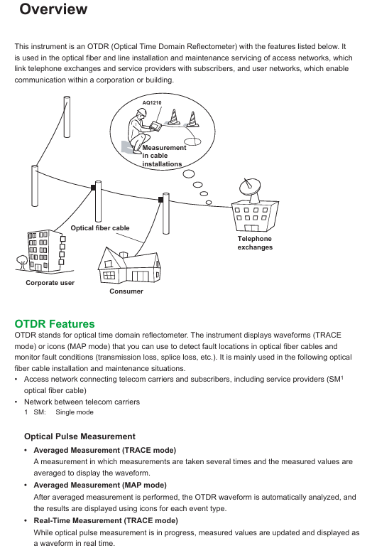
The AQ1210A, AQ1215A, AQ1210D, AQ1210E, AQ1215E, AQ1215F, and AQ1216F OTDR (Optical Time Domain Reflectometer) models are mainly used for the installation and maintenance of fiber optic lines in access networks and user networks. They can detect fiber optic fault locations, monitor transmission losses, fusion losses, and other parameters.
Core functions and operations
(1) OTDR core functions
Optical pulse measurement
Real time measurement (TRACE mode): The waveform is updated and displayed in real time during measurement, and events such as fusion loss and return loss can be monitored in real time. It supports adjusting parameters such as wavelength and distance range. In MAP mode, it will automatically switch to TRACE mode.
Average measurement:
TRACE mode: Take the average of multiple measurements to display the waveform, suitable for detecting weak events masked by noise.
MAP mode: Automatically analyze OTDR waveform after average measurement, display various event types with icons, support preset qualified/unqualified judgment conditions, and identify results with colors.
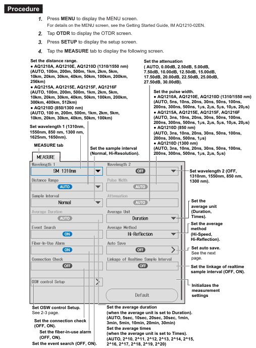
Multi wavelength measurement: A single operation can measure two wavelengths, 1310nm and 1550nm (or 850nm and 1300nm). First measure 1310nm (or 850nm), and then automatically switch to another wavelength.
Automatic check before measurement:
In use fiber optic alarm: detect whether there is communication light in the tested fiber optic cable to avoid affecting normal communication. If there is, a pop-up window will prompt whether to continue.
Connection check: Check the connection status between the device and the fiber optic cable, and prevent the OTDR port from emitting light if it is not connected correctly.
The data shows
TRACE mode (waveform display): The horizontal axis represents distance and the vertical axis represents loss level. The waveform can be scaled and moved, and the detected loss or reflection events (such as connectors, fusion points, bending points, etc.) are marked on the waveform.
MAP mode (icon display): Use different icons to display the loss and reflection of events such as connection points, curved sections, and open ends, arranged in order from the measurement starting point to the open end, clearly presenting the event location and distance.
data analysis
Trace mode: manually measure the distance between two points, fusion loss, return loss, etc. using the cursor and markers, supporting multiple measurement methods such as 4-point and 6-point markers.
Event analysis: Automatically detect all events in the waveform, display event types (such as positive/negative fusion loss, reflection, bending loss, etc.) and analysis results (distance, loss value, etc.), support manual editing of events (insertion, deletion, adjustment of marker position).
Qualified/unqualified judgment: preset thresholds for fusion loss, return loss, loss per kilometer, total loss, etc., automatically judge whether the measured value meets the standard. In TRACE mode, qualified items are marked in green and unqualified items are marked in red, and in MAP mode, color coded icons are used.
File function: Supports saving measurement data (. SOR format, including waveform, condition, event list), reports (. PDF format), system settings (. CFG format), screenshots (. BMP/. JPG format), can be stored in built-in memory (approximately 256MB) or USB devices, supports file copying, deletion, renaming, and report generation (can choose to include measurement conditions, waveform, event list, etc.).
(2) Practical tool functions
Light Source: Generate specific wavelength measurement light (such as AQ1210A supporting 1310nm, 1550nm) for fiber loss measurement or identification, and can output continuous light (CW) or modulated light (such as 270Hz, 1kHz).
Visible light source (/VLS option): 650nm wavelength visible light, used for visual detection of fiber breakage and inspection of multi-core fiber cores, supporting CW and 2Hz modulation modes.
Optical power meter (/SPM//HPM//PPM option)
Standard optical power meter (/SPM): measuring fiber loss or optical signal power of communication equipment in the wavelength range of 800-1700nm.
High power optical power meter (/HPM): Maximum measurement+27dBm high power, used for loss measurement in high-power scenarios.
PON optical power meter (/PPM): Simultaneously measure the optical power of passive optical networks (PON) at three wavelengths of 1310nm/1490nm/1550nm.
Support logging function, record short-term optical power stability, generate CSV format log files, calculate maximum, minimum, and average values.
Power checker (/PC option): detects the presence and power value of communication light in the tested fiber through the OTDR port, measuring wavelengths covering commonly used bands such as 1310nm and 1490nm.
Fiber end face inspection (/FST option): Connect the designated fiber end face inspection probe of Yokogawa, capture the status of the fiber end face and display it on the device screen. The image can be saved, and qualified/unqualified judgments can be made for the end face contact area, cladding area, and fiber core area respectively (in accordance with IEC 61300-3-35 standard).
Optical switch control: Connect a compatible optical switch box (such as AQ3550, 1 × 12 port configuration) to switch the measurement optical path in optical pulse measurement, and automatically switch the target channel during multi-core measurement.
(3) Application Function
OTDR Smart Mapper: Automatically repeat average measurements with different pulse widths in a single operation, analyze events automatically after completion, support MAP/TRACE mode display, MAP mode presents line events with icons, and TRACE mode combines multiple pulse width waveforms to improve measurement accuracy.
Multi Fiber Project: Manage the conditions and core information required for multi-core fiber measurement through "projects", support real-time measurement, average measurement, optical power measurement, fiber inspection probe operation, automatically save the measurement results of each fiber core to the corresponding folder, and avoid missing measurements.
Auto Loss Test: Two devices act as light sources and optical power meters respectively, automatically switching between 1310nm and 1550nm wavelengths to measure fiber loss; A single device can test fiber loss through loopback mode (OTDR port connected to OPM port).
Multicore Loss Test: Two devices are set as the master (optical power meter) and slave (light source), respectively. The master creates a project and transmits it to the slave. Through signal transmission of fiber optic synchronization information, the multi-core fiber loss is measured in batches, and testing can be resumed from the next core after interruption.
Advanced Analysis
Multi trajectory analysis: Load up to 4 waveforms and display comparisons simultaneously, with the ability to adjust the vertical position of each waveform.
Bidirectional trajectory analysis: Combining waveforms measured from both ends of the fiber, accurately measure the fusion loss of fibers with different levels of backscattering.
Differential trajectory analysis: Load two waveforms, display their difference waveforms, and measure the loss and distance of the difference waveforms with markers.
Segment analysis: Set starting point (S) and ending point (E) markers, measure the specified segment return loss and total loss, and support setting reference point (B) to calculate return loss.
(4) System setup and maintenance
System settings: configurable power-saving mode (screen brightness, automatic sleep), network (LAN/WLAN, supports remote control and data transmission), language, startup interface (TRACE/MAP/settings information), screen color (Color 1/Color 2/Black and White), operation lock (PIN code restricts laser output, mode switching, etc.), expiration date (expiration prompt for calibration or device lock).
Troubleshooting and Updating: Provides common troubleshooting solutions, error code explanations, supports firmware updates via USB, can restore factory settings (divided into "Reset Settings" and "Reset Settings and Delete User Files"), supports adding optional feature licenses.
Maintenance and storage: Regular mechanical and operational inspections should be conducted, and high temperature, humidity, and vibration environments should be avoided during storage. The battery pack should be operated according to the specifications in the dedicated manual.
Safety and usage regulations
Safety warning: When measuring, the light source port will light up. Do not disconnect the connected fiber optic cable to avoid direct light to the eyes, which may cause visual damage; When the fiber optic cable is not connected, the light source port cover needs to be closed.
Operating standards: Before use, read the manual thoroughly and strictly follow the steps to set measurement conditions and perform measurements; USB devices should not be unplugged or powered off during reading and writing to avoid data damage; Fiber optic connections need to be checked for correctness to prevent equipment or fiber optic damage.
Trademark statement: Microsoft, Google Chrome, Adobe, Bluetooth, etc. are registered trademarks of corresponding companies, omitted from the manual ® And TM symbol.
Summary of Key Tables
(1) Wavelength of various types of light sources (partial)
Model measurement of light wavelength
AQ1210A 1310nm、1550nm
AQ1215A 1310nm、1550nm
AQ1210D 1310nm、1550nm、850nm、1300nm
AQ1210E 1310nm、1550nm、1625nm
(2) File format description
Extension Description
. SOR optical pulse measurement results (including measurement/analysis conditions, waveforms, and event lists)
. PDF report format for current waveform or saved files
CFG device system settings (devices, connections, etc.)
Screenshot of. BMP/. JPG devices
Multiple waveforms measured simultaneously by SOZ
The waveform measured by the SMP Smart Mapper function
(3) Meaning of warning symbols
Symbol+Text Meaning
Warning: Operations/conditions and preventive measures that may cause serious or fatal injuries
CAUTION prompts operations/conditions and preventive measures that may cause minor injuries, equipment damage, or data loss
Note: Important information for correct device operation
- OMRON
- ABB
- General Electric
- EMERSON
- Honeywell
- HIMA
- ALSTOM
- Rolls-Royce
- MOTOROLA
- Rockwell
- Siemens
- Woodward
- YOKOGAWA
- FOXBORO
- KOLLMORGEN
- MOOG
- KB
- YAMAHA
- BENDER
- TEKTRONIX
- Westinghouse
- AMAT
- AB
- XYCOM
- Yaskawa
- B&R
- Schneider
- KONGSBERG
- NI
- WATLOW
- ProSoft
- SEW
- ADVANCED
- Reliance
- TRICONEX
- METSO
- MAN
- Advantest
- STUDER
- DANAHER MOTION
- Bently
- Galil
- EATON
- MOLEX
- DEIF
- B&W
- ZYGO
- Aerotech
- DANFOSS
- Beijer
- Moxa
- Rexroth
- Johnson
- WAGO
- TOSHIBA
- BMCM
- SMC
- HITACHI
- HIRSCHMANN
- Application field
- XP POWER
- CTI
- TRICON
- STOBER
- Thinklogical
- Horner Automation
- Meggitt
- Fanuc
- Baldor
- SHINKAWA
- Other Brands
- UniOP
- KUKA
- Iba
- Beckhoff
-
 Basler D90 96801 100 PCB Card
 -
 Basler XR2002F Voltage Regulator (110 VAC, 48-480 Hz)
 -
 Basler SR8A-2B14B3A Regulator
 -
 Basler 9561500100 Module
 -
 Basler DECS-400 BE1-11 System
 -
 Basler DECS-100-B15 Excitation Control
 -
 Basler SCP 210 Frequency Controller
 -
 Basler SR4A-2B15B3A Static Voltage Regulator
 -
 Basler BE1-32R Power Relay
 -
 Basler PIA2400-17GM Power Interface Adapter
 -
 Basler MVC 232 Manual Voltage Control Module
 -
 Basler SSR 32-12 Static Voltage Regulator
 -
 Basler 5MW AVR Generator Voltage Regulator
 -
 Basler VR63-4B Voltage Regulator
 -
 Basler DECS-100-A05 AVR for Engine Generator
 -
 Basler DECS-100-B15 Automatic Voltage Regulator
 -
 Basler BE1-32R Directional Power Relay
 -
 Basler BE1-87B Differential Relay
 -
 Basler UFOV 260A Protective Module
 -
 Basler 9-2614-02-100 PCB Rev M
 -
Basler DECS-100-B15 Digital AVR
-
 Basler 9284900103 PS DECS-400N
 -
 Basler D4N3H1U Intertie Protection
 -
 Basler DECS-100-B15 A15 AVR
 -
 Basler KR4F Voltage Regulator
 -
 Basler BE26434 T14 Transformer
 -
 Basler SR8A-2B15B3A Regulator
 -
 Westinghouse 774B472A12 AR Relay
 -
Basler DECS-100-B15 AVR
-
Basler XR2002F Regulator 110V
-
Basler SR125-E Static Regulator
-
 Basler SSR 125-12 Regulator
 -
 Basler MOC2599 Motor Pot
 -
 Basler BE1-DFPR Feeder Relay
 -
 Basler CBS 305 Current Boost
 -
 Basler BE1-25 AutoSync
 -
 Basler MVC 300 Voltage Control
 -
 Basler BE3-25A AutoSync
 -
 Basler KR7FF Static Regulator
 -
 Basler 90-49000-100 Regulator
 -
 Basler 880 kVA Dry Type Transformer Specs
 -
 Basler Electric BE1-25 Sync-Check Relay Specs
 -
 Basler SSR 125-12 Voltage Regulator Specs
 -
 Basler Electric BE1-851 Overcurrent Relay Review
 -
Basler Electric 149D930G02 Control Sub-Assembly
-
 Basler Electric BE1-81O/UT Frequency Relay Specs
 -
 Basler Electric BE1-51/27C Overcurrent Relay
 -
 Basler Electric 149D956G02 Industrial Component
 -
Basler Electric BE1-51A Overcurrent Relay Specs
-
 Basler Electric BE1-40Q Loss of Excitation Relay
 -
 Basler DECS-200 Excitation Control System
 -
 Basler DECS-200 Voltage Regulator 56-277V AC / 125V DC
 -
Basler BE1-87T Transformer Differential Relay
-
 Basler RDP-110-S1 Protection Relay
 -
 Basler BE1-700V Digital Protective Relay
 -
 Basler BE1-951 Overcurrent Protection System
 -
 Basler DECS-300 Digital Excitation Control
 -
 Basler DECS-200 Digital Excitation Control
 -
 Basler DECS-200-1C Excitation Control System
 -
Basler DECS-200-1L Digital Excitation Control
-
 Basler Electric BE1-GPS Generator Protection System
 -
Basler Electric DECS-200-1C Digital Excitation Controller
-
 Basler Electric DECS125-15 Excitation Control with Power Module
 -
 Basler Electric BE1-87G Differential Relay
 -
 Basler Electric BE1-11 Protection System I5A3M2P2N0EA00
 -
Basler Electric DECS-200-1C Excitation Control System
-
Basler Electric BE1-11g Generator Protection Relay
-
Basler Electric DECS 125-15-B2C1 V2.0.9 Excitation Control
-
 Basler Electric BE1-81O/UT3ED1JA7N2F Frequency Relay
 -
Basler Electric BE1-81O/UT3EE1YB7N1F Frequency Relay
-
 Basler Electric DECS-200-1L Digital Excitation Control System
 -
Basler DECS125-15-B2C1 Excitation Control
-
 Basler 9507900205 SSR Retrofit Voltage Regulator
 -
 Basler BE2000E Digital Voltage Regulator
 -
 Basler BE1-GPS Generator Protection System
 -
Basler DECS-250-CN1CN1N Digital Excitation Control
-
 Basler DGC-2020 Genset Controller
 -
 Basler BE1-81O UT3ED1LA7N0F Frequency Relay (Variant)
 -
 Basler BE1-81O UT3EE1YA9S0F Frequency Relay (Variant)
 -
Basler BE1-81O Over/Under Frequency Relay
-
Basler DECS125-15 Digital Excitation Control
-
Basler Electric BE1-951 Overcurrent Protection System
-
 Basler Electric BE1-700V Digital Protective Relay
 -
 Basler Electric APR63-5 Automatic Voltage Regulator
 -
Basler Electric BE1-851 Overcurrent Protection System
-
Basler Electric DECS-250-LN1SN1N Excitation Control
-
 Basler Electric BE1-87T Transformer Differential Relay
 -
Basler Electric DECS-200-1L Excitation Control System
-
 Basler Electric 9310300100 DECS-300 Excitation Control
 -
 Basler Electric SSE-N 125-4.5KW Shunt Exciter Regulator
 -
 Basler Electric DGC-2020HD-5NS1DNSBA Genset Controller
 -
Basler Electric BE1-81-O/UT3EE1JB7N1F Frequency Relay
-
Basler Electric BE1-81T1EE1WA0N1F Frequency Relay
-
 Basler Electric BE1-25M1EA6PN5R1F Sync-Check Relay
 -
 Basler Electric BE1-GPS Generator Protection System
 -
Basler Electric DECS-250-LN1SN1N Excitation Control Rev V
-
 Basler Electric DECS-250-CN2CN1N Excitation Control
 -
Basler Electric BE1-50/51B-207 Overcurrent Relay
-
Basler Electric DECS-300-C0N0 Excitation Control System
-
Basler Electric DECS-200 Digital Excitation Control System
-
Basler Electric DECS-250-LN1CN1N Excitation Unit
-
Basler Electric DECS-250 LN2SA1D Excitation Unit Specs
-
Basler Electric BE1-87T Transformer Relay Review
-
Basler Electric BE1-11 Protection System
-
Basler Electric BE1-GPS100-E4N1H1N Protection System
-
 Allen-Bradley 442G-MABH-R Safety Module
 -
 Beckhoff CX1030-0111 PLC Assembly Profile
 -
 FANUC IC693CPU364 PLC Module
 -
 Orange Denmark Type 200816 220 PLC Specs
 -
 OMRON C200H-SNT31 Sysmac PLC Module
 -
 Allen Bradley 20AB022A3AYNANC0 PowerFlex 70
 -
 OMRON C200HW-PCU01 Position Control Unit
 -
 ABB AO845A-eA Analog Output Module
 -
 OMRON CJ1M-CPU22 CPU Unit
 -
 Allen Bradley 100-E265ED11 Contactor
 -
 Honeywell 51304511-100 Interface Module
 -
 SOLEXY BXF3S0101N0018 Gateway Module
 -
 OMRON CJ2H-CPU65 CPU Unit
 -
 Automation Direct GS2-45P0 AC Drive
 -
 M68-2000 2-Axis Motion CNC Controller
 -
 OMRON CJ1M-CPU11 V3.0 PLC CPU Unit
 -
 OMRON CJ1W-NC413 4-Axis Positioning Controller
 -
 OMRON 3G2A3-PRO16 Programming Console HMI
 -
 Siemens 3VT8440-2AA04-2GA2 Molded Case Circuit Breaker
 -
 Siemens 3RT5045 Contactor Series
 -
 OMRON C200HS-CPU01-E SYSMAC PLC Controller
 -
 OMRON C500-NC103-E Positioning Control Unit
 -
 OMRON CJ1W-TC001 Temperature Control Unit


