
YOKOGAWA AQ7290 Series Optical Time Domain Reflectometer OTDR
YOKOGAWA AQ7290 Series Optical Time Domain Reflectometer OTDR
Product basic information
1. Product positioning and core applications
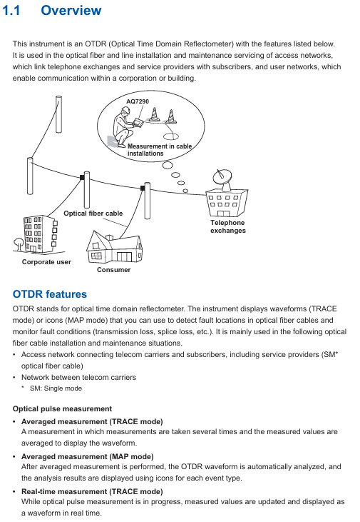
The AQ7290 series OTDR is a professional equipment used for fiber link detection. Its core function is to analyze the transmission loss, joint loss, fault location (such as breakage, bending) and other parameters of the fiber by emitting optical pulses and receiving reflected light. It is mainly used for:
Access network: Fiber optic installation and maintenance between telecommunications operators and users (mainly single-mode fiber optic).
Enterprise network: Fiber optic detection of internal communication networks within enterprises or buildings.
Long distance network: troubleshooting and performance monitoring of backbone fiber optic links between telecommunications operators.
2. Manual system and version information
Supporting documents: including Chinese specific documents (IM 739883-92Z1), European language safety manual (IM 00C01C01-01Z1), global contact list (PIM 113-01Z2), and communication interface manual (IM AQ7290-17EN) stored in device memory, which needs to be downloaded to PC for viewing.
Language code: In the manual number, "EN" represents English, "Z1" represents Chinese and other languages. Users can access it through the Yokogawa Customer Portal( https://myportal.yokogawa.com/ )Obtain the corresponding version.
Version iteration: The current version is the first edition in April 2025, and the content may change without prior notice due to product feature upgrades. The latest version should refer to the official website.
Trademark Statement: Mentioning brand trademarks such as Microsoft, Apple, Google, etc., omitted in the manual ® The TM symbol and other brand names belong to their respective holders.
Core functions and operating procedures
1. Basic measurement function (OTDR core)
(1) Optical pulse measurement mode
Support two core measurement modes to meet different scenario requirements:
Measurement mode, functional characteristics, applicable scenarios
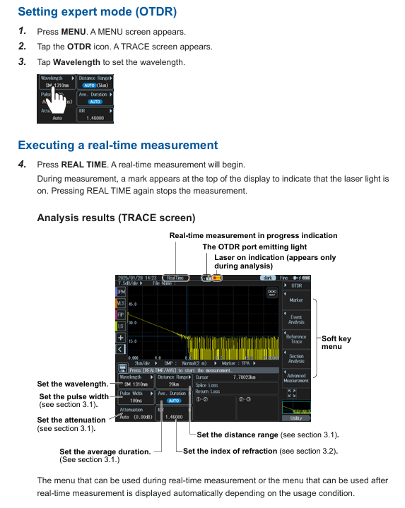
Average measurement (TRACE/MAP mode): Take the average of multiple measurements to reduce noise interference; Automatically analyze events after measurement, and switch between "TRACE" or "MAP" to accurately detect weak events (such as low loss connectors) and generate formal detection reports
Real time measurement (only available in TRACE mode) updates waveforms in real-time, supports dynamic adjustment of parameters such as wavelength and distance range, real-time monitoring during fiber installation, and quick troubleshooting of obvious faults
(2) Key measurement parameter settings
Wavelength: Different models support 1310nm, 1550nm, 1625nm, 1650nm, etc. For example, AQ7293F supports 1310/1550/1650nm, and AQ7293H supports 1310/1550/1625nm.
Distance range: Supports AUTO (automatic matching of fiber length) and manual setting of 100m-512km. It is necessary to select a range greater than the actual length of the fiber to ensure complete measurement.
Pulse width: Short pulses (3ns-30ns) are suitable for close range high-resolution measurement, while long pulses (1 μ s-20 μ s) are suitable for long-distance measurement, and can be manually set or automatically matched with a distance range.
Average frequency/duration: The average frequency supports 2 ¹⁰ -2 ² ⁰ times, with a duration of 5-30 minutes. The larger the frequency/duration, the higher the measurement accuracy but the longer the time consumption.
(3) Event analysis function
Automatically detect "events" (such as joints, fractures, bends) in fiber optic links and calculate key parameters:
Event types: including joint loss, reflection loss, bending loss, splitter loss, fiber optic endpoint (Fresnel reflection), etc., visually displayed in MAP mode through icons (such as "⊡" for joints and "■" for endpoints).
Analysis parameters: The joint loss threshold (0.01-9.99dB), reflection loss threshold (20-70dB), and fiber endpoint threshold (3-65dB) can be set. Events exceeding the threshold will be marked as "fault".
Manual adjustment: supports inserting/deleting events, editing event marker positions, and solving noise misjudgment or weak event missed detection problems.
2. Utility function
The device supports parallel use of multiple tools and can synchronously perform other detections during OTDR measurement, improving work efficiency:
Key parameters/options for the core purpose of tool functionality
Light Source fiber loss measurement, fiber identification output wavelength consistent with OTDR (such as 1310/1550nm), supports continuous light (CW) or modulated light (270Hz/1kHz/2kHz)
Visible light source (/VLS option) visually locates fiber breakpoints, checks multi-core fiber core sequence, fixed wavelength 650nm, supports CW or 2Hz modulation light
Optical power meter (/SPM//HPM option) measures optical signal power, fiber loss/SPM (standard): 800-1700nm,/HPM (high power): maximum+27dBm, supports logging (CSV format)
Power checker (/PC option) detects the presence of communication light in the fiber (to avoid interference) and measures wavelengths of 1310/1490/1550/1625/1650nm
Fiber end face detection probe (/FST option) can detect stains and scratches on the fiber end face. It supports USB or wireless connection and can determine the size of the fiber core/cladding/contact area (in accordance with IEC 61300-3-35 standard)
3. Advanced Application Features
Provide specialized solutions for complex scenarios, covering requirements such as multi-core fiber optics and long-term monitoring
(1) OTDR Smart Mapper
Function: Take multiple average measurements of the same wavelength using different pulse widths, automatically concatenate waveforms (narrow pulses for resolution at close range and wide pulses for coverage at far range), and generate link event maps.
Advantages: No need to manually switch pulse width, more accurate event localization for complex links (including spectrometers), and beginners can quickly understand the link structure.
(2) Multi Fiber Project
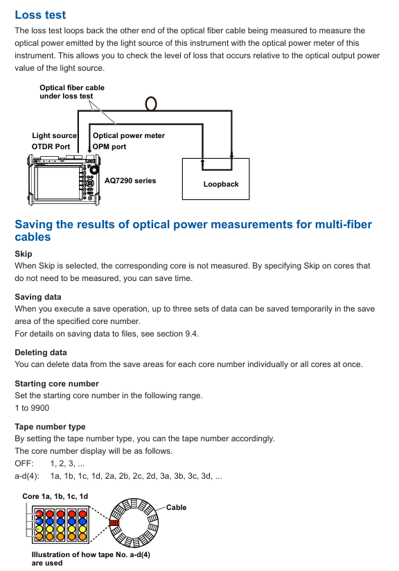
Project management: Package the measurement conditions (wavelength, distance range), number of cores (1-2000 cores), and core sequence (such as numbered 1a-1d) of multi-core optical fibers into a "project", supporting batch measurement and unified data management.
Batch operation: The screen displays the chip numbers in a table, and the measurement status is marked with colors (gray=stored data, green=qualified, red=unqualified) to quickly skip chip numbers that do not need to be measured and avoid omissions.
(3) Fiber optic monitoring (Schedule Measurement,/MNT option)
Timed measurement: Automatically perform OTDR measurement at set intervals (1-60min) and durations (1-120 days) to monitor changes in fiber loss (such as aging and external damage).
Data storage: Measurement data is automatically classified and stored by timestamp (SOR format waveform, CSV format log), supporting post analysis of fault occurrence time.
(4) Auto Loss Test/Multi Fiber Loss Test
Single core testing: Two devices work together, one as a light source and the other as an optical power meter, automatically switching wavelengths (1310/1550nm) to measure fiber loss.
Multi core testing: Synchronize multi-core fiber loss testing through the "master-slave mode", where the master device sends project configurations and the slave device performs measurements. The results are automatically transmitted back to the master device, making it suitable for batch acceptance of multi-core links.
(5) Advanced Analysis
Multi waveform comparison: Load up to 4 waveforms, support vertical offset adjustment, visually compare the loss differences of different time periods/links.
Bidirectional trajectory analysis: Combine waveforms measured from both ends of the fiber to accurately calculate the joint loss of fibers with different backscattering coefficients.
Differential trajectory analysis: Display the difference between two waveforms to quickly locate newly added loss points (such as fiber damage caused by later construction).
Data Management and Report Generation
1. Data storage and loading
Supporting media: Internal memory (approximately 1GB), USB storage device (USB 1.0/1.1/2.0), microSD card (SDC/SDHC/SDXC), up to 2 USB devices can be connected simultaneously.
File format:
SOR: Complies with Telcordia SR-4731 standard, stores waveform data and measurement conditions, and can be used for post analysis or imported into PC simulation software.
SET: Only stores measurement/analysis conditions for rapid reproduction of the same testing environment.
PDF: Generate reports for waveforms, event lists, and measurement conditions, supporting custom inclusion items such as company name and fiber optic identification.
CSV: Stores event data or optical power logs for easy secondary analysis using tools such as Excel.
BMP/JPG: Screenshots used to record on-site inspection results.
Auto Save: After the average measurement is completed, the data can be automatically saved, supporting storage by date or custom path classification to avoid data loss.
2. Report generation
Real time report: After the measurement is completed, the current waveform and event analysis results can be generated into PDF reports, including link maps, event lists, measurement conditions, and other information.
Batch report: Select multiple SOR files to automatically generate multi page PDF reports, support sorting by file name/date/ID, suitable for batch project acceptance.
Custom settings: tags such as company name, fiber ID, and tester can be added, and the report format supports comparing 1 waveform per page or 2 waveforms per page.
System settings and remote control
1. Basic system settings
Display settings: Supports screen themes (dark/light), brightness adjustment (4 levels, including OFF), wavelength/distance units (km/m), and decimal places (1-3).
Power management: In battery mode, automatic sleep mode can be set (1/5/10/30min no operation), LCD backlight can be turned off to extend battery life; The USB-AC adapter can maintain high brightness when powered.
Language and Shortcut Keys: Supports multiple languages (based on device suffix code), and can assign commonly used functions (such as saving and report generation) to the UTIL key for one click calling.
2. Network and Remote Control
Wired network (/LAN option): Supports 10BASE-T/100BASE-TX Ethernet, realizes PC remote control through TCP/IP protocol, and can transmit measurement data to the server.
Wireless network: Connect to a wireless LAN adapter (recommended model required), supporting access point mode (device as hotspot) or site mode (connected to existing WiFi), suitable for remote operation in Ethernet free scenarios.
LTE Dongle: Inserting an LTE adapter can connect remote devices through mobile networks, suitable for outdoor environments without WiFi/Ethernet.
Web server: PC browser input device IP address, can be accessed through "control mode" (remote device operation) or "view mode" (only view screen and download files), without the need to install dedicated software.
Safety and Maintenance
1. Safety regulations
Laser safety: When the equipment emits high-power laser (OTDR port, VLS port), it is forbidden to directly look at the port or disconnect the fiber during operation. If the fiber is not connected, the port cover should be covered to avoid eye damage.
Wiring safety: Before measurement, confirm that the fiber optic connection is correct (voltage line connected to voltage terminal, current line connected to current terminal). Do not touch the terminals during high voltage/high current output, and regularly check whether the terminals are overheated or loose.
Fault handling: If there is smoke, odor, or abnormal noise, immediately cut off the power and disconnect the load; When the output is automatically turned off (such as overload protection), troubleshoot and then turn it back on.
2. Maintenance and repair
Filter cleaning: Check and clean the rear air inlet filter every 3 months. If it is dirty, clean it with neutral detergent and let it dry naturally. Blockage can cause the equipment to overheat; The filter screen is damaged and needs to be replaced by contacting a Yokogawa dealer.
Self check function: Automatically perform self check (check fan, voltage/current range, internal circuit) when turned on, or manually trigger. If the self check fails, an error code will be displayed (such as E.901 indicating fan fault).
Calibration and replacement: It is recommended to calibrate once a year to ensure accuracy. Cooling fans (3 years), filters (1 year), and LCDs (approximately 40000 hours) should be replaced according to the recommended cycle, and maintenance should be carried out by Yokogawa certified personnel.
Storage conditions: When not in use for a long time, it should be stored in an environment with a temperature of -20~60 ℃ and a humidity of 10%~90% (no condensation), avoiding direct sunlight, vibration, or corrosive gases.
- OMRON
- ABB
- General Electric
- EMERSON
- Honeywell
- HIMA
- ALSTOM
- Rolls-Royce
- MOTOROLA
- Rockwell
- Siemens
- Woodward
- YOKOGAWA
- FOXBORO
- KOLLMORGEN
- MOOG
- KB
- YAMAHA
- BENDER
- TEKTRONIX
- Westinghouse
- AMAT
- AB
- XYCOM
- Yaskawa
- B&R
- Schneider
- KONGSBERG
- NI
- WATLOW
- ProSoft
- SEW
- ADVANCED
- Reliance
- TRICONEX
- METSO
- MAN
- Advantest
- STUDER
- DANAHER MOTION
- Bently
- Galil
- EATON
- MOLEX
- DEIF
- B&W
- ZYGO
- Aerotech
- DANFOSS
- Beijer
- Moxa
- Rexroth
- Johnson
- WAGO
- TOSHIBA
- BMCM
- SMC
- HITACHI
- HIRSCHMANN
- Application field
- XP POWER
- CTI
- TRICON
- STOBER
- Thinklogical
- Horner Automation
- Meggitt
- Fanuc
- Baldor
- SHINKAWA
- Other Brands
- UniOP
- KUKA
- Iba
- Beckhoff
-
 Basler D90 96801 100 PCB Card
 -
 Basler XR2002F Voltage Regulator (110 VAC, 48-480 Hz)
 -
 Basler SR8A-2B14B3A Regulator
 -
 Basler 9561500100 Module
 -
 Basler DECS-400 BE1-11 System
 -
 Basler DECS-100-B15 Excitation Control
 -
 Basler SCP 210 Frequency Controller
 -
 Basler SR4A-2B15B3A Static Voltage Regulator
 -
 Basler BE1-32R Power Relay
 -
 Basler PIA2400-17GM Power Interface Adapter
 -
 Basler MVC 232 Manual Voltage Control Module
 -
 Basler SSR 32-12 Static Voltage Regulator
 -
 Basler 5MW AVR Generator Voltage Regulator
 -
 Basler VR63-4B Voltage Regulator
 -
 Basler DECS-100-A05 AVR for Engine Generator
 -
 Basler DECS-100-B15 Automatic Voltage Regulator
 -
 Basler BE1-32R Directional Power Relay
 -
 Basler BE1-87B Differential Relay
 -
 Basler UFOV 260A Protective Module
 -
 Basler 9-2614-02-100 PCB Rev M
 -
Basler DECS-100-B15 Digital AVR
-
 Basler 9284900103 PS DECS-400N
 -
 Basler D4N3H1U Intertie Protection
 -
 Basler DECS-100-B15 A15 AVR
 -
 Basler KR4F Voltage Regulator
 -
 Basler BE26434 T14 Transformer
 -
 Basler SR8A-2B15B3A Regulator
 -
 Westinghouse 774B472A12 AR Relay
 -
Basler DECS-100-B15 AVR
-
Basler XR2002F Regulator 110V
-
Basler SR125-E Static Regulator
-
 Basler SSR 125-12 Regulator
 -
 Basler MOC2599 Motor Pot
 -
 Basler BE1-DFPR Feeder Relay
 -
 Basler CBS 305 Current Boost
 -
 Basler BE1-25 AutoSync
 -
 Basler MVC 300 Voltage Control
 -
 Basler BE3-25A AutoSync
 -
 Basler KR7FF Static Regulator
 -
 Basler 90-49000-100 Regulator
 -
 Basler 880 kVA Dry Type Transformer Specs
 -
 Basler Electric BE1-25 Sync-Check Relay Specs
 -
 Basler SSR 125-12 Voltage Regulator Specs
 -
 Basler Electric BE1-851 Overcurrent Relay Review
 -
Basler Electric 149D930G02 Control Sub-Assembly
-
 Basler Electric BE1-81O/UT Frequency Relay Specs
 -
 Basler Electric BE1-51/27C Overcurrent Relay
 -
 Basler Electric 149D956G02 Industrial Component
 -
Basler Electric BE1-51A Overcurrent Relay Specs
-
 Basler Electric BE1-40Q Loss of Excitation Relay
 -
 Basler DECS-200 Excitation Control System
 -
 Basler DECS-200 Voltage Regulator 56-277V AC / 125V DC
 -
Basler BE1-87T Transformer Differential Relay
-
 Basler RDP-110-S1 Protection Relay
 -
 Basler BE1-700V Digital Protective Relay
 -
 Basler BE1-951 Overcurrent Protection System
 -
 Basler DECS-300 Digital Excitation Control
 -
 Basler DECS-200 Digital Excitation Control
 -
 Basler DECS-200-1C Excitation Control System
 -
Basler DECS-200-1L Digital Excitation Control
-
 Basler Electric BE1-GPS Generator Protection System
 -
Basler Electric DECS-200-1C Digital Excitation Controller
-
 Basler Electric DECS125-15 Excitation Control with Power Module
 -
 Basler Electric BE1-87G Differential Relay
 -
 Basler Electric BE1-11 Protection System I5A3M2P2N0EA00
 -
Basler Electric DECS-200-1C Excitation Control System
-
Basler Electric BE1-11g Generator Protection Relay
-
Basler Electric DECS 125-15-B2C1 V2.0.9 Excitation Control
-
 Basler Electric BE1-81O/UT3ED1JA7N2F Frequency Relay
 -
Basler Electric BE1-81O/UT3EE1YB7N1F Frequency Relay
-
 Basler Electric DECS-200-1L Digital Excitation Control System
 -
Basler DECS125-15-B2C1 Excitation Control
-
 Basler 9507900205 SSR Retrofit Voltage Regulator
 -
 Basler BE2000E Digital Voltage Regulator
 -
 Basler BE1-GPS Generator Protection System
 -
Basler DECS-250-CN1CN1N Digital Excitation Control
-
 Basler DGC-2020 Genset Controller
 -
 Basler BE1-81O UT3ED1LA7N0F Frequency Relay (Variant)
 -
 Basler BE1-81O UT3EE1YA9S0F Frequency Relay (Variant)
 -
Basler BE1-81O Over/Under Frequency Relay
-
Basler DECS125-15 Digital Excitation Control
-
Basler Electric BE1-951 Overcurrent Protection System
-
 Basler Electric BE1-700V Digital Protective Relay
 -
 Basler Electric APR63-5 Automatic Voltage Regulator
 -
Basler Electric BE1-851 Overcurrent Protection System
-
Basler Electric DECS-250-LN1SN1N Excitation Control
-
 Basler Electric BE1-87T Transformer Differential Relay
 -
Basler Electric DECS-200-1L Excitation Control System
-
 Basler Electric 9310300100 DECS-300 Excitation Control
 -
 Basler Electric SSE-N 125-4.5KW Shunt Exciter Regulator
 -
 Basler Electric DGC-2020HD-5NS1DNSBA Genset Controller
 -
Basler Electric BE1-81-O/UT3EE1JB7N1F Frequency Relay
-
Basler Electric BE1-81T1EE1WA0N1F Frequency Relay
-
 Basler Electric BE1-25M1EA6PN5R1F Sync-Check Relay
 -
 Basler Electric BE1-GPS Generator Protection System
 -
Basler Electric DECS-250-LN1SN1N Excitation Control Rev V
-
 Basler Electric DECS-250-CN2CN1N Excitation Control
 -
Basler Electric BE1-50/51B-207 Overcurrent Relay
-
Basler Electric DECS-300-C0N0 Excitation Control System
-
Basler Electric DECS-200 Digital Excitation Control System
-
Basler Electric DECS-250-LN1CN1N Excitation Unit
-
Basler Electric DECS-250 LN2SA1D Excitation Unit Specs
-
Basler Electric BE1-87T Transformer Relay Review
-
Basler Electric BE1-11 Protection System
-
Basler Electric BE1-GPS100-E4N1H1N Protection System
-
 Allen-Bradley 442G-MABH-R Safety Module
 -
 Beckhoff CX1030-0111 PLC Assembly Profile
 -
 FANUC IC693CPU364 PLC Module
 -
 Orange Denmark Type 200816 220 PLC Specs
 -
 OMRON C200H-SNT31 Sysmac PLC Module
 -
 Allen Bradley 20AB022A3AYNANC0 PowerFlex 70
 -
 OMRON C200HW-PCU01 Position Control Unit
 -
 ABB AO845A-eA Analog Output Module
 -
 OMRON CJ1M-CPU22 CPU Unit
 -
 Allen Bradley 100-E265ED11 Contactor
 -
 Honeywell 51304511-100 Interface Module
 -
 SOLEXY BXF3S0101N0018 Gateway Module
 -
 OMRON CJ2H-CPU65 CPU Unit
 -
 Automation Direct GS2-45P0 AC Drive
 -
 M68-2000 2-Axis Motion CNC Controller
 -
 OMRON CJ1M-CPU11 V3.0 PLC CPU Unit
 -
 OMRON CJ1W-NC413 4-Axis Positioning Controller
 -
 OMRON 3G2A3-PRO16 Programming Console HMI
 -
 Siemens 3VT8440-2AA04-2GA2 Molded Case Circuit Breaker
 -
 Siemens 3RT5045 Contactor Series
 -
 OMRON C200HS-CPU01-E SYSMAC PLC Controller
 -
 OMRON C500-NC103-E Positioning Control Unit
 -
 OMRON CJ1W-TC001 Temperature Control Unit


