
How to maintain YOKOGAWA AQ7420 High Resolution Reflectometer?
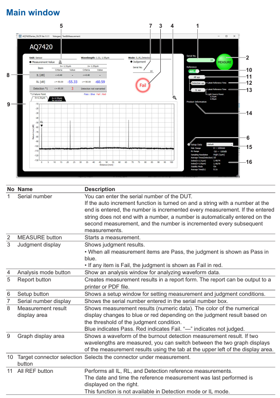
How to maintain YOKOGAWA AQ7420 High Resolution Reflectometer?
Instrument positioning and core applications
AQ7420 is a high-resolution reflectometer based on the principle of Time Domain Optical Coherence Tomography (TD-OCT) with built-in Michelson interferometer. Its core function is to measure three key parameters of optical devices through USB connection with the control PC
Optical Return Loss (RL): measures the return loss of fiber optic connectors, internal scratches, and device connection points, locates the position (with a maximum accuracy of 1 μ m) and intensity of reflection points.
Burnout Detection: Scan the distribution of return loss throughout the entire measurement range to identify abnormal reflection peaks such as fiber breakage and component defects.
Optical Insertion Loss (IL): measures the power attenuation of an optical signal passing through a Device Under Test (DUT) to evaluate the transmission performance of the device.
The instrument needs to be used in conjunction with a dedicated PC application, supporting local operation and TCP/IP remote control. The measurement results can be automatically graded, saved, and printed to meet the requirements of automated testing.

PC application installation and environmental requirements
1. Hardware and system requirements
Before installation, it is necessary to confirm that the control PC meets the following conditions, otherwise it may cause abnormal software operation or communication failure:
Project Requirements Explanation
The operating systems Windows 10 (32/64 bit) and Windows 11 do not support Windows XP/Vista/7/8 and tablet mode
Hardware configuration with at least 10MB of free hard disk space, USB interface free space for software installation and data storage, USB for instrument communication
Display resolution of 1024 × 768 pixels and above, 256 colors and above to ensure complete display of the operation interface, clear waveform diagram
The driver relies on NI-VISA 16.0 and above versions for communication between instruments and PCs, requiring VISA drivers. If not installed, it needs to be installed from the product CD first
2. Installation and uninstallation process
(1) Software installation steps
Preparation: Close the installed AQ7420 series software (if any) and log in to Windows with administrator privileges.
Start installation: Insert the product CD and run the path in English Application ARB-EDIT Setup. EXE (or enter the path through "Start Menu ->Run").
Driver installation: After completing the PC application installation as prompted, the FTDI CDM driver installation window will automatically pop up. Click "Extract → Next → I agree → Finish" in sequence to complete the driver deployment.
Start verification: After installation is complete, add the "AQ7420Series-OLCR" program under "Start Menu → YOKOGAWA", generate a shortcut icon on the desktop, double-click to start and enter the main interface.
(2) Uninstalling process (taking Windows 11 as an example)
Open "Control Panel ->Apps ->Installed Apps" and find "AQ7420Series'OLCR".
Click on the icon on the right side of the program, select "Uninstall", confirm and complete the uninstallation; If there are any remaining installation folders, they can be manually deleted (self built data needs to be backed up in advance).
(3) Connection exception handling
If the software prompts "Device Error" when starting, check:
Is the USB cable securely connected to the AQ7420 and PC.
Whether the VISA driver is installed properly (can be verified through NI MAX tool).
Whether the instrument power is turned on and whether the warm up is completed (it is recommended to perform reference measurements after preheating for 1 hour).
If you only want to view data without connecting the instrument, you can click "Viewer Mode" to enter the view mode.

Core functions and operating procedures
1. Preparation before measurement
(1) Instrument preheating and reference measurement
Preheating requirement: After starting up, the "Repeat Mode" should be turned on to run for 1 hour for preheating, to avoid temperature drift affecting measurement accuracy; After preheating, the reference measurement calibration system needs to be executed.
Reference measurement type:
Detection REF: The reference measurement for RL and burn detection requires the use of a dedicated main cable (Master Cord), with the open end of the main cable as the measurement starting point (0mm), to record the reference reflection intensity.
IL REF: Reference measurement of insertion loss, connect the main cable directly to the optical input port of AQ740023 sensor head, and record the reference optical power.
All REF: Simultaneously execute Detection REF and IL REF, suitable for scenarios where RL/burn detection and IL need to be measured simultaneously.
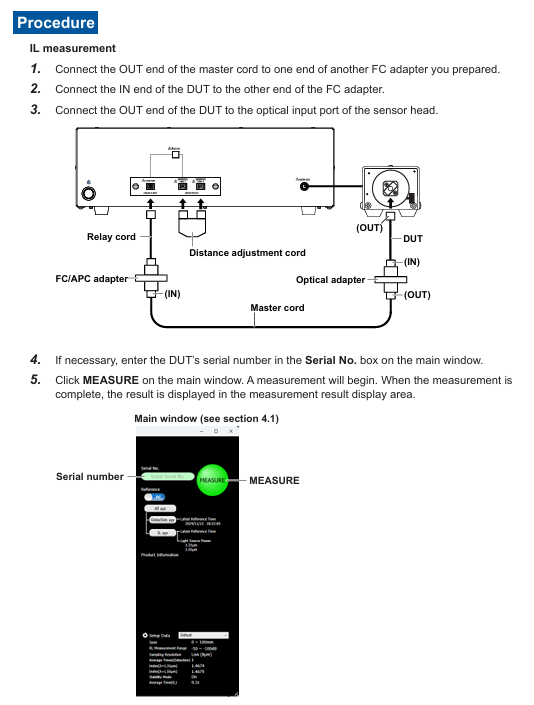
(2) Key hardware connections
When measuring different parameters, cables need to be connected according to specifications. The core components include the main cable (standard accessories, can be purchased separately), distance adjustment cable, relay cable, FC/APC adapter, and AQ740023 sensor head. The example connections are as follows:
RL/burn detection: AQ7420 test port → relay cable → FC/APC adapter → main cable → device under test (DUT), the open end of the main cable should be kept away from reflective objects (at least 100mm).
IL measurement: AQ7420 test port → relay cable → FC/APC adapter → main cable → DUT → AQ740023 sensor head, ensure that the connector end face is clean (dirt can cause excessive splicing loss, prompt "Under Range").
2. Measurement setup (Setup window)
Open the settings window through the "Setup" button on the main interface, configure measurement conditions, grading standards, data saving, and remote control parameters. The core settings are as follows:
(1) General settings
Operation mode: Supports three combination modes - "IL, RL, Detection" (single measurement of three types of parameters), "Detection" (only RL and burn detection), and "IL" (only IL).
Wavelength selection: main wavelength of 1.31 μ m, sub wavelength of 1.55 μ m (dual wavelength data can be measured simultaneously when sub wavelength needs to be enabled).
Start Position: Used for long-distance cable adjustment (optional accessory), input the distance compensation value displayed in the "Loopback Image" window to correct the measurement starting point offset.
(2) Measurement conditions
Scope of Settings/Option Description
Measurement distance (Span) from 0 to 100mm. The measurement time increases with distance and defaults to 100mm
RL measurement range -14.7~-85dB/-50~-100dB. The former is suitable for strong reflection scenarios, while the latter is suitable for weak reflection (such as deep loss)
The higher the sampling resolution of High (1 μ m)/Middle (4 μ m)/Low (8 μ m), the higher the measurement accuracy but the longer the time consumption
The average number of detections (Detection) is 1-16 times, and the more detections, the lower the noise
The refractive index (Index) of 1.0000~2.0000 is set according to the refractive index of the measured fiber (such as SM fiber 1.4674), which affects the accuracy of distance measurement
After turning on/off the Stability Mode, it automatically corrects the length drift of the main cable caused by changes in ambient temperature (0mm correction)
(3) Grading criteria (Analysis)
Set the qualified threshold for each parameter, and automatically compare and grade after measurement (blue "Pass", red "Fail"):
IL threshold: 0~40dB, supports setting display resolution (1/10~1/10000).
RL threshold: -120~-10dB, can limit the grading range (-10~110mm).
Burn detection threshold: -120~-10dB. Reflection peaks exceeding the threshold will be marked and counted on the waveform.
(4) Data saving settings
Storage path: Specify the data storage directory, enable "Auto Directory" to automatically create subfolders by "year/month/day".
File type: Waveform data supports CSV (numerical), JPG/BMP (image), measurement data (PS format) includes grading results, peak positions, and RL values, and dual wavelength data is merged and saved.
Auto Save: After enabling "File Save", save numerical data on a daily basis; The 'Waveform Save' supports modes such as' NG only auto save 'and' fully auto save 'to meet different testing needs.
3. Measurement operation process
(1) Reference measurement (taking PC polished DUT as an example)
RL/Burn Detection Reference (Detection REF):
Set the "Target Connector Selection" on the main interface to "PC", click on "Detection REF", and follow the prompts to connect the distance adjustment cable, relay cable, FC adapter, and PC polishing main cable (open end).
Click "OK" to perform the reference measurement. After completion, the command window will automatically close and record the reference reflection value at the 0mm starting point.
IL Reference (IL REF):
Click on "IL REF" on the main interface and connect the open end of the main cable to the optical input port of the AQ740023 sensor head.
Click "OK" to perform reference measurement, record the reference optical power, and use it for subsequent IL calculation (power difference after DUT insertion).
(2) DUT measurement
RL/Burn Detection Measurement:
Disconnect the main cable from the open end, connect the DUT (ensure the connector is clean and scratch free), and enter the DUT serial number (optional, supports automatic increment).
Click the "MEASURE" button on the main interface, and the instrument will scan the distribution of return loss within the measurement range. After completion, the RL value will be output in the "Measurement Result Display Area", and the waveform will display the burn detection peak.
IL measurement:
Connect the DUT in series between the main cable and AQ740023, click "Measure", and the instrument calculates the insertion loss of the DUT (the difference between the reference power and the measured power), and the result is displayed in real time (enabling "IL Realtime Mode" for continuous measurement).
4. Data analysis (Analysis window)
After the measurement is completed, click the "Analysis Mode" button on the main interface to enter the analysis window, which supports waveform detail viewing and marking analysis:
Waveform interaction: Drag and drop the mouse to pan the waveform, right-click or scroll to zoom in and out of a specific area, and use "DEFILT SCALE" to restore the default display scale.
Marking operation:
Click the "Marker Add" button to add markers on the waveform, and check the distance (mm) and RL value (dB) of the marker position.
Support calculating the distance difference and RL difference between two markers (such as A-B distance difference and RL difference) to assist in locating defect spacing.
Peak recognition: Reflection peaks that exceed the classification threshold are automatically marked, and the table displays the peak position, RL value, and classification result, making it easy to quickly locate outliers.
5. Data storage and printing
(1) Data saving
Manual Save: Click "SAVE" in the analysis window, and save the waveform data (CSV/JPG/BMP) according to the set path. The file name should include the date, time, and serial number (such as "PW20241115_103040-AA1. csv").
Auto Save: After enabling "Waveform Save", the measurement is automatically saved upon completion (only data classified as Fail is saved in NG mode to save storage space).
(2) Report printing
Click the "Report" button on the main interface to open the Windows print settings window, select the printer or "PDF" (generate PDF file).
The printed content includes instrument model, measurement time, set parameters, IL/RL/Detection results, waveform diagrams, and peak data, which are automatically summarized into a single page report for easy testing and archiving.
Remote control
1. Preparation for remote control
Hardware connection: The control PC is connected to the remote server via LAN, and the instrument is connected to the control PC via USB, ensuring that the network port (default 8889) is not blocked by a firewall.
Software settings: Enable "Remote Setting" in the PC application "Setup window → Remote Conditions", set the port number (consistent with the remote terminal), and enable "Local Key Display" to display the "Local Release Button" when connecting remotely.
2. Login and permission management
Login command: Remote terminal sends LOGIN<wsp>ID, Password. The default administrator ID/password is "reflectometer/reflectometer". After successful login, control the PC to display the "Remote" icon.
Permission classification:
Administrator: Can modify ID/password (IDWrite: ADMin<wsp>new ID, new password), create users (up to 5).
User: Only performs basic operations such as measurement and query results, and does not have permission to modify system settings.
Logout command: Send: LOGOut to disconnect the remote connection, or click on the control PC "Local Key" to force a switch to local control.
3. Core control commands
Remote control is based on TCP/IP protocol, with commands divided into "program messages" (control) and "query messages" (read). Examples of key commands are as follows:
Command group command example function
MAIN group: MAIN: EASure start/stop measurement
: MAIN: REF: ILREf Perform IL reference measurement
:MAIN:RESUlt:JUDGe? Query the overall judgment level result (0=Fail, 1=Pass)
SETUp group: SETUp: MODE<wsp>0 Set the operation mode to "IL, RL, Detection"
SETUP: EASure: STARt<wsp>20 Set measurement starting position 20mm
General command * IDN? Query instrument information (manufacturer, model, serial number, firmware version)
*RST resets instrument settings and stops all processes
The command supports abbreviations (such as SETUp, which can be abbreviated as SETU), is not case sensitive, the response message is in ASCII format, and the error command returns "Invalid Command".
Precautions and Maintenance
1. Measurement accuracy guarantee
Environmental control: IL measurement should be conducted in a constant temperature environment (temperature fluctuation within ± 1 ℃) to avoid direct blowing of instruments and cables by air conditioning; The cable layout needs to be fixed to reduce position deviation caused by vibration.
Cable maintenance: The main cable and sensor head connector need to be cleaned regularly (using specialized fiber optic cleaning paper). Scratches on the end face can cause measurement errors and need to be replaced in a timely manner.
Wavelength influence: When measuring SM fiber (1.31 μ m zero dispersion) at a wavelength of 1.55 μ m, it is affected by dispersion, resulting in low long-range reflection values; DSF fiber (1.55 μ m zero dispersion) does not have this problem, but 1.31 μ m measurement is affected by dispersion.
2. Troubleshooting
Possible causes and solutions for error phenomena
Refer to the measurement prompt for "Under Range" connector end face dirt/scratches, poor adapter coupling, clean end face (refer to section 2.5 of the manual), check adapter installation, replace damaged cables
Excessive waveform noise, strong total reflected light from DUT, improper measurement range setting, terminal matching with DUT end to reduce noise, switch RL measurement range to "-50~-100dB"
Remote connection failed due to port number mismatch, firewall interception, VISA driver exception. Confirmed port consistency, closed firewall, and reinstalled NI-VISA driver
3. Software maintenance
Version check: Check the PC application version (such as Ver. 1.1.0) through "Help → About", and update patches can be downloaded from the official website.
Open source software instructions: The installation directory "OLCR_Sttribution. txt" contains open source software license information and must be used in accordance with the corresponding terms.
- ABB
- General Electric
- EMERSON
- Honeywell
- HIMA
- ALSTOM
- Rolls-Royce
- MOTOROLA
- Rockwell
- Siemens
- Woodward
- YOKOGAWA
- FOXBORO
- KOLLMORGEN
- MOOG
- KB
- YAMAHA
- BENDER
- TEKTRONIX
- Westinghouse
- AMAT
- AB
- XYCOM
- Yaskawa
- B&R
- Schneider
- Kongsberg
- NI
- WATLOW
- ProSoft
- SEW
- ADVANCED
- Reliance
- TRICONEX
- METSO
- MAN
- Advantest
- STUDER
- KONGSBERG
- DANAHER MOTION
- Bently
- Galil
- EATON
- MOLEX
- DEIF
- B&W
- ZYGO
- Aerotech
- DANFOSS
- Beijer
- Moxa
- Rexroth
- Johnson
- WAGO
- TOSHIBA
- BMCM
- SMC
- HITACHI
- HIRSCHMANN
- Application field
- XP POWER
- CTI
- TRICON
- STOBER
- Thinklogical
- Horner Automation
- Meggitt
- Fanuc
- Baldor
- SHINKAWA
- Other Brands
- UniOP
- KUKA
- Iba
-
 Wurth Elektronik 74271132 WE-STAR-TEC Snap Ferrite
 -
 Woodward 9907-165 Digital Turbine Control Module
 -
 DS1230Y-150+ 256Kb Non-Volatile SRAM Maxim Integrated
 -
 ZIPPE MWS10/A Industrial Weighing Transmitter Module
 -
 ZNYX ZX370 Series Fast Ethernet PCI Adapter
 -
 Vortran KDL-1230 Precision Medical Control
 -
 VWR Scientific Model 3000 Lab Equipment
 -
 Wagner+Grimm CH-6102 ETUI1500 Transformer Technical Specs
 -
 Wago MCS 231-302/037-000 Male Connector
 -
 Wago VDE0611 Series Rail-Mounted Terminal Blocks
 -
 Warner Electric ERS-198 1005-05-001 Electrically Released Brake
 -
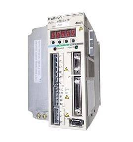
 Yaskawa SGDH-01AE Sigma II Servo Driver
 -
 Omron 3G3HV-A4022-CE Inverter
 -
 Omron NT625C-ST152 Color Touch HMI
 -
 Parker Parvex NX310EAKR7001 NX Series Servo Motor
 -
 UniOp TCP10G-04-0245 Industrial HMI
 -
 Yaskawa SGDH-04AE Servo Driver 200V 400W
 -
 Presstech 7612-099Z-01 PLC Control Board
 -
 Yaskawa SGDH-10DE Servo Driver 400V 1kW
 -
 Landis Gyr PCA1 M35M4 CPU Controller
 -
 MICREX-F FLT-ASFKA PLC Loader with RS232 Cable
 -
 ABB Bailey INNIS21 Network Interface Module
 -
 Omron Sysmac CV500-SNT31 SYSMAC LINK Unit
 -
 Parker Hannifin HID2CS/S4 HiDrive Servo Driver
 -
 Pogliano Busmar PPeF 224541Z0HAC 250A Switch
 -
 GE Fanuc A16B-3300-003 Series 16-i Main Board
 -
 BLQ63M30 Brushless Servo Motor High Precision Motion Control
 -
 YASKAWA SGDH-08AE-S-OY Servopack Servo Drive Motion Control
 -
 OMRON C200H-RT201 Remote I/O Unit PLC Communication Module
 -
 PARKER HPD2S2N Servo Driver Industrial Motion Controller
 -
 SIEMENS 6AV3617-1JC00-0AX1 HMI Operator Panel Interface
 -
 KEB E3.SM.001.4400 Servomotor
 -
 Omron SCY-M1-PRO-51C SYSMAC Programming Console
 -
 ABB SACE TMAX T4 S 160 4 Pole Circuit Breaker
 -
 Omron CS1G-CPU44-EV1 PLC CPU Unit
 -
 ABB SACE PR212/P Electronic Trip Unit
 -
 Mitsubishi HC-SFS524K AC Servo Motor
 -
 Parker S.B.C. HPD2S1N Electronics Servo Driver
 -
 Yaskawa SGMPH-08A1A41 Sigma II Servo Motor
 -
 Omron FQ2-S25050F Smart Camera Vision System
 -
 Omron C120-LK202-EV1 Host Link Unit RS-422C Interface
 -
 23.SM.000.3400 PLC KEB Servo Motor Industrial Control System
 -
 Biesse Rover CNI PLC 2153 030 7146.30 Industrial Control Unit
 -
 OMRON ME5614C Industrial Modem 56000bps V.90 Communication
 -
 SCHNEIDER BCH16HF07332A5C2 Servo Motor High Precision Control
 -
 ANFX-P130F-1GL3-33 Precision Gearbox Industrial Transmission
 -
 Beckhoff CX5020-0110 Embedded PC PLC
 -
 Schneider PowerLogic P5U20 Protection Relay Easergy
 -
 Siemens 6ES5 466-3LA11 Simatic Analog Input Module
 -
 Tex Computer TEB0055 77037 Industrial Terminal
 -
 Audiotel Engineering 0802P1I8000E Industrial Interface Module
 -
 ELAU DB-5 Distribution HW 5104 Servo System
 -
 Touchstar 10K TS10KCC0CEMP Industrial Touch Panel
 -
 Beckhoff CX2030-0125 Embedded PC PLC
 -
 Parker Hannifin HID5CS/S4 HIDRIVE 5A Servo Drive
 -
 Yaskawa ACE-P300-TH5 Servo Drive with Profibus
 -
 Omron Sysmac SCY-P0 13E Sequencer Controller
 -
 Saia Burgess PCD4.M120 PCD4.M12 Central Controller
 -
 Schneider Electric TSX3722101 Modicon Micro PLC
 -
 Siemens Micromaster 440 6SE6440-2AD25-5CA1 Inverter
 -
 SICK DL50-P1123 Distance Sensor
 -
 Yaskawa SGDH-04AE-OY Servo Driver 200V 400W
 -
 Cincinnati Milacron 3-542-1203A Circuit Board Module
 -
 Allen-Bradley 1756-EN2T EtherNet/IP Communication Module
 -
 OMRON CS1H-CPU66-V1 Programmable Logic Controller
 -
 ABB SACE TMAX S6N 630 Molded Case Circuit Breaker
 -
 Weidmuller IE-SW-VL16-16TX 16-Port Ethernet Switch
 -
 Schneider PowerLogic CM4250 Circuit Monitor
 -
 Sacmi IDPM IDMP1.A SMC 085.16.982 Control
 -
 Omron C120-LK202-EV1 Host Link Unit
 -
 Omron FQ2-S15050F Smart Camera Vision System
 -
 OMRON CJ1G-CPU44H Programmable Logic Controller
 -
 SIEMENS KTP600 HMI 6AV6 647-0AD11-3AX0 Touch Panel
 -
 OMRON CS1G-CPU45H EV1 Programmable Logic Controller
 -
 Omron C200HG PLC System C200H-ID212 C200H-OC226
 -
 ROBOSYSTEM IOG4AX-HD-100 IOG-HD Motion Controller
 -
 Datalogic SG4-S3-080-PP-W Safety Light Curtain
 -
 Omron NS12-TS01B-V2 Interactive Display
 -
 Esto Electronic E.CGT-405-42TE PLC Rack
 -
 Siemens 7ED62 Static Three Phase Counter
 -
 Oemer QCAVS 100 LBE AC Square Frame Servo Motor
 -
 Schneider Electric TM262M25MESS8T Motion Controller
 -
 Eaton Moeller MFD-CP8-ME Power Supply
 -
 Pro-face PL-5700T1-24VDC Industrial Panel PC
 -
 GE Fanuc IC693APU300J High Speed Counter
 -
 Fuji Electric Micrex-F FPU080S PLC Module
 -
 Automation Direct GS2-45P0 AC Drive
 -
 Omron 3G3MV-C4015 V1000 Inverter
 -
 Vacon NXI01055A2T0CSS Industrial Inverter
 -
 Saia Burgess PCD4.M240 Central Controller Module
 -
 Yaskawa SGDH-10DE Sigma II Servo Drive
 -
 Stober EK501USOM140 Servo Motor and Drive
 -
 SCE M68-2000/4 CNC Controller and I/O Board
 -
 Omron SP10-PR001-V1 PLC Programming Console Specs
 -
 VACON NXI01055A2T0CSSA Industrial AC Drive
 -
 OMRON SYSMAC SCY-P1 Sequencer Controller PLC
 -
 SEL-2440 DPAC Discrete Programmable Controller
 -
 BIVIATOR CI3098 CPU Encoder Module Industrial Control Unit
 -
 Siemens 6FC5371-0AA10-0AA2 SINUMERIK NCU 710.2
 -
 KOLLMORGEN SERVOSTAR S70601-NA High Performance Servo Drive
 -
 OMRON C200HW-PCU01 Fastnet PCMCIA LAN Communication Unit
 -
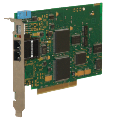 ibaFOB-2io-D Two-Channel Fiber Optic Input Output Card
 -
 ibaFOB-4io-D Four-Channel Fiber Optic Input Output Card
 -
 ibaFOB-io-S Single-Channel Fiber Optic Input Output Card
 -
 ibaFOB-4io-S Four-Channel Fiber Optic Input Output Card
 -
 ibaFOB-4o Four-Channel Fiber Optic Output Interface Card
 -
 ibaFOB-4i-S Enhanced Four-Channel Fiber Optic Input Card
 -
 ibaFOB-4i Four-Channel Fiber Optic Input Interface Card
 -
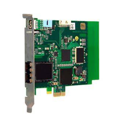
 ibaFOB-io Fiber Optic Interface Card for iba Systems
 -
 SM128V VMEbus Interface Card for Industrial Data Acquisition
 -
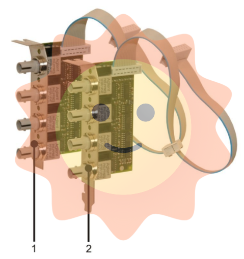
 ibaLink-SM-128V-i-2o VMEbus Fiber Optic Interface Board
 -
 GE Fanuc IC693MDL632 125V DC Input Module 8 Points
 -
 GE Fanuc IC693MDL241 24V AC/VDC Input Module 16 Points
 -
 GE Fanuc IC693MDL240 120V AC Input Module 16 Points
 -
 GE Fanuc IC693MDL231 240V AC Isolated Input Module
 -
 GE Fanuc IC693MDL230 120V AC Isolated Input Module
 -
 GE Fanuc IC693MDL654 5/12 VDC 32-Point Input Module
 -
 GE Fanuc IC693MDL653 24 VDC 32-Point Input Module
 -
 GE Fanuc IC693MDL648 48 VDC 16-Point Input Module
 -
 GE Fanuc IC693MDL646 24 VDC 16-Point Input Module
 -
 GE Fanuc IC693MDL634 24 VDC Input Module 8 Points
 -
 GE IM 3100 D 1007722 Control Module
 -
 GE IM0146B Industrial Circuit Board
 -
 GE IM0059E0-10070 Interface Board
 -
 GE IM0094C Industrial Control Board
 -
 GE IC200PNS002-AB VersaMax PROFINET Scanner
 -
 GE F650BFBF1G0HI Feeder Protection Relay
 -
 GE TPR5616NRHC Protection Relay


