
How to troubleshoot the YOKOGAWA CA500/CA550 multifunctional process calibrator?
YOKOGAWA CA500/CA550 Multi functional Process Calibration Instrument
Instrument positioning and core use
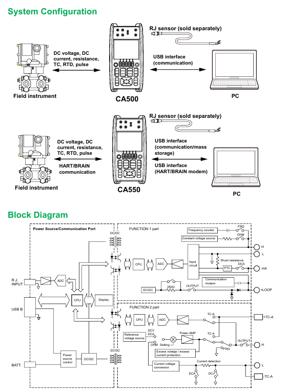
CA500/CA550 is a portable multifunctional process calibrator, whose core function is to provide standard signal generation and parameter measurement for field instruments such as transmitters, sensors, and controllers. It supports synchronous operation of "generation measurement" and achieves high efficiency and accuracy in instrument calibration. The core difference between the two lies in the addition of HART/BRAN communication function in CA550, which can directly interact with smart meters, read device information, perform loop testing, and output adjustment.
Core functions and technical parameters
1. Overview of core functions
CA500/CA550 supports 6 types of signal generation and 6 types of parameter measurement, covering mainstream calibration requirements in industrial sites. The specific functional comparison is as follows:
Function type supports signal (CA500/CA550 universal) CA550 additional functions
Signal generation includes DC voltage (100mV~30V), DC current (20mA/4-20mA), resistance (400 Ω/4000 Ω), thermocouple electromotive force, RTD simulation, frequency/pulse (1Hz~50kHz/CPM), HART/BRAN communication signal superposition, program scanning (20 calibration points), and automatic data grading (Pass/Tail)
Parameter measurement: DC voltage (100mV~50V), DC current (50mA), resistance (400 Ω/4000 Ω), thermocouple temperature, RTD temperature, frequency/pulse counting. HART device information reading (label, range, diagnostic data), BRAIN device model/serial number reading, calibration data CSV export
Scanning function includes linear scanning (0%~100% linear variation), step scanning (equidistant step output), program scanning (CA500 supports 10 points), program scanning supports 20 points, can associate calibration object information (model, serial number, label), automatically save scanning data and grading results
Data management manually saves 100 pieces of data, scanned data is automatically saved (in CA500 dedicated format), data is saved in CSV format (supporting comma/semicolon/tab separation), USB storage is exported, and folders are automatically classified by "year/month/day"
2. Key technical parameters
Accuracy level: DC voltage ± 0.01% FS, DC current ± 0.01% FS, resistance ± 0.01% FS, temperature (thermocouple) ± 0.1 ℃ (K-type, 0~1000 ℃).
Resolution: DC voltage of 100mV with a range of 1 μ V, DC current of 20mA with a range of 1 μ A, resistance of 400 Ω with a range of 0.01 Ω, and frequency of 500Hz with a range of 0.01Hz.
Output capability: DC current output with a maximum load of 20V (4-20mA range), resistance output with a permissible measured current of 0.1-3mA (400 Ω range).
Communication interface: USB Type B (supports remote control and CA550 data export), HART/BRAN communication port (CA550 specific, stacked on 4-20mA loop).
Operation process and core scenarios
1. Basic operations: Signal generation and measurement
Taking "4-20mA current generation+measurement" as an example, explain the standard operating procedure:
(1) Signal occurrence setting (Function 2)
Function selection: Press the Function 2 key, use the directional keys to select mA (current), and press ENTER to confirm.
Range setting: Press the RANGE key, select 4-20mA (default 0%=4mA, 100%=20mA), and press ENTER to confirm.
Parameter adjustment: Set the output value (such as 8mA) through the numeric keys or UP/DOWN keys, press the OUTPUT ON/OFF key to start the output, and the screen will display "OUTPUT: ON".
Scanning function (optional): If step output is required, enter SETUP → Sweep Setup → Step Sweep, set the interval time (such as 10 seconds) and repeat mode (ON/OFF), press the SWEEP key to start step scanning.
(2) Parameter measurement settings (Function 1)
Function selection: Press the Function 1 key, use the directional keys to select mA (current), and press ENTER to confirm.
Range setting: Press the RANGE button, select 50mA (covering 4-20mA measurement requirements), and press ENTER to confirm.
Loop power supply (optional): If measuring a two-wire transmitter, press the LOOP POWER button, and the instrument will output 24VDC loop power while measuring the transmitter output current.
Data reading: The screen displays the measured values in real-time, and pressing the AVERAGE key can view the 5 times moving average, maximum value, and minimum value.
2. Advanced scenario 1: Temperature calibration (thermocouple/RTD)
(1) Thermocouple temperature occurrence (simulating K-type thermocouple)
Function selection: Function 2 → TC SRC (thermocouple occurrence), select K type with the RANGE key, press ENTER to confirm.
Terminal settings: Go to SETUP → Temperature Setup → TC Terminal, select TC-B (banana plug, supports external reference compensation), set TC-B RJC to ON (enables reference compensation).
Temperature setting: Enter the target temperature (such as 200 ℃) through the numerical keys, press OUTPUT ON/OFF to start the output, and the screen will synchronously display the corresponding thermoelectric potential (such as 8.137mV, in accordance with ITS-90 standard).
- OMRON
- ABB
- General Electric
- EMERSON
- Honeywell
- HIMA
- ALSTOM
- Rolls-Royce
- MOTOROLA
- Rockwell
- Siemens
- Woodward
- YOKOGAWA
- FOXBORO
- KOLLMORGEN
- MOOG
- KB
- YAMAHA
- BENDER
- TEKTRONIX
- Westinghouse
- AMAT
- AB
- XYCOM
- Yaskawa
- B&R
- Schneider
- KONGSBERG
- NI
- WATLOW
- ProSoft
- SEW
- ADVANCED
- Reliance
- TRICONEX
- METSO
- MAN
- Advantest
- STUDER
- DANAHER MOTION
- Bently
- Galil
- EATON
- MOLEX
- DEIF
- B&W
- ZYGO
- Aerotech
- DANFOSS
- Beijer
- Moxa
- Rexroth
- Johnson
- WAGO
- TOSHIBA
- BMCM
- SMC
- HITACHI
- HIRSCHMANN
- Application field
- XP POWER
- CTI
- TRICON
- STOBER
- Thinklogical
- Horner Automation
- Meggitt
- Fanuc
- Baldor
- SHINKAWA
- Other Brands
- UniOP
- KUKA
- Iba
- Beckhoff
-
 Basler DECS-200-2L Digital Excitation Control
 -
 Basler BE1-47N Voltage Phase Sequence Relay
 -
 Basler AEC63-7 Analog Excitation Controller 220-277V
 -
 Basler BE1-50/51B-107 Overcurrent Relay
 -
 Basler Electric BE1‑32R BE1‑E1P‑BON0F Protective Relay
 -
 Basler BE1-25 Solid State Time Overcurrent Relay M1EA6PA5S1F
 -
 Basler MVC 232 Manual Voltage Control Module 90 37000 103 60VAC 55VDC
 -
 Basler RAL6144-16GM Racer GigE Line Scan Camera
 -
 Basler SSR 63-12 Static Voltage Regulator
 -
 Basler BE1-51A Overcurrent Relay
 -
 Basler BE1-87T Solid State Protective Relay
 -
 Basler SR4A2B01B3A Static Voltage Regulator
 -
 Basler SSR 32-12 Static Voltage Regulator
 -
 Basler TRR00696 Transformer 1KVA 115V
 -
 Basler DECS-100-B15 AVR Replacement
 -
Basler BE1-27 Under-Voltage Relay
-
 Basler ACA2000-50GM Interface Module
 -
 Basler AEC63-7 Analog Excitation Controller
 -
 Basler PRS 250 Veri-Sync Relay
 -
 Basler SR4A-2B15B3A Static Voltage Regulator
 -
Basler BE1-32R Power Relay
-
Basler SR8A-2B06B3E Static Voltage Regulator
-
Basler BE1-81 O/U Frequency Relay
-
 Basler BE1-51A-K2E-W6M-B1N0F Overcurrent Relay
 -
Basler BE1-851 Overcurrent Relay G3A1S1 – 48-125V AC/DC
-
 Basler BEI-51 Overcurrent Relay – NSN 5945-01-293-2363
 -
Basler Electric L301KC Protective Relay – L301KC
-
 Basler DECS-100-B15 Automatic Voltage Regulator – Generator AVR
 -
 Basler SR4A-2B15B3A Static Voltage Regulator – SR4A2B15B3A
 -
 Basler UF 312 Under Frequency Protective Module – 9094700100
 -
Basler Electric MVC 232 Manual Control Module – 60VAC 55VDC 20A
-
Basler PRS 250 Veri-Sync Relay – Generator Synchronizing Relay
-
 Basler DECS-100-A05 Digital Regulator Review
 -
 Basler AEM-2020 Analog Expansion Module Specs
 -
 Basler DECS-100-B15 Digital Excitation Specs
 -
Basler Electric 9125600106 Regulator Component
-
Basler BE1-51A-K1E-W6M-B1N0F Overcurrent Relay
-
 Basler MVC-301 MVC 300 Excitation Controller
 -
 Basler SSR 32-12 Static Voltage Regulator
 -
 Basler 9-2849-00-101 Control Module
 -
Basler BE1-51A Overcurrent Relay
-
 Basler BE1-51/27R Overcurrent Relay
 -
 Basler BE1-51 Overcurrent Relay
 -
 Basler SR8A-2B15B3A Static Voltage Regulator
 -
 Basler BE32965001 Transformer and Timer Board
 -
 Basler 9174700100 EL200-7 Excitation Limiter
 -
 Basler BE2000E AVR Voltage Regulator
 -
Basler BE1-87G Differential Relay
-
 Basler BE21834001 Generator Control Module
 -
Basler DECS-100-B15 AVR
-
 Basler D90 96801 100 PCB Card
 -
 Basler XR2002F Voltage Regulator (110 VAC, 48-480 Hz)
 -
 Basler SR8A-2B14B3A Regulator
 -
 Basler 9561500100 Module
 -
 Basler DECS-400 BE1-11 System
 -
 Basler DECS-100-B15 Excitation Control
 -
 Basler SCP 210 Frequency Controller
 -
Basler SR4A-2B15B3A Static Voltage Regulator
-
Basler BE1-32R Power Relay
-
 Basler PIA2400-17GM Power Interface Adapter
 -
 Basler MVC 232 Manual Voltage Control Module
 -
 Basler SSR 32-12 Static Voltage Regulator
 -
Basler 5MW AVR Generator Voltage Regulator
-
 Basler VR63-4B Voltage Regulator
 -
Basler DECS-100-A05 AVR for Engine Generator
-
Basler DECS-100-B15 Automatic Voltage Regulator
-
Basler BE1-32R Directional Power Relay
-
Basler BE1-87B Differential Relay
-
 Basler UFOV 260A Protective Module
 -
 Basler 9-2614-02-100 PCB Rev M
 -
Basler DECS-100-B15 Digital AVR
-
 Basler 9284900103 PS DECS-400N
 -
 Basler D4N3H1U Intertie Protection
 -
 Basler DECS-100-B15 A15 AVR
 -
 Basler KR4F Voltage Regulator
 -
 Basler BE26434 T14 Transformer
 -
 Basler SR8A-2B15B3A Regulator
 -
 Westinghouse 774B472A12 AR Relay
 -
Basler DECS-100-B15 AVR
-
Basler XR2002F Regulator 110V
-
Basler SR125-E Static Regulator
-
Basler SSR 125-12 Regulator
-
Basler MOC2599 Motor Pot
-
 Basler BE1-DFPR Feeder Relay
 -
 Basler CBS 305 Current Boost
 -
Basler BE1-25 AutoSync
-
Basler MVC 300 Voltage Control
-
 Basler BE3-25A AutoSync
 -
 Basler KR7FF Static Regulator
 -
Basler 90-49000-100 Regulator
-
 Basler 880 kVA Dry Type Transformer Specs
 -
Basler Electric BE1-25 Sync-Check Relay Specs
-
 Basler SSR 125-12 Voltage Regulator Specs
 -
 Basler Electric BE1-851 Overcurrent Relay Review
 -
Basler Electric 149D930G02 Control Sub-Assembly
-
 Basler Electric BE1-81O/UT Frequency Relay Specs
 -
 Basler Electric BE1-51/27C Overcurrent Relay
 -
 Basler Electric 149D956G02 Industrial Component
 -
Basler Electric BE1-51A Overcurrent Relay Specs
-
 Basler Electric BE1-40Q Loss of Excitation Relay
 -
Basler DECS-200 Excitation Control System
-
 Basler DECS-200 Voltage Regulator 56-277V AC / 125V DC
 -
Basler BE1-87T Transformer Differential Relay
-
 Basler RDP-110-S1 Protection Relay
 -
 Basler BE1-700V Digital Protective Relay
 -
 Basler BE1-951 Overcurrent Protection System
 -
 Basler DECS-300 Digital Excitation Control
 -
 Basler DECS-200 Digital Excitation Control
 -
 Basler DECS-200-1C Excitation Control System
 -
Basler DECS-200-1L Digital Excitation Control
-
 Basler Electric BE1-GPS Generator Protection System
 -
Basler Electric DECS-200-1C Digital Excitation Controller
-
 Basler Electric DECS125-15 Excitation Control with Power Module
 -
Basler Electric BE1-87G Differential Relay
-
 Basler Electric BE1-11 Protection System I5A3M2P2N0EA00
 -
Basler Electric DECS-200-1C Excitation Control System
-
Basler Electric BE1-11g Generator Protection Relay
-
Basler Electric DECS 125-15-B2C1 V2.0.9 Excitation Control
-
Basler Electric BE1-81O/UT3ED1JA7N2F Frequency Relay
-
Basler Electric BE1-81O/UT3EE1YB7N1F Frequency Relay
-
 Basler Electric DECS-200-1L Digital Excitation Control System
 -
Basler DECS125-15-B2C1 Excitation Control
-
 Basler 9507900205 SSR Retrofit Voltage Regulator
 -
 Basler BE2000E Digital Voltage Regulator
 -
 Basler BE1-GPS Generator Protection System
 -
Basler DECS-250-CN1CN1N Digital Excitation Control
-
 Basler DGC-2020 Genset Controller
 -
Basler BE1-81O UT3ED1LA7N0F Frequency Relay (Variant)


