
SAUTER AVM 234S valve actuator (with positioner)
Working principle and operating instructions
Work mode selection
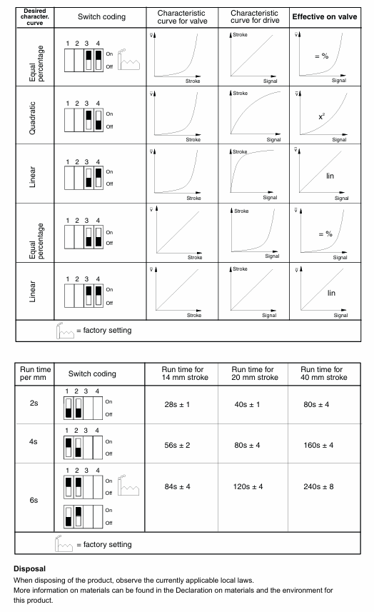
Continuous drive: Connect 0... 10 V/4... 20 mA signals, set the running time through S1/S2, set the flow characteristics through S3/S4, automatically initialize (connect the valve stem to the lower limit of the valve before detecting and saving the stroke at the upper limit), feedback signal corresponds to the effective stroke (0... 10 V corresponds to 0... 100% stroke), no need to reinitialize after power failure.
2-point control (OPEN/CLOSE): Connected by 2 wires at 24 V, terminal 1+2a is powered on, terminal 2b is powered on at 24 V, and the valve stem extends. After power-off, it returns to the opposite terminal position, without feature selection. Terminal 3i/3u/44 is not wired.
3-point control (OPEN/STOP/CLOSE): At 24 V, terminals 2a/2b can be moved to any position when powered on, 1+2b can extend the valve stem when powered on, 1+2a can retract when powered on, and the wiring can be changed to change the direction of travel without feature selection. Terminals 3i/3u/44 are not wired.
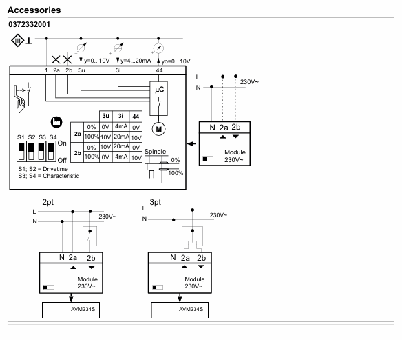
230 V/100... 110 V drive: accessory 0372332 is required. The locator works according to the controller output signal. When both 3u (voltage) and 3i (current) signals are present, high values take priority; There are two operating directions (when the signal increases, the 2a power supply valve stem extends and the 2b power supply valve stem retracts), and a partial range can be set for the boost unit.
Initialization and fault handling
Reinitialize: When powered on and there is a continuous signal from 3u/3i, the crankshaft will be unfolded and retracted twice within 4 seconds, the LED will flash red, and the feedback signal during initialization will be 0. The process will be executed with the shortest running time, and the unfolding of the crankshaft can be interrupted. It will take effect after completion.
Jam handling: Upon detecting a jam, attempt to overcome it within 90 seconds. If unsuccessful, set the feedback signal to 0 V. Once overcome, restore normal control.
Meaning of LED indicator light
|LED Status | Meaning|
|Two lights flashing red | Initialization in progress|
|The red light on the upper light is always on | reaching the upper limit or "off" position|
|The red light under the lamp is always on | reaching the lower limit or "open" position|
|The green light on the upper light is flashing | The actuator is running and moving towards the "off" position|
|The green light on the upper light is always on | The actuator stops, and the last running direction was "off"|
|The green light under the lamp is flashing | The actuator is running and moving towards the "open" position|
|The green light under the lamp is always on | The actuator stops, and the last running direction was "open"|
|No light on | No power supply (terminals 2a/2b have no power)|
|Two lights flashing alternately in red and green | The actuator is in manual mode|
Installation and usage precautions
Installation requirements
Prevent condensation and dripping water from entering the actuator along the valve stem; The valve is directly screwed onto the actuator without additional adjustment, and the actuator stem is in the middle position when it leaves the factory.
Outdoor installation requires additional wind and rain protection; Multiple actuators of the same type can be connected in parallel, and the cross-sectional area of the power cord needs to be selected according to the length and quantity of the cable (such as 5 parallel actuators, 50 m cable, recommended 1.5 mm ²).
The actuator can accommodate up to one 230 V module, one auxiliary accessory (auxiliary contact/potentiometer), and one voltage divider unit.
Temperature related requirements
When the temperature of the valve medium is ≤ 110 ° C, the maximum ambient temperature is 60 ° C; when the temperature of the medium is>110 ° C, the maximum ambient temperature is 55 ° C, otherwise a high-temperature adapter (0372336180) needs to be installed.
Corresponding high-temperature adapters are required for medium temperatures of 180 ° C and above, and the actuator column and valve stem may become hot with the increase of medium temperature, requiring attention to protection.
Compliance and Security
Only for the manufacturer's designated use, modification is prohibited, and relevant product specifications must be followed; If the control unit malfunctions and may cause damage, additional protective measures need to be taken.
Attention should be paid to the rated parameters when using auxiliary contacts. For example, if the gold-plated contact 0372333002 is used once below 10 mA or above 50 V, the gold plating will fail and can only be used in higher rated scenarios.
Disposal
Compliance with current local laws and regulations is required, and material related information can be found in the product's "Material and Environmental Statement".
Size specifications
Actuator size (unit: mm)
|Model | a | b | c|
| AVM 234S F132 | 64 | 289 | 44 |
| AVM 234S F132-5 | 58 | 289 | 38 |
| AVM 234S F132-6 | 78 | 382 | 60 |
High temperature adapter size (unit: mm)
- OMRON
- ABB
- General Electric
- EMERSON
- Honeywell
- HIMA
- ALSTOM
- Rolls-Royce
- MOTOROLA
- Rockwell
- Siemens
- Woodward
- YOKOGAWA
- FOXBORO
- KOLLMORGEN
- MOOG
- KB
- YAMAHA
- BENDER
- TEKTRONIX
- Westinghouse
- AMAT
- AB
- XYCOM
- Yaskawa
- B&R
- Schneider
- KONGSBERG
- NI
- WATLOW
- ProSoft
- SEW
- ADVANCED
- Reliance
- TRICONEX
- METSO
- MAN
- Advantest
- STUDER
- DANAHER MOTION
- Bently
- Galil
- EATON
- MOLEX
- DEIF
- B&W
- ZYGO
- Aerotech
- DANFOSS
- Beijer
- Moxa
- Rexroth
- Johnson
- WAGO
- TOSHIBA
- BMCM
- SMC
- HITACHI
- HIRSCHMANN
- Application field
- XP POWER
- CTI
- TRICON
- STOBER
- Thinklogical
- Horner Automation
- Meggitt
- Fanuc
- Baldor
- SHINKAWA
- Other Brands
- UniOP
- KUKA
- Iba
- Beckhoff
- ADLINK
-
 ETEL DSCDL332-131C-000A Servo Control Board
 -
 ETEL DSCDP324-322F-000C Dual Motor Driver
 -
 ETEL EA-P2M-400-10/20A Position Controller
 -
 ETEL DSC2P121 and DSO-HIO33 Servo Amplifier Set
 -
 ETEL EA-P2M-400-15/40A AccurET Drive
 -
 ETEL EA-P2M-300-07/15A Position Controller
 -
 ETEL EA-P2M-048-05/10A-0100-01 Servo Drive
 -
 ETEL EA-S0M-300-40/80A Servo Drive Guide
 -
 ETEL DSB2P131-111E-000H Digital Servo Amplifier
 -
 ETEL DSCDP334-421-000 Servo Drive Guide
 -
ETEL EA-S0M-300-40 80A-0000-00 Motion Control Module
-
 ETEL UltimET Light Motion Controller EU-LGP-0-0-1000-01 Multi-Axis
 -
 ETEL DSO-RAC601-029 Controller Rack
 -
ETEL DSMAX212-121C-000C Board
-
 ETEL DSCDL132-212B-000C Position Controller
 -
 ETEL TMB0291-050-3TDS-E82 Torque Motor
 -
 ETEL DSMAX212-121-000 Board
 -
 ETEL DSB2P131-111E-000H Digital Servo Controller Amplifier Unit
 -
 ETEL DSB 2S 124-211E-000H Digital Servo Amplifier
 -
 ETEL AccurET EA-P2M-300-4/7.5A-0100-01 Modular Position Controller
 -
 Beckwith Electric M-6280A Digital Capacitor Bank Control
 -
 Beckwith M-2355B Adapter Panel with M-2001C-6SL Tapchanger Control
 -
 Beckwith M-0359 Syncrocloser MOD512
 -
Beckwith Electric M-2001C-6ELFA Tap Changer Controller
-
 Beckwith M-3311A 4-Coil Transformer Protection Relay
 -
 Beckwith M-0124 Terminal Board Adapter Plate Guide
 -
 Beckwith Pride M-0296C 3-Phase Programmable Relay
 -
 Beckwith M-0388 Syncrocloser Check Relay Guide
 -
 Beckwith M-0170A AC Current Relay Guide
 -
Beckwith M-3311 Transformer Protection Relay Guide
-
Beckwith Electric M3310 Integrated Transformer Protection Panel
-
 Beckwith M-0145 First Customer Protector
 -
Beckwith M-0170A AC Current Relay
-
 Beckwith PRIDE M-0296C 3 Phase Programmable Relay
 -
 Beckwith Pride M-0296b 3-Phase Programmable Relay
 -
Beckwith M-0245C High Speed Sync-Check Relay Guide
-
 Beckwith M-0115A AC Parallel Balancing Module
 -
Beckwith M-0389 Voltage Verifier Relay
-
Beckwith M-0115A Parallel Balancing Module
-
 Beckwith M-0389 Voltage Verifier
 -
 Beckwith PRIDE M-0420 Multifunction Relay Protection Module 48VDC
 -
 Beckwith Electric M-3430 Generator Protection Relay
 -
 Beckwith Electric M-0067E Tapchanger Control
 -
 Beckwith Electric M-0420 Multifunction Relay
 -
Beckwith Electric M-2001D-6L4S20C0S0X Tap Changer Control
-
 Beckwith Electric M3425A-STD1 Generator Protection Relay
 -
Beckwith Electric M-0245C High Speed Sync-Check Relay
-
Beckwith Electric M-3520 Intertie Protection Relay Guide
-
Beckwith Electric M-2001C-6SL Tap Changer Control
-
Beckwith Electric M-2001C Tap Changer Control Guide
-
Beckwith 35-12-635 Generator Protection Keypad Interface
-
Beckwith Electric P-2216 Generator Protection Main Board
-
 Beckwith Electric M-2293 Tap Changer Control Guide
 -
 Beckwith M-4272-6AB1EH0 Integrated Synchronizing Motor Bus Transfer
 -
Beckwith Electric M-4272 Motor Bus Transfer 60-140V 50/60Hz
-
Beckwith Electric M-2001B TapChanger Control
-
Beckwith Electric M-0193B Synchrocloser Unit
-
Beckwith Electric M-0115A AC Parallel Balancing Module
-
Beckwith Electric M-0169A Current Transformer
-
 Beckwith Electric P-1939 Generator Protection Annunciator Panel
 -
Beckwith Electric M-3311A Transformer Protection Relay Guide
-
Beckwith Electric M-0245B High Speed Sync-Check Relay
-
Beckwith Electric M3420 Generator Protection Relay
-
 Beckwith M-0193B Syncrocloser Unit
 -
 Beckwith Electric M-520 Intertie Protection Relay
 -
 Beckwith Electric M-3425A Generator Protection Relay
 -
Beckwith M-3425 Integrated Generator Protection Relay
-
Beckwith M-0115A Parallel Balancing Module
-
Beckwith Electric M-4272 Integrated Synchronizing Motor Bus Transfer
-
Beckwith Electric M-3420 Generator Protection System
-
Beckwith M-0193 Syncrocloser Unit
-
 Basler Electric DECS-250-CN1SN1N Digital Excitation Control System
 -
 Basler Electric BE1-700 E0N2X1N Digital Protective Relay
 -
 Basler Electric SR4A-2B15B3A Static Voltage Regulator 120VAC 50/60Hz
 -
 Basler Electric 9261402111 PCB Control Board 9346000033
 -
 Basler Electric BE28053-002 Transformer BE28053002
 -
 Basler Electric BE3-25A Auto Synchronizer B1D Sync Module
 -
 Basler Electric BE3-GPR Generator Protective Relay
 -
 Basler Electric SCP-250-G-60 VAR Power Factor Controller 9 1100 00 109
 -
 Basler Electric BE3-32-1S1N1 Reverse Power Relay 277V 5A
 -
 Basler Electric ACA1300-60GM Area Scan Camera 106200-17
 -
 Basler Electric UFOV 260 A Protection Module Specs
 -
 Basler Electric BE03303001 Control Module
 -
Basler Electric BE3-GPR-P1BVSF Generator Protective Relay
-
 Basler Electric BE1-87G Solid State Protective Relay Guide
 -
 BASLER ELECTRIC BE1-60 VOLTAGE BALANCE RELAY T176884
 -
 Basler Electric BE1-32R Protective Relay
 -
 Basler Electric 9022900-103 Transformer 6-7VA 60Hz
 -
 Basler Electric BE1-59-A4E-E1K-B1S3F Overvoltage Relay
 -
 Basler Electric KR2FF-M Voltage Regulator 9 1163 00 103
 -
 Basler Electric UFOV 260 A Protective Module
 -
 Basler Electric PCB Assembly 9059701100 919620
 -
 Basler Electric SR8A2B01A3E Static Voltage Regulator
 -
 Basler Electric SSR125-12 Static Voltage Regulator 9185900102
 -
 Basler Electric SSR 63-12 Static Voltage Regulator 600VAC
 -
 Basler Electric BE1-60 Solid State Protective Relay
 -
 Basler Electric BE3-47N/27-3A4N2 Voltage Relay 9320400101
 -
 Basler Electric BE1-59 Over Voltage Relay
 -
 Basler Electric DECS100-B15 Automatic Voltage Regulator
 -
 Basler Electric PRS250 Veri-Sync Relay 9088800102
 -
Basler Electric BE25927001 Current Transformer 1:34 Amp
-
Basler Electric 9170818100 Generator Differential Relay
-
 Basler Electric BE1-59N Solid State Ground Fault Overvoltage Relay
 -
 Basler Electric 1783 DC Current Transformer Coil 1200:5A
 -
Basler Electric BE1-67 Ground Directional Overcurrent Relay
-
 Basler Electric UFOV-260A Underfrequency Overvoltage Module
 -
 Basler Electric BE10493001 Control Module
 -
Basler Electric SSR125-12 Static Voltage Regulator Guide
-
 Basler Electric BE1810/U-2 Solid State Frequency Relay Guide
 -
 Basler Electric 9105100106 UFOV-250A Protector Guide
 -
 Basler Electric MOC2199 9072300-335 Relay Module Guide
 -
 Basler Electric 9289902106 Circuit Board
 -
Basler Electric BE1-32R Protective Relay A1E E1P BOS1P
-
 Basler Electric RAL6144-16GM GigE Line Scan Camera with Lens
 -
 Basler Electric BE3-49R-5I5A1 Temperature Relay
 -
 Basler Electric BE1-32R Power Relay B3E E1R A0N1F
 -
 Basler Electric SR4A2B06B3A Static Voltage Regulator Features
 -
 Basler Electric 9121000106 Manual Voltage Control MVC Guide
 -
Basler Electric SR32A-2B15B3E Static Voltage Regulator
-
 Basler Electric SR4A2B06B3A Static Voltage Regulator Guide
 -
Basler Electric 801A193F02 Hammond Transformer Module
-
 Basler Electric BE1-24 Volts Per Hertz Relay A1E F1J D1S0F
 -
 Basler Electric AEC63-7 Analog Excitation Controller 220-277V
 -
Basler Electric BE132R Power Relay T245579
-
 Basler Electric MVC 108 Manual Voltage Control 90 37000 102
 -
 Basler Electric 9022900-103 Control Transformer 6-7VA 60Hz
 -
 Basler Electric BE1-79M Plug Adapter 9170111102
 -
 Basler Electric 9 2007 00 100 Current Boost System CBS 305


