
Yaskawa CP-9200SH Controller
Core advantages:
Modular structure, supporting flexible expansion;
Multi axis control capability, capable of controlling up to 224 axes;
Compatible with multiple communication protocols and I/O modules;
Support hot plugging for easy maintenance;
Equipped with comprehensive debugging and fault diagnosis functions.
Yaskawa CP-9200SH Controller
Core positioning and advantages of the product
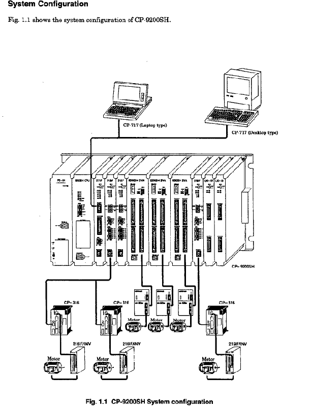
Positioning: Yaskawa CP-9200SH is a high-end industrial controller that integrates sequential control and motion control, designed specifically for industrial machinery that requires high-speed synchronous operation.
Core advantages:
Modular structure, supporting flexible expansion;
Multi axis control capability, capable of controlling up to 224 axes;
Compatible with multiple communication protocols and I/O modules;
Support hot plugging for easy maintenance;
Equipped with comprehensive debugging and fault diagnosis functions.
Detailed explanation of hardware system
1. Core components and module types
(1) Basic module
CPU module: 32-bit processor, optional 1MB/2MB program memory, supports dual CPU configuration, has self diagnosis, program execution control and other functions, and displays the running status through LED indicator lights.
Power module: including PS-01 (100VAC/DC), PS-02 (200VAC), and PS-03 (24VDC) models, with power consumption ≤ 150W, providing power interruption detection function.
Sports module:
SVA module: controls up to 4 axes, supports position/speed/torque control, and also has counter function.
PO-01 module: pulse train output type, capable of controlling up to 4 axes, supporting functions such as positioning and zero point return.
SVB module: MECHATROLINK digital output type, capable of controlling up to 14 axes, with 16 modules expandable to 224 axes.
(2) Optional modules
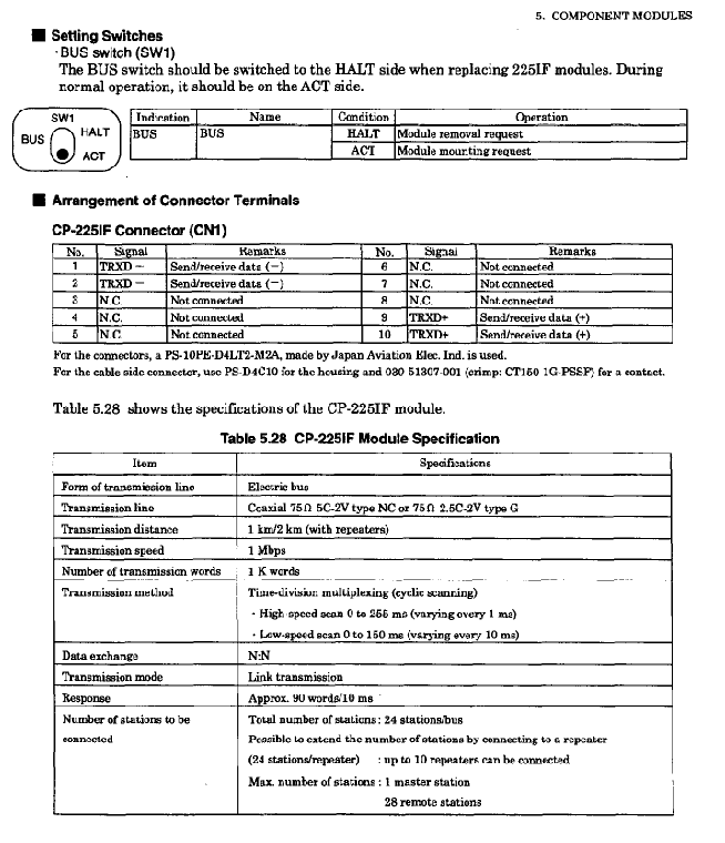
Communication module: Supports CP-213/215/216/217/218/225/2500 protocol and Ethernet, covering interfaces such as RS-232/RS-422/485.
I/O modules: including LIO-01 (32 DI/DO points each), DI-01 (64 point input), DO-01 (64 point output), AI-01 (8-point analog input), AO-01 (4-point analog output), etc.
Expansion modules: EXIOIF (Installation Base Expansion), 2000IOIF (2000 Series I/O Connection), 820IF (CP-820 Local Connection), etc.
(3) Installation base
MB-01 (Long Type): Can install up to 14 modules (excluding power module) and supports single/multiple CPU configurations.
MB-03 (short type): can install up to 8 modules (excluding power module), suitable for scenarios with fewer modules.
2. Key hardware parameters
Environmental parameters: Operating temperature 0-55 ℃ (24-hour average ≤ 50 ℃), vibration resistance meets JIS B 3502 standard.
Grounding requirement: protective grounding (Class 3, ≤ 100 Ω).
Weight: MB-01 with full configuration 5400g, MB-03 with full configuration 3400g.
Module lifespan: At an average ambient temperature of 40 ℃, the module lifespan is 10 years.
3. CP-215 repeater
Used to extend the transmission distance of CP-215/216, supporting twisted pair, coaxial cable, fiber optic and other media, including TT (twisted pair to coaxial), TC (twisted pair to coaxial), TP (twisted pair to plastic fiber), TS2/TS5 (twisted pair to quartz fiber) and other models, with a maximum transmission distance of up to 5km.
Software and programming functions
1. Programming Fundamentals
Programming language: Supports ladder diagrams and SFC language.
Programming tool: Control Pack CP-717 (desktop/laptop), supports program editing, downloading, and debugging.
Program structure: Adopting a hierarchical structure of parent, child, and grandson layers, supporting up to 64 drawings.
2. Core functions
(1) Control function
Motion control: position/speed/torque control, electronic cam, electronic shaft synchronization, positioning, zero return, interpolation feed, etc.
Counting function: reversible counting, interval counting, frequency measurement, hardware position locking.
(2) Communication function
Supports CP-213/215/216/217/218/225/2500 protocol, with Ethernet transmission speed of 10Mbps.
Support third-party communication protocols such as MEMOBU, MELSEC, OMRON, etc., and adapt to different brands of devices.
(3) Debugging and monitoring
Data tracking: Up to 4 sets of 16 data, 32k words of memory, supporting display of lists or trend charts.
Fault tracking: up to 500 fault definitions, recording the time of fault occurrence/recovery and related information.
3. Register and Data Types
Register types: including system registers (S), data registers (M), input registers (I), output registers (O), constant registers (C), etc.
Data types: Supports bit type (B), integer type (W), double length integer (L), real type (F), and address type (A) to meet different computational requirements.
Installation and wiring specifications
1. Installation requirements
Installation location: Avoid direct sunlight, high temperature and humidity, dust, corrosive gases, and vibration impact environments.
Module installation: The power module is located on the left, and the CPU module is located in slot 0/1. The module fastening screws need to be tightened to prevent loosening.
Distance requirement: Maintain sufficient distance from high-voltage equipment, with a distance of ≥ 200mm between I/O lines and power lines to avoid noise interference.
2. Wiring specifications
(1) Power wiring
The power module needs to be connected to the rated voltage, and PS-01/02/03 correspond to different voltage ranges. The wiring should be independent to avoid mixing with other circuits.
Grounding treatment: The FG terminal needs to be grounded separately to avoid sharing with high current grounding, and the grounding resistance should be ≤ 100 Ω.
(2) I/O and transmission wiring
I/O wiring: Use shielded wires to avoid laying them in the same conduit as power lines, and separate the wiring of analog and digital signals.
Transmission wiring: Different communication protocols correspond to different cable types (such as CP-215 using twisted pair), and matching resistors need to be installed at the terminals. The transmission distance must comply with specifications (such as a maximum of 170m at 4Mbps).
3. Hot plugging process
Support live replacement of some modules. The process is: set the BUS switch to HALT → confirm that the RMV LED is on → remove the module → install the new module in HALT mode → tighten the screws → switch the BUS switch to ACT → confirm that the RUN LED is on.

Operation and running process
1. Operation mode
Online operation mode: Execute user programs and I/O operations, RDY and RUN LEDs light up, ALM and ERR LEDs turn off when there are no faults.
Offline stop mode: Program stops, output reset, RUN or RDY LED off, trigger scenarios include no scan time set, program memory not initialized, serious faults, etc.
2. Start the process
Module installation and battery connection (CPU battery needs to be connected separately).
CPU memory initialization (set through DIP switch).
Connect the CP-717 programming tool.
Load the user program.
Start running and perform self diagnosis (including memory, ROM, CPU function diagnosis).
3. Power interruption handling
Instantaneous interruption (≤ 10ms): The device continues to operate.
Short term interruption (10ms Ns): After resetting in continuous startup mode, it continues to run. In new startup mode, it performs self diagnosis and restarts.
Long term interrupt (≥ Ns): After resetting, start according to the set mode.
Fault diagnosis and maintenance
1. Fault diagnosis method
LED indicator light: Determine the fault type based on the on/off/flashing status of RDY, RUN, ALM, ERR, BAT ALM and other LEDs (such as ERR flashing twice as RAM error).
System registers: Query fault details through registers such as SW00040 (CPU status), SW00041 (error message), SW00200 (I/O error count), etc.
Fault classification: serious fault (program stopped), alarm (program continues, ALM LED on).
2. Common fault handling
Power supply error: Check the voltage range, wiring, and terminal screws.
Communication error: Check wiring, terminal resistance, and protocol settings.
Program error: Use CP-717 to troubleshoot program logic and register addresses.
Battery alarm: When BAT ALM lights up, replace the lithium battery (ER6VC) and backup data before replacement.
3. Key points of daily maintenance
Regular inspection: tighten screws, clean modules, and check wiring integrity.
Battery maintenance: Replace the battery in a timely manner before its lifespan expires to avoid data loss.
Module replacement: Non hot swappable modules need to be powered off for replacement, and configuration consistency needs to be confirmed after replacement.
User Program Design
1. Drawing (DWG) type
Including DWG. A (startup drawing), DWG. I (interrupt handling drawing), DWG. H (high-speed scanning drawing), DWG. L (low-speed scanning drawing), supporting hierarchical calling.
Up to 64 drawings, with a maximum of 500 steps per drawing, supporting sub drawing and sub drawing extensions.
2. Function design
System standard functions: 11 preset functions (such as TRACE data tracking, FTRC-RD fault reading).
User defined functions: up to 500, supporting input/output parameter definitions, and can be called across drawings.
3. Symbol and Register Management
Supports direct register number specification or symbol specification (up to 8 characters), with symbols that can be linked upwards (parent symbol referenced by child image).
Automatic register allocation: Some registers support automatic numbering, simplifying the programming process.
- OMRON
- ABB
- General Electric
- EMERSON
- Honeywell
- HIMA
- ALSTOM
- Rolls-Royce
- MOTOROLA
- Rockwell
- Siemens
- Woodward
- YOKOGAWA
- FOXBORO
- KOLLMORGEN
- MOOG
- KB
- YAMAHA
- BENDER
- TEKTRONIX
- Westinghouse
- AMAT
- AB
- XYCOM
- Yaskawa
- B&R
- Schneider
- KONGSBERG
- NI
- WATLOW
- ProSoft
- SEW
- ADVANCED
- Reliance
- TRICONEX
- METSO
- MAN
- Advantest
- STUDER
- DANAHER MOTION
- Bently
- Galil
- EATON
- MOLEX
- DEIF
- B&W
- ZYGO
- Aerotech
- DANFOSS
- Beijer
- Moxa
- Rexroth
- Johnson
- WAGO
- TOSHIBA
- BMCM
- SMC
- HITACHI
- HIRSCHMANN
- Application field
- XP POWER
- CTI
- TRICON
- STOBER
- Thinklogical
- Horner Automation
- Meggitt
- Fanuc
- Baldor
- SHINKAWA
- Other Brands
- UniOP
- KUKA
- Iba
- Beckhoff
-
 Basler DECS-200-2L Digital Excitation Control
 -
 Basler BE1-47N Voltage Phase Sequence Relay
 -
 Basler AEC63-7 Analog Excitation Controller 220-277V
 -
 Basler BE1-50/51B-107 Overcurrent Relay
 -
 Basler Electric BE1‑32R BE1‑E1P‑BON0F Protective Relay
 -
 Basler BE1-25 Solid State Time Overcurrent Relay M1EA6PA5S1F
 -
 Basler MVC 232 Manual Voltage Control Module 90 37000 103 60VAC 55VDC
 -
 Basler RAL6144-16GM Racer GigE Line Scan Camera
 -
 Basler SSR 63-12 Static Voltage Regulator
 -
 Basler BE1-51A Overcurrent Relay
 -
 Basler BE1-87T Solid State Protective Relay
 -
 Basler SR4A2B01B3A Static Voltage Regulator
 -
 Basler SSR 32-12 Static Voltage Regulator
 -
 Basler TRR00696 Transformer 1KVA 115V
 -
 Basler DECS-100-B15 AVR Replacement
 -
Basler BE1-27 Under-Voltage Relay
-
 Basler ACA2000-50GM Interface Module
 -
 Basler AEC63-7 Analog Excitation Controller
 -
 Basler PRS 250 Veri-Sync Relay
 -
 Basler SR4A-2B15B3A Static Voltage Regulator
 -
Basler BE1-32R Power Relay
-
Basler SR8A-2B06B3E Static Voltage Regulator
-
Basler BE1-81 O/U Frequency Relay
-
 Basler BE1-51A-K2E-W6M-B1N0F Overcurrent Relay
 -
Basler BE1-851 Overcurrent Relay G3A1S1 – 48-125V AC/DC
-
 Basler BEI-51 Overcurrent Relay – NSN 5945-01-293-2363
 -
Basler Electric L301KC Protective Relay – L301KC
-
 Basler DECS-100-B15 Automatic Voltage Regulator – Generator AVR
 -
 Basler SR4A-2B15B3A Static Voltage Regulator – SR4A2B15B3A
 -
 Basler UF 312 Under Frequency Protective Module – 9094700100
 -
Basler Electric MVC 232 Manual Control Module – 60VAC 55VDC 20A
-
Basler PRS 250 Veri-Sync Relay – Generator Synchronizing Relay
-
 Basler DECS-100-A05 Digital Regulator Review
 -
 Basler AEM-2020 Analog Expansion Module Specs
 -
 Basler DECS-100-B15 Digital Excitation Specs
 -
Basler Electric 9125600106 Regulator Component
-
Basler BE1-51A-K1E-W6M-B1N0F Overcurrent Relay
-
 Basler MVC-301 MVC 300 Excitation Controller
 -
 Basler SSR 32-12 Static Voltage Regulator
 -
 Basler 9-2849-00-101 Control Module
 -
Basler BE1-51A Overcurrent Relay
-
 Basler BE1-51/27R Overcurrent Relay
 -
 Basler BE1-51 Overcurrent Relay
 -
 Basler SR8A-2B15B3A Static Voltage Regulator
 -
 Basler BE32965001 Transformer and Timer Board
 -
 Basler 9174700100 EL200-7 Excitation Limiter
 -
 Basler BE2000E AVR Voltage Regulator
 -
Basler BE1-87G Differential Relay
-
 Basler BE21834001 Generator Control Module
 -
Basler DECS-100-B15 AVR
-
 Basler D90 96801 100 PCB Card
 -
 Basler XR2002F Voltage Regulator (110 VAC, 48-480 Hz)
 -
 Basler SR8A-2B14B3A Regulator
 -
 Basler 9561500100 Module
 -
 Basler DECS-400 BE1-11 System
 -
 Basler DECS-100-B15 Excitation Control
 -
 Basler SCP 210 Frequency Controller
 -
Basler SR4A-2B15B3A Static Voltage Regulator
-
Basler BE1-32R Power Relay
-
 Basler PIA2400-17GM Power Interface Adapter
 -
 Basler MVC 232 Manual Voltage Control Module
 -
 Basler SSR 32-12 Static Voltage Regulator
 -
Basler 5MW AVR Generator Voltage Regulator
-
 Basler VR63-4B Voltage Regulator
 -
Basler DECS-100-A05 AVR for Engine Generator
-
Basler DECS-100-B15 Automatic Voltage Regulator
-
Basler BE1-32R Directional Power Relay
-
Basler BE1-87B Differential Relay
-
 Basler UFOV 260A Protective Module
 -
 Basler 9-2614-02-100 PCB Rev M
 -
Basler DECS-100-B15 Digital AVR
-
 Basler 9284900103 PS DECS-400N
 -
 Basler D4N3H1U Intertie Protection
 -
 Basler DECS-100-B15 A15 AVR
 -
 Basler KR4F Voltage Regulator
 -
 Basler BE26434 T14 Transformer
 -
 Basler SR8A-2B15B3A Regulator
 -
 Westinghouse 774B472A12 AR Relay
 -
Basler DECS-100-B15 AVR
-
Basler XR2002F Regulator 110V
-
Basler SR125-E Static Regulator
-
Basler SSR 125-12 Regulator
-
Basler MOC2599 Motor Pot
-
 Basler BE1-DFPR Feeder Relay
 -
 Basler CBS 305 Current Boost
 -
Basler BE1-25 AutoSync
-
Basler MVC 300 Voltage Control
-
 Basler BE3-25A AutoSync
 -
 Basler KR7FF Static Regulator
 -
Basler 90-49000-100 Regulator
-
 Basler 880 kVA Dry Type Transformer Specs
 -
Basler Electric BE1-25 Sync-Check Relay Specs
-
 Basler SSR 125-12 Voltage Regulator Specs
 -
 Basler Electric BE1-851 Overcurrent Relay Review
 -
Basler Electric 149D930G02 Control Sub-Assembly
-
 Basler Electric BE1-81O/UT Frequency Relay Specs
 -
 Basler Electric BE1-51/27C Overcurrent Relay
 -
 Basler Electric 149D956G02 Industrial Component
 -
Basler Electric BE1-51A Overcurrent Relay Specs
-
 Basler Electric BE1-40Q Loss of Excitation Relay
 -
Basler DECS-200 Excitation Control System
-
 Basler DECS-200 Voltage Regulator 56-277V AC / 125V DC
 -
Basler BE1-87T Transformer Differential Relay
-
 Basler RDP-110-S1 Protection Relay
 -
 Basler BE1-700V Digital Protective Relay
 -
 Basler BE1-951 Overcurrent Protection System
 -
 Basler DECS-300 Digital Excitation Control
 -
 Basler DECS-200 Digital Excitation Control
 -
 Basler DECS-200-1C Excitation Control System
 -
Basler DECS-200-1L Digital Excitation Control
-
 Basler Electric BE1-GPS Generator Protection System
 -
Basler Electric DECS-200-1C Digital Excitation Controller
-
 Basler Electric DECS125-15 Excitation Control with Power Module
 -
Basler Electric BE1-87G Differential Relay
-
 Basler Electric BE1-11 Protection System I5A3M2P2N0EA00
 -
Basler Electric DECS-200-1C Excitation Control System
-
Basler Electric BE1-11g Generator Protection Relay
-
Basler Electric DECS 125-15-B2C1 V2.0.9 Excitation Control
-
Basler Electric BE1-81O/UT3ED1JA7N2F Frequency Relay
-
Basler Electric BE1-81O/UT3EE1YB7N1F Frequency Relay
-
 Basler Electric DECS-200-1L Digital Excitation Control System
 -
Basler DECS125-15-B2C1 Excitation Control
-
 Basler 9507900205 SSR Retrofit Voltage Regulator
 -
 Basler BE2000E Digital Voltage Regulator
 -
 Basler BE1-GPS Generator Protection System
 -
Basler DECS-250-CN1CN1N Digital Excitation Control
-
 Basler DGC-2020 Genset Controller
 -
Basler BE1-81O UT3ED1LA7N0F Frequency Relay (Variant)


