
Honeywell CR-6A Six Relay Control Module Installation and Maintenance
Disconnect the power supply of the control panel before installing the module.
This system contains static sensitive components. Before handling any circuit, it is necessary to ground it with a suitable wrist strap to eliminate static charges on the body.
Honeywell CR-6A Six Relay Control Module Installation and Maintenance
Product specifications
Normal operating voltage: 15-32 VDC
Standby current: 1.45 mA
Alarm current: 32 mA (assuming all six relays have switched once and all six LEDs are continuously on)
Temperature range:
ULC application: 32 ° F to 120 ° F (0 ° C to 49 ° C)
EN54 application: -10 ° C to 55 ° C
Humidity:
ULC application: 10% to 95%, non condensing
EN54 application: 10% to 93%, non condensing
Size: 6.8 inches high x 5.8 inches wide x 1.0 inches deep (173mm high x 147mm wide x 25mm deep)
Maximum IDC wiring resistance: 40 ohms
Accessories: BB-2A cabinet, BB-6A cabinet, CH-6A chassis, or appropriately grounded metal cabinet
Wire gauge: 12-18 AWG (0.9mm ² -3.25mm ²)
Relay current: 30 mA/relay pulse (15.6ms pulse duration, under panel control)
Preparation before installation
This information is only provided as a quick reference installation guide. If modules are installed in the existing operating system, operators and local authorities should be notified that the system will be temporarily suspended.
Disconnect the power supply of the control panel before installing the module.
This system contains static sensitive components. Before handling any circuit, it is necessary to ground it with a suitable wrist strap to eliminate static charges on the body.
The enclosure cabinet should be made of metal material and properly grounded.
This manual should be left to the owner/user of this device.
Product overview
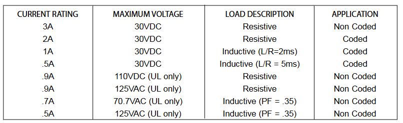
Purpose: Suitable for intelligent alarm systems, used for Form-C switching applications, load circuits do not require wiring monitoring.
Structure: Each module provides a set of independent dry-type relay contacts, which can be wired as normally open or normally closed; Each module has its own address, and the address of the first module is set to 01 to 94 through a pair of rotary encoding switches. The remaining modules are automatically assigned to the next five higher addresses; Disable up to three unused modules to release addresses for use elsewhere; Each CR-6A module also has a green LED indicator light controlled by the panel, which can make the LED flash, lock on or lock off.
Includes: 6 1 × 3 terminal blocks, 1 1 × 4 terminal block, 2 1.25-inch (32mm) supports, 3 mechanical screws, 1 splitter (note: in the disabled position, a maximum of one splitter can be installed at the same time)
Compatibility requirements
To ensure normal operation, this module should only be connected to compatible control panels.
Component
Installation options:
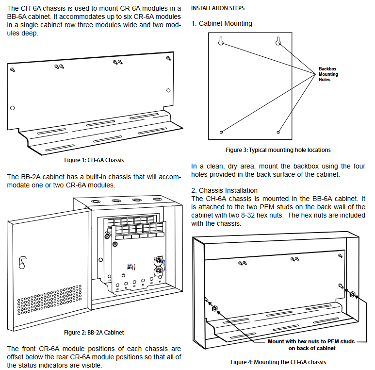
Up to six CR-6A modules can be installed on the CH-6A of the BB-6A cabinet
One or two CR-6A modules can be installed in the BB-2A cabinet
Chassis: CH-6A chassis is used to install CR-6A modules in the BB-6A cabinet. It can accommodate up to six CR-6A modules in a single cabinet row, three modules wide and two modules deep; The BB-2A cabinet has a built-in chassis that can accommodate one or two CR-6A modules. The front CR-6A module position of each chassis is lower than the rear CR-6A module position, so that all status indicators are visible.
Cabinet: BB-6A cabinet can accommodate CH-6A chassis with up to six CR-6A modules installed; The BB-2A cabinet accommodates one or two CR-6A modules on its internal chassis, and the cabinet dimensions refer to the cabinet installation document.
Installation steps
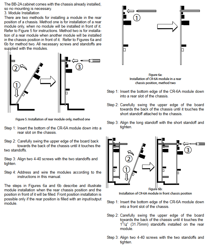
Cabinet installation: Install the bottom box using the four holes provided on the back of the cabinet in a clean and dry area.
Chassis installation: The CH-6A chassis is installed in the BB-6A cabinet and secured to the two PEM bolts on the rear wall of the cabinet with two 8-32 hex nuts, which are provided with the chassis; The BB-2A cabinet comes with an installed chassis and does not require additional installation.
Module installation: There are two methods to install modules at the rear of the chassis.
Method 1: Install only the rear module and do not install any modules in front of it.
Method 2: Install the rear module, and another module will be installed in front of it. All necessary screws and supports are provided with the module.
Wiring requirements
All wiring must comply with applicable local codes, regulations, and laws.
Install module wiring according to the engineering drawings and corresponding wiring diagrams.
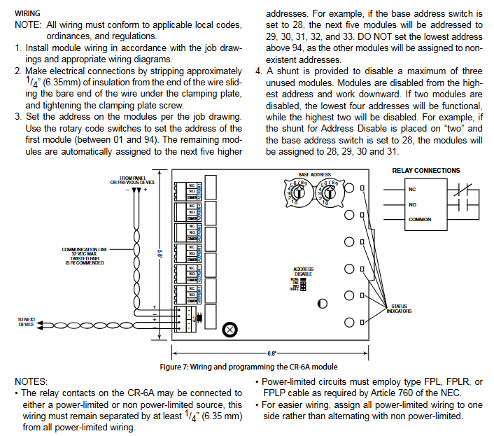
When making electrical connections, strip approximately 0.25 inches (6.35mm) of insulation from the end of the wire, slide the exposed end of the wire under the clamp, and then tighten the clamp screws.
Set the address on the module according to the engineering drawing, use the rotary encoding switch to set the address of the first module (between 01 and 94), and the remaining modules will be automatically assigned to the next five higher addresses. For example, if the base address switch is set to 28, the next five modules will be addressed as 29, 30, 31, 32, and 33. The minimum address cannot be set to 94 or above, otherwise other modules will be assigned to non-existent addresses.
Provide a splitter to disable up to three unused modules. The module is disabled starting from the highest address and moving downwards. For example, if the shunt with "address disabled" is placed on "2" and the base address switch is set to 28, the module will be assigned to 28, 29, 30, and 31.
Precautions for Relay Connection
The relay contacts on CR-6A can be connected to power limited or non power limited power sources, but the wiring must be kept at least 0.25 inches (6.35mm) away from all power limited wiring.
The power limiting circuit must use FPL, FPLR, or FPLP type cables as required by NEC Article 760.
For ease of wiring, allocate all power limiting wiring to one side instead of alternating with non power limiting wiring.
- OMRON
- ABB
- General Electric
- EMERSON
- Honeywell
- HIMA
- ALSTOM
- Rolls-Royce
- MOTOROLA
- Rockwell
- Siemens
- Woodward
- YOKOGAWA
- FOXBORO
- KOLLMORGEN
- MOOG
- KB
- YAMAHA
- BENDER
- TEKTRONIX
- Westinghouse
- AMAT
- AB
- XYCOM
- Yaskawa
- B&R
- Schneider
- KONGSBERG
- NI
- WATLOW
- ProSoft
- SEW
- ADVANCED
- Reliance
- TRICONEX
- METSO
- MAN
- Advantest
- STUDER
- DANAHER MOTION
- Bently
- Galil
- EATON
- MOLEX
- DEIF
- B&W
- ZYGO
- Aerotech
- DANFOSS
- Beijer
- Moxa
- Rexroth
- Johnson
- WAGO
- TOSHIBA
- BMCM
- SMC
- HITACHI
- HIRSCHMANN
- Application field
- XP POWER
- CTI
- TRICON
- STOBER
- Thinklogical
- Horner Automation
- Meggitt
- Fanuc
- Baldor
- SHINKAWA
- Other Brands
- UniOP
- KUKA
- Iba
- Beckhoff
- ADLINK
-
 SIGMATEK CTS051 12-053-051 Control Module
 -
 SIGMATEK CTS022 Control Module
 -
 Sigmatek 01-250-010-D NC4Kompakt V2.1 Module
 -
 SIGMATEK Control Keyboard 01-285-042 Interface
 -
 SIGMATEK TO081 20-007-081 Digital Output Module
 -
 Sigmatek AKM73Q-ANCNGBB0 7.07kW Servo Motor
 -
 Sigmatek DIP012 Demag 07024165 Processor Module
 -
 SIGMATEK PC 411 Injection Molding Controller
 -
 SIGMATEK CEZ201 12-051-201-O Processor Module
 -
 SIGMATEK VI021 20-003-021 Digital Input Module
 -
 SIGMATEK Computer C-IPC 144904 Industrial PC
 -
 SIGMATEK 9307.083.01 9305.081.02 Industrial Module
 -
 SIGMATEK AI075 Analog Input Module
 -
 SIGMATEK HGT834-W Teaching Pendant
 -
Sigmatek CDI161 Digital Input Module
-
 SIGMATEK HGT834 Teaching Pendant
 -
 SIGMATEK CEZ201 12-051-201-O Module
 -
SIGMATEK Demag 9617.067.03 9708.244.00 Module
-
 SIGMATEK SCP010 Safety CPU Module
 -
SIGMATEK N100 20-011-100 Module
-
 SIGMATEK CNC 031 Positioning Output Module
 -
 Sigmatek 01-355-016 Control Module
 -
 Sigmatek MDM021 Digital Mixed Module
 -
Sigmatek DAI411 05-020-411 Analog Module
-
Attitude Gyro 1U367-232-2 Aircraft Instrument
-
 Sigma-Tek 5000B-36 Attitude Gyro 23-501-06-16
 -
Sigmatek HGT834-W Injection Molding Teach Pendant
-
Sigma Tek 5000EG Attitude Gyro 1U670-003-12
-
 Sigmatek HGT834-W Teach Pendant
 -
 Sigmatek DEE011 05-068-011 Module
 -
 Sigmatek DIAS DCP643 Central Processing Unit
 -
 Sigmatek MDD111-1 DIAS Drive Axis Module
 -
 Sigmatek DKL042 05-024-042 Terminal Module
 -
Sigmatek DM822 Control Module
-
Sigmatek CDM167 12-008-167-O Module
-
Sigmatek TAE151 Touch Display Unit
-
 Sigmatek DCC041 SLIDES Module 05-700-041-D
 -
Sigmatek AKM65M-ANC2GBB0 PM Servo Motor
-
 Sigmatek ETT221 01-230-221 Operator Terminal
 -
Sigmatek SLIDES DAM 124 Analog Module
-
Sigmatek AKM31C-ANCNGBB0 Servo Motor
-
 Mannesmann Demag Sigmatek CP626 Central Unit
 -
 SIGMATEK 0332.554.03 Board 371071000154
 -
 SIGMATEK 12-250-021 Base Plate Back Panel CM5V020
 -
 SIGMATEK DM162 S-DIAS Digital Mix Module
 -
 DEMAG ERGOTECH 061 381 66 Sigmatek 9842.243.02 Circuit Board
 -
 SIGMATEK CP313-1 PLC Module
 -
Sigmatek ETV0551-2 VARAN Touch Terminal
-
 Sigmatek SDM 081 FS S-Dias Safety Module
 -
 DEMAG 05-250-023 Ergotech Motherboard with Sigmatek TMS012
 -
Sigmatek CM5V020 12-250-023-K Wiring Base
-
Sigma Tek 5000B-37 Attitude Gyro Indicator
-
Sigmatek SDD120-2 DIAS Drive
-
 Sigmatek CME221 Memory Module
 -
 Sigmatek DCP640 DIAS Central Unit
 -
 Sigmatek STO040 Safety Output Module
 -
Sigmatek CET281 Control Panel
-
 Sigmatek CIPC LX800 Demag NC5 CPU
 -
Sigmatek DKL093 05-024-093 Terminal Module
-
 Sigmatek AI088 20-009-088 Analog Input Module
 -
Sigmatek CAI888 Analog Input Module
-
SIGMATEK CCA021 12-025-021 Analog Output Module
-
SIGMATEK 1104.579.05 Control Module
-
SIGMATEK SDI100 Digital Input Module
-
 SIGMATEK C-IPC 256MB LX800 Compact Dias
 -
SIGMATEK 9423.090.02 Control Module
-
SIGMATEK C-IPC 256 Power Supply 148498
-
SIGMATEK CAI025 Analog Input Module
-
 SIGMATEK CTO166 Digital Output Module
 -
 SIGMATEK CP112 20-004-112 Processor Module
 -
SIGMATEK CAI887 12-009-887 Safety Module
-
 Sigma-Tek 4000B-31 Directional Gyro 1U262-002-42
 -
Sigmatek C-IPC 256MB LX800 IPC Controller
-
Sigmatek C-IPC 01-450-031 Industrial PC LX800
-
Sigmatek C-IPC 256 Industrial PC Controller
-
Sigmatek CCP-531 PLC Processor Module
-
Sigmatek CDI163 Digital Input Module
-
 Sigmatek ETV0501 VARAN Terminal 12-230-0501
 -
 Sigmatek CTMS020 C-DIAS Technology Module
 -
 Sigmatek CIV512 VARAN Switch Module
 -
Sigmatek HU011 20-080-011 Interface Module
-
SIGMATEK SLIDES DAM 124 Module
-
 SIGMATEK C-IPC 161 01-450-161L Industrial PC
 -
SIGMATEK C-IPC 128MB VIA 733MHz 01-450-024-K
-
 SIGMATEK 12-780-012 R8-IPC Geode LX800 Module
 -
SIGMATEK CAM124 Analog Module
-
 SIGMATEK S1 032-8AF61-R4 EZ Servo Motor
 -
 SIGMATEK CTO163 Digital Output Module
 -
SIGMATEK CCP082 12-004-082 Processor Module
-
 SIGMATEK CRCH081 C-DIAS Temperature Module
 -
SIGMATEK PC322-K 01-310-322-K Industrial PC
-
SIGMATEK SDD310-2 Servo Drive
-
 SIGMATEK AI084 Analog Input Module
 -
SIGMATEK CRCH081 12-752-081 Temperature Module
-
Sigma-Tek 5000L-4 Attitude Gyro 1U284-001-3
-
 SIGMATEK CM5V020 12-250-023-K Wiring Module
 -
Sigma-Tek 4000H-6 Directional Gyro IU262-035-7
-
SIGMATEK Dias DCP160 05-004-160 Processor Module
-
SIGMATEK 0147.395.02 Control Module
-
SIGMATEK A1084 Control Module
-
SIGMATEK DI200 20-006-2000 Digital Input Module
-
Sigmatek DNC115 Encoder Module
-
 Sigmatek DAM122 05-017-122 Analog Module
 -
Sigmatek 9802.289.01 Control Board TA71 Display
-
Sigmatek TO127 20-007-127 Digital Output Module
-
Sigmatek DNC031 05-011-031 Digital Module
-
Sigmatek VI022 20-003-022 Interface Module
-
Sigmatek CAI085 Analog Input Module
-
 Sigmatek CP111 S-DIAS CPU Module
 -
Sigmatek CTMS030 Krauss Maffei Module
-
 Sigmatek CAM123 Control Module
 -
 Sigmatek TAE732-P 01-240-732-P Touch Display Unit
 -
Sigmatek MDM021 Digital Mixed Module
-
Sigmatek DCP642 DIAS Central Unit
-
 Sigmatek CST022 12-014-022 C-DIAS Module
 -
 Sigmatek SRO021 20-893-021 Safety Relay Output
 -
 Krauss Maffei MC5 Control System Sigmatek
 -
 Sigmatek DC061 Module 18-24VDC 300mA
 -
 Herrmann EVT0855 Ultrasonic Welder Touch Panel
 -
Sigmatek CIV521 Control Module 1.4A 2W
-
Sigmatek DDI61 05-006-161 Digital Input Module
-
SIGMATEK ETT312-E Touch Terminal 01-230-312
-
Cessna S3326-1 Sigma Tek 5000B-67 Gyro 1U149-015-9
-
SIGMATEK PS101 Power Supply Module
-
SIGMATEK 0332.554.03 Control Module 371071000154
-
 SIGMATEK ETT312-E Touch Terminal 01-230-312
 -
SIGMATEK CDM163 Control Module
-
SIGMATEK VSV046 16-023-046 Module


