
Honeywell CR-6A Six Relay Control Module Installation and Maintenance
Disconnect the power supply of the control panel before installing the module.
This system contains static sensitive components. Before handling any circuit, it is necessary to ground it with a suitable wrist strap to eliminate static charges on the body.
Honeywell CR-6A Six Relay Control Module Installation and Maintenance
Product specifications
Normal operating voltage: 15-32 VDC
Standby current: 1.45 mA
Alarm current: 32 mA (assuming all six relays have switched once and all six LEDs are continuously on)
Temperature range:
ULC application: 32 ° F to 120 ° F (0 ° C to 49 ° C)
EN54 application: -10 ° C to 55 ° C
Humidity:
ULC application: 10% to 95%, non condensing
EN54 application: 10% to 93%, non condensing
Size: 6.8 inches high x 5.8 inches wide x 1.0 inches deep (173mm high x 147mm wide x 25mm deep)
Maximum IDC wiring resistance: 40 ohms
Accessories: BB-2A cabinet, BB-6A cabinet, CH-6A chassis, or appropriately grounded metal cabinet
Wire gauge: 12-18 AWG (0.9mm ² -3.25mm ²)
Relay current: 30 mA/relay pulse (15.6ms pulse duration, under panel control)
Preparation before installation
This information is only provided as a quick reference installation guide. If modules are installed in the existing operating system, operators and local authorities should be notified that the system will be temporarily suspended.
Disconnect the power supply of the control panel before installing the module.
This system contains static sensitive components. Before handling any circuit, it is necessary to ground it with a suitable wrist strap to eliminate static charges on the body.
The enclosure cabinet should be made of metal material and properly grounded.
This manual should be left to the owner/user of this device.
Product overview
Purpose: Suitable for intelligent alarm systems, used for Form-C switching applications, load circuits do not require wiring monitoring.
Structure: Each module provides a set of independent dry-type relay contacts, which can be wired as normally open or normally closed; Each module has its own address, and the address of the first module is set to 01 to 94 through a pair of rotary encoding switches. The remaining modules are automatically assigned to the next five higher addresses; Disable up to three unused modules to release addresses for use elsewhere; Each CR-6A module also has a green LED indicator light controlled by the panel, which can make the LED flash, lock on or lock off.
Includes: 6 1 × 3 terminal blocks, 1 1 × 4 terminal block, 2 1.25-inch (32mm) supports, 3 mechanical screws, 1 splitter (note: in the disabled position, a maximum of one splitter can be installed at the same time)
Compatibility requirements
To ensure normal operation, this module should only be connected to compatible control panels.
Component
Installation options:
Up to six CR-6A modules can be installed on the CH-6A of the BB-6A cabinet
One or two CR-6A modules can be installed in the BB-2A cabinet
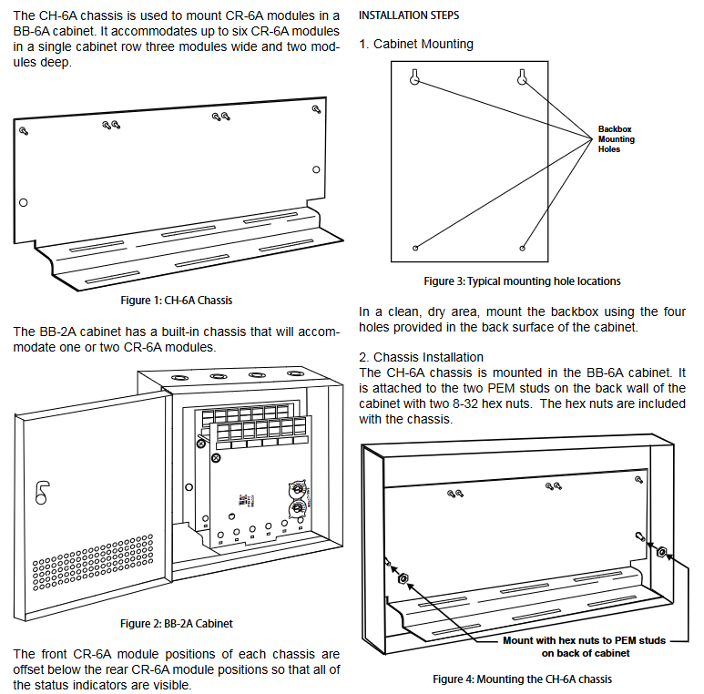
Chassis: CH-6A chassis is used to install CR-6A modules in the BB-6A cabinet. It can accommodate up to six CR-6A modules in a single cabinet row, three modules wide and two modules deep; The BB-2A cabinet has a built-in chassis that can accommodate one or two CR-6A modules. The front CR-6A module position of each chassis is lower than the rear CR-6A module position, so that all status indicators are visible.
Cabinet: BB-6A cabinet can accommodate CH-6A chassis with up to six CR-6A modules installed; The BB-2A cabinet accommodates one or two CR-6A modules on its internal chassis, and the cabinet dimensions refer to the cabinet installation document.
Installation steps
Cabinet installation: Install the bottom box using the four holes provided on the back of the cabinet in a clean and dry area.
Chassis installation: The CH-6A chassis is installed in the BB-6A cabinet and secured to the two PEM bolts on the rear wall of the cabinet with two 8-32 hex nuts, which are provided with the chassis; The BB-2A cabinet comes with an installed chassis and does not require additional installation.
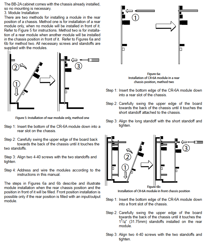
Module installation: There are two methods to install modules at the rear of the chassis.
Method 1: Install only the rear module and do not install any modules in front of it.
Method 2: Install the rear module, and another module will be installed in front of it. All necessary screws and supports are provided with the module.
Wiring requirements
All wiring must comply with applicable local codes, regulations, and laws.
Install module wiring according to the engineering drawings and corresponding wiring diagrams.
When making electrical connections, strip approximately 0.25 inches (6.35mm) of insulation from the end of the wire, slide the exposed end of the wire under the clamp, and then tighten the clamp screws.
Set the address on the module according to the engineering drawing, use the rotary encoding switch to set the address of the first module (between 01 and 94), and the remaining modules will be automatically assigned to the next five higher addresses. For example, if the base address switch is set to 28, the next five modules will be addressed as 29, 30, 31, 32, and 33. The minimum address cannot be set to 94 or above, otherwise other modules will be assigned to non-existent addresses.
Provide a splitter to disable up to three unused modules. The module is disabled starting from the highest address and moving downwards. For example, if the shunt with "address disabled" is placed on "2" and the base address switch is set to 28, the module will be assigned to 28, 29, 30, and 31.
- OMRON
- ABB
- General Electric
- EMERSON
- Honeywell
- HIMA
- ALSTOM
- Rolls-Royce
- MOTOROLA
- Rockwell
- Siemens
- Woodward
- YOKOGAWA
- FOXBORO
- KOLLMORGEN
- MOOG
- KB
- YAMAHA
- BENDER
- TEKTRONIX
- Westinghouse
- AMAT
- AB
- XYCOM
- Yaskawa
- B&R
- Schneider
- KONGSBERG
- NI
- WATLOW
- ProSoft
- SEW
- ADVANCED
- Reliance
- TRICONEX
- METSO
- MAN
- Advantest
- STUDER
- DANAHER MOTION
- Bently
- Galil
- EATON
- MOLEX
- DEIF
- B&W
- ZYGO
- Aerotech
- DANFOSS
- Beijer
- Moxa
- Rexroth
- Johnson
- WAGO
- TOSHIBA
- BMCM
- SMC
- HITACHI
- HIRSCHMANN
- Application field
- XP POWER
- CTI
- TRICON
- STOBER
- Thinklogical
- Horner Automation
- Meggitt
- Fanuc
- Baldor
- SHINKAWA
- Other Brands
- UniOP
- KUKA
- Iba
- Beckhoff
-
 Basler XR2002F Voltage Regulator 9139400101
 -
 Basler 2D80367G23 DXCB De-Excitation Module 1200V 5000A
 -
 Basler SR4A-2B15B3A Static Regulator 120V 50/60Hz
 -
 Basler SSR 125-12NF Static Regulator 9 1859 00 106
 -
 Basler BE1-BPR Breaker Protection Relay 9272000315
 -
 Basler SSR 63-12 Static Regulator 9 1859 00 101
 -
 Basler AEM-2020 Analog Expansion Module
 -
 Basler BE 25231-001 Transformer BE25231001
 -
 Basler MVC 108 Manual Voltage Control 9037000102
 -
 Basler PSS-100-Y5 Power System Stabilizer 0.1-5.0Hz
 -
 Basler Electric BE1A-25-M1G-A6T-N4V1F Sync-Check Relay
 -
 Basler Electric SR8A2B10B1A Static Voltage Regulator
 -
Basler Electric SR8A2B10B1A Static Voltage Regulator
-
Basler Electric SSR 125-12 Static Voltage Regulator 9185900102
-
 Basler Electric 90-73900-102 Power Supply (Westinghouse 2374A07G03)
 -
 Basler Electric 9400200117 Control Power Unit 12/24VDC 20W
 -
Basler Electric BE1-87G Solid State Generator Differential Relay
-
 Basler Electric BE1-32R Style C3ED1TA0S1F Solid State Protective Relay
 -
Basler Electric SR32A2B05B3E Static Voltage Regulator
-
 Basler Electric SR8A2B06B3A Static Voltage Regulator
 -
Basler MOC3502 90-72300-116 Motor Potentiometer
-
 Basler SR4A2310B1A Static Voltage Regulator
 -
 Basler Electric 90-88800-102 PRS-250 Veri-Sync Relay
 -
Basler Electric 90-88800-102 PRS-250 Veri-Sync Relay
-
Basler SR4A-2B05A3E Static Regulator SR4A2B05A3E
-
 Basler 9-0723-00-130 9072300130 Control Module
 -
 Basler BE1-79MA10A6JC0L0F Reclosing Relay
 -
 Basler CBS-377 Current Boost System 91096001
 -
Basler SR4A1B05A3A Static Regulator 480V 62.5V 10VA
-
 Basler BE159N A7ED1JC0S0F Protective Relay BE159N-0
 -
 Basler BE3-25A Auto-Synchronizer S.No. 728
 -
 Basler BE1-50 Instantaneous Overcurrent Relay G4EA1RG0N0F
 -
 Basler Electric KT3B Voltage Regulator
 -
 Basler Electric ACA2500-14GCSYM GigE Camera
 -
 Basler Electric XR2002F Voltage Regulator
 -
 Basler Electric BE1-50 Instantaneous Overcurrent Relay F2EA1PA0N5F
 -
 Basler Electric CBS 212A Current Boost System
 -
Basler Electric BE147NE3FE1PC3N3F Negative Sequence Voltage Relay
-
 Basler Electric BE1-79MA10A6JC0L0F Automatic Reclosing Relay
 -
Basler Electric BE1-59N A6E E1C B0N1F Neutral Overvoltage Relay
-
 Basler Electric MVC 108 Manual Voltage Control
 -
 Basler Electric BE1-59-A4E-E1C-A0N0F Overvoltage Relay
 -
Basler BE1-57/27R Solid State Protective Relay
-
 Basler BE3-25AX Time Overcurrent Relay
 -
BASLER ELECTRIC BE1-24/A1EF1JC1N0F / BE124A1EF1JC1N0F Overvoltage Relay
-
Basler Electric Solid State Protective Relay BE1-32R Style B2ED1PB0N0F
-
Basler BE3-51-3E1E1 9320000110 24VDC Overcurrent Relay
-
 Basler UFOV 260A Underfrequency Overvoltage Module
 -
 Basler 50F4EA1PA0N0F Instantaneous Overcurrent Relay
 -
Basler BE1-50 Instantaneous Overcurrent Relay
-
 Basler BE1-32 Solid State Protective Relay
 -
Basler SCP 250-G-60 VAR Power Factor Controller
-
Basler BE1-59N A5EE1KC0N0F Ground Fault Relay
-
Basler BE1-79A Reclosing Relay
-
Basler BE1-32R E1EA1OA0N0F Reverse Power Relay
-
 Basler DCQA-103 DCQC104-1 CMX-7D Circuit Board
 -
 Basler SSR125-12 Static Regulator 918500102
 -
Basler 90 17709 112 Regulator Control Board
-
 Basler AVC63-4 AVC634 Voltage Regulator
 -
 Basler 9 1049 04 100 PC Board Control Module
 -
Basler SR4A-2B03B3A Static Voltage Regulator
-
 Basler SR8A-2B15B3A Static Voltage Regulator
 -
 Basler KR7FFX Static Regulator 840V
 -
 Basler EL200-7 Voltage Regulator 90-660VAC 7A
 -
 Basler PRP210-1 Reverse Power Relay 9056300102
 -
 Basler SSR 63-12 Static Regulator 600VAC
 -
 Basler 9289901106 Digital Board
 -
Basler DECS100 Voltage Regulator DECS100A01
-
Basler Electric CEM-2020 Contact Expansion Module
-
Basler Electric BE3-25-1 C1 N4 Synchronizing Check Relay
-
Basler Electric ACA2000-50GM GigE Camera 2MP 50fps
-
 Basler Electric ACA2240-20GMSYM GigE Camera Sony IMX264
 -
Basler BE1-50G Ground Overcurrent Relay
-
Basler PRS250 Veri-Sync Relay
-
Basler MOC2199 Output Module
-
 Basler UFOV 260A Underfrequency Overvoltage Module
 -
 Basler BE-15482-001 Control Module
 -
Basler LSP4-7 Protective Relay
-
 Basler SCP 250-G-60 VAR Power Factor Controller
 -
Basler BE146N Negative Sequence Overcurrent Relay
-
Basler APR63-5 Automatic Voltage Regulator
-
Basler 9507900107 SR8A Retrofit Voltage Regulator
-
Basler BE1-320 Directional Power Relay
-
 Basler KR7F Voltage Regulator 9116200100
 -
Basler UFOV 260A Overvoltage Protective Module
-
 Basler AEC63-7 Analog Excitation Controller
 -
Basler 9992D90G01 Control Module
-
Basler 6966D22G01 Control Board
-
Basler 6965D40G01 Control Board
-
 Basler BE1-50/51M-104 Overcurrent Relay
 -
Basler BE1-BPR Programmable Breaker Relay
-
 BASLER Electric SSR 125-9 1256 00 102 Static Voltage Regulator
 -
Basler Electric MVC 112 Manual Voltage Control
-
 Basler Electric 9321000102 Control Module
 -
 Basler Electric RA-70-MDCT7 Rectifier Assembly
 -
 Basler Electric ACA1300-60GM GigE Camera
 -
 Basler Electric 6427C85G01 Interface Board
 -
Basler Electric 6965D05G01 Control Board
-
Basler Electric ACA2500-14UC Current Transducer
-
Basler Electric 9170206111 Protective Relay
-
Basler Electric BE1-11-G6D1M1J1P0E000 Protection Relay
-
Basler Electric BE1-50/51B-107 Overcurrent Relay
-
 Basler 9121000106 Voltage Controller
 -
 Basler B3E-E1P-A0N0F Solid State Protective Relay
 -
 Basler 9121000106 Manual Voltage Control
 -
Basler PRP320 Motor Pull-out Relay
-
 Basler SSE-N 250-9KW Shunt Exciter Regulator
 -
 Basler BE1-50-51B-107 Overcurrent Relay
 -
 BASLER ELECTRIC MVC 108 MANUAL VOLTAGE CONTROL MODULE 9 0370 00 102
 -
Basler BE1-59N-A7E-D1J-D0N0F Ground Overvoltage Relay
-
Basler BE1-46N-G1E-B8P-B0N0F Negative Sequence Overcurrent Relay
-
Basler BE1-951 Overcurrent Protection System
-
 Basler Electric MOC2199 Motor Operated Potentiometer
 -
Basler Electric BE1-60 Voltage Balance Solid State Relay B1FA1C1M1F
-
Basler Electric BE1-67N Directional Overcurrent Relay
-
Basler Electric PIA2400-17GM Interface Module
-
 Basler Electric V6RAB Rectifier Module
 -
Basler Electric BE1-32R Reverse Power Relay B2E E1R A0N1F
-
Basler Electric IFM-150 Firing Circuit Chassis 120V AC
-
 Basler Electric IFM-102 Firing Circuit Chassis 120V AC
 -
 Basler Electric 9170206111 NSNP Control Module
 -
Basler Electric SSR 63-12 Static Voltage Regulator
-
 Basler UFOV 260A Overvoltage Protective Module
 -
Basler SCA1300-32GM CCD Camera Lens Enclosure
-
Basler BA1-27 Under Voltage Relay
-
Basler 149D866G06 Control Board
-
 Basler 9072300130 Power Supply Module
 -
Basler CBS 305 Current Boost System


