
Rockwell Automation ControlLogix 5570 and 5560 controllers
Features ControlLogix 5570 ControlLogix 5560
Power Supply and Memory Backup Energy Storage Module (ESM) Lithium Battery (1756-BA1/BA2/BATM)
Built in communication port USB 2.0 (temporary programming only, cable length ≤ 3m, no hub) RS-232 serial port
The maximum number of connections is 500 and 250
Non volatile storage SD card (standard 1784-SD1 1GB) CompactFlash card (available separately)
Status display: 4-line scrolling text screen+4 indicator lights, 6 indicator lights (no text screen)
Representative models 1756-L71/L72/L73/L74/L75 1756-L61/L62/L63/L64/L65
Rockwell Automation ControlLogix 5570 and 5560 controllers
Product Overview and Classification
1. Controller types and core differences
The ControlLogix series controllers are divided into two major series, 5570 and 5560, as well as extreme environment type (- XT suffix) and Armor protection type (- EROM suffix). The core differences are as follows:
Features ControlLogix 5570 ControlLogix 5560
Power Supply and Memory Backup Energy Storage Module (ESM) Lithium Battery (1756-BA1/BA2/BATM)
Built in communication port USB 2.0 (temporary programming only, cable length ≤ 3m, no hub) RS-232 serial port
The maximum number of connections is 500 and 250
Non volatile storage SD card (standard 1784-SD1 1GB) CompactFlash card (available separately)
Status display: 4-line scrolling text screen+4 indicator lights, 6 indicator lights (no text screen)
Representative models 1756-L71/L72/L73/L74/L75 1756-L61/L62/L63/L64/L65
2. Special Model Description
Extreme environment type (- XT): such as 1756-L73XT/L63XT, supports working temperatures of -25~+70 ° C, and other functions are consistent with the corresponding basic model.
Armor protective type (- ROM): such as 1756-L72EROM/L73EROM, integrated with 1756-L7x controller and 2 EtherNet/IP DLR communication modules, IP67 protection level, suitable for machine installation, ESM non removable.
Installation and hardware configuration
1. Installation environment requirements
Environmental conditions: Pollution level 2 industrial environment, overvoltage category II, altitude ≤ 2000m, no derating requirements; Storage temperature -40~+80 ° C, working temperature for conventional type 0~+60 ° C, extreme type -25~+70 ° C.
Shell requirements: It needs to be installed in a shell that complies with NEMA 250 or IEC 60529 standards, with a flame retardant rating of 5VA (non-metallic shells need to be certified), and can only be opened with tools inside. The explosion-proof environment needs to additionally comply with ATEX/IECEx requirements (such as Zone 2 environment requiring an IP54 or above shell).
2. Core hardware installation steps
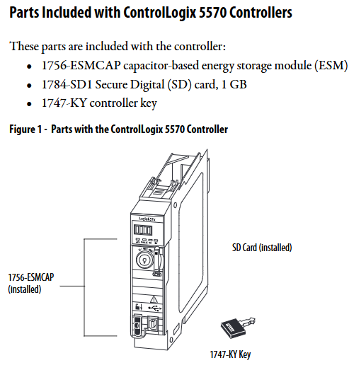
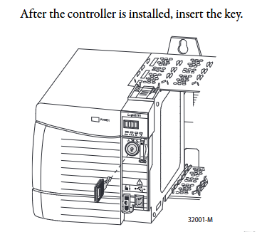
(1) Key installation of ControlLogix 5570
**Chassis and power supply pre installation * *: Chassis and power supply need to be installed according to the manuals "1756-IN621 (Chassis)" and "1756-IN619 (Power Supply)" first.
Controller insertion: Align the upper and lower rails of the chassis, slide in to the buckle lock, and ensure that it is flush with adjacent modules; Attention should be paid to the risk of electric arc in explosion-proof environment during live plugging and unplugging. It is recommended to perform power-off operation.
ESM installation: Align with the tongue and grain slot and push it into the buckle for fixation. After installation, start charging (up to 2 minutes, the status screen displays "CHRG"). Do not turn off the power before charging is complete, otherwise the program may be lost.
SD card operation: Open the SD card card, insert the 1784-SD1/SD2 card (recommended original card to avoid data damage), and press it until the card buckle locks; Before removal, it is necessary to confirm that the SD indicator light is off and that the explosion-proof environment requires power-off operation.
(2) Key installation of ControlLogix 5560
Battery installation: Series A uses 1756-BA1/BATM, Series B uses 1756-BA2, connect the positive and negative poles (red+black -), write the replacement date and paste it on the inside of the cabinet door.
CompactFlash card operation: Series A needs to lift the locking clip to insert, Series B needs to push open the buckle and insert, and before removing, confirm that the OK indicator light is green.
3. Hardware security specifications
Static protection: Before operation, touch grounded objects to discharge electricity, wear a grounding wristband, avoid touching connector pins and internal circuits, and use anti-static workstation storage devices.
Explosion proof requirements: In Class I Zone 2 (Groups A-D) environments, equipment/components can only be plugged in and out after power failure or confirmation of non hazardous areas; It is prohibited to replace non certified components, and batteries must be replaced in non hazardous areas.
Software configuration and firmware upgrade
1. Essential software and version requirements
Different controller models need to be matched with specific software versions, and the core requirements are as follows:
Controller model Studio 5000 environment minimum version RSLogix 5000 minimum version RSLinx Classic minimum version
1756-L71/L72/L73 and other V21.00.00 V20.01.02 V2.59.00
1756-L61/A - V12.06.00 any version
1756-L63XT/B - V13.04.00 V2.55.00
2. Firmware upgrade method
Supports two methods: ControlFLASH software and AutoFlash (built-in in Logix Designer). The steps are as follows:
(1) ControlFLASH upgrade
Connect the controller (USB/Ethernet), start ControlFLASH, select the controller model and network driver.
Select the target firmware version (download the matching version from the official website to avoid file corruption), click "Finish" to start the upgrade, and do not turn off the power during the process.
- OMRON
- ABB
- General Electric
- EMERSON
- Honeywell
- HIMA
- ALSTOM
- Rolls-Royce
- MOTOROLA
- Rockwell
- Siemens
- Woodward
- YOKOGAWA
- FOXBORO
- KOLLMORGEN
- MOOG
- KB
- YAMAHA
- BENDER
- TEKTRONIX
- Westinghouse
- AMAT
- AB
- XYCOM
- Yaskawa
- B&R
- Schneider
- KONGSBERG
- NI
- WATLOW
- ProSoft
- SEW
- ADVANCED
- Reliance
- TRICONEX
- METSO
- MAN
- Advantest
- STUDER
- DANAHER MOTION
- Bently
- Galil
- EATON
- MOLEX
- DEIF
- B&W
- ZYGO
- Aerotech
- DANFOSS
- Beijer
- Moxa
- Rexroth
- Johnson
- WAGO
- TOSHIBA
- BMCM
- SMC
- HITACHI
- HIRSCHMANN
- Application field
- XP POWER
- CTI
- TRICON
- STOBER
- Thinklogical
- Horner Automation
- Meggitt
- Fanuc
- Baldor
- SHINKAWA
- Other Brands
- UniOP
- KUKA
- Iba
- Beckhoff
-
 Basler SSR 125-12 Regulator
 -
 Basler MOC2599 Motor Pot
 -
 Basler BE1-DFPR Feeder Relay
 -
 Basler CBS 305 Current Boost
 -
 Basler BE1-25 AutoSync
 -
 Basler MVC 300 Voltage Control
 -
 Basler BE3-25A AutoSync
 -
 Basler KR7FF Static Regulator
 -
 Basler 90-49000-100 Regulator
 -
 Basler 880 kVA Dry Type Transformer Specs
 -
 Basler Electric BE1-25 Sync-Check Relay Specs
 -
 Basler SSR 125-12 Voltage Regulator Specs
 -
 Basler Electric BE1-851 Overcurrent Relay Review
 -
Basler Electric 149D930G02 Control Sub-Assembly
-
 Basler Electric BE1-81O/UT Frequency Relay Specs
 -
 Basler Electric BE1-51/27C Overcurrent Relay
 -
 Basler Electric 149D956G02 Industrial Component
 -
Basler Electric BE1-51A Overcurrent Relay Specs
-
 Basler Electric BE1-40Q Loss of Excitation Relay
 -
 Basler DECS-200 Excitation Control System
 -
 Basler DECS-200 Voltage Regulator 56-277V AC / 125V DC
 -
 Basler BE1-87T Transformer Differential Relay
 -
 Basler RDP-110-S1 Protection Relay
 -
 Basler BE1-700V Digital Protective Relay
 -
 Basler BE1-951 Overcurrent Protection System
 -
 Basler DECS-300 Digital Excitation Control
 -
 Basler DECS-200 Digital Excitation Control
 -
 Basler DECS-200-1C Excitation Control System
 -
Basler DECS-200-1L Digital Excitation Control
-
 Basler Electric BE1-GPS Generator Protection System
 -
Basler Electric DECS-200-1C Digital Excitation Controller
-
 Basler Electric DECS125-15 Excitation Control with Power Module
 -
 Basler Electric BE1-87G Differential Relay
 -
 Basler Electric BE1-11 Protection System I5A3M2P2N0EA00
 -
Basler Electric DECS-200-1C Excitation Control System
-
Basler Electric BE1-11g Generator Protection Relay
-
 Basler Electric DECS 125-15-B2C1 V2.0.9 Excitation Control
 -
 Basler Electric BE1-81O/UT3ED1JA7N2F Frequency Relay
 -
Basler Electric BE1-81O/UT3EE1YB7N1F Frequency Relay
-
 Basler Electric DECS-200-1L Digital Excitation Control System
 -
Basler DECS125-15-B2C1 Excitation Control
-
 Basler 9507900205 SSR Retrofit Voltage Regulator
 -
 Basler BE2000E Digital Voltage Regulator
 -
 Basler BE1-GPS Generator Protection System
 -
Basler DECS-250-CN1CN1N Digital Excitation Control
-
 Basler DGC-2020 Genset Controller
 -
 Basler BE1-81O UT3ED1LA7N0F Frequency Relay (Variant)
 -
 Basler BE1-81O UT3EE1YA9S0F Frequency Relay (Variant)
 -
Basler BE1-81O Over/Under Frequency Relay
-
Basler DECS125-15 Digital Excitation Control
-
Basler Electric BE1-951 Overcurrent Protection System
-
 Basler Electric BE1-700V Digital Protective Relay
 -
 Basler Electric APR63-5 Automatic Voltage Regulator
 -
Basler Electric BE1-851 Overcurrent Protection System
-
Basler Electric DECS-250-LN1SN1N Excitation Control
-
 Basler Electric BE1-87T Transformer Differential Relay
 -
Basler Electric DECS-200-1L Excitation Control System
-
 Basler Electric 9310300100 DECS-300 Excitation Control
 -
 Basler Electric SSE-N 125-4.5KW Shunt Exciter Regulator
 -
 Basler Electric DGC-2020HD-5NS1DNSBA Genset Controller
 -
Basler Electric BE1-81-O/UT3EE1JB7N1F Frequency Relay
-
Basler Electric BE1-81T1EE1WA0N1F Frequency Relay
-
 Basler Electric BE1-25M1EA6PN5R1F Sync-Check Relay
 -
 Basler Electric BE1-GPS Generator Protection System
 -
Basler Electric DECS-250-LN1SN1N Excitation Control Rev V
-
 Basler Electric DECS-250-CN2CN1N Excitation Control
 -
Basler Electric BE1-50/51B-207 Overcurrent Relay
-
Basler Electric DECS-300-C0N0 Excitation Control System
-
Basler Electric DECS-200 Digital Excitation Control System
-
Basler Electric DECS-250-LN1CN1N Excitation Unit
-
Basler Electric DECS-250 LN2SA1D Excitation Unit Specs
-
Basler Electric BE1-87T Transformer Relay Review
-
Basler Electric BE1-11 Protection System
-
Basler Electric BE1-GPS100-E4N1H1N Protection System
-
 Allen-Bradley 442G-MABH-R Safety Module
 -
 Beckhoff CX1030-0111 PLC Assembly Profile
 -
 FANUC IC693CPU364 PLC Module
 -
 Orange Denmark Type 200816 220 PLC Specs
 -
 OMRON C200H-SNT31 Sysmac PLC Module
 -
 Allen Bradley 20AB022A3AYNANC0 PowerFlex 70
 -
 OMRON C200HW-PCU01 Position Control Unit
 -
 ABB AO845A-eA Analog Output Module
 -
 OMRON CJ1M-CPU22 CPU Unit
 -
 Allen Bradley 100-E265ED11 Contactor
 -
 Honeywell 51304511-100 Interface Module
 -
 SOLEXY BXF3S0101N0018 Gateway Module
 -
 OMRON CJ2H-CPU65 CPU Unit
 -
 Automation Direct GS2-45P0 AC Drive
 -
 M68-2000 2-Axis Motion CNC Controller
 -
 OMRON CJ1M-CPU11 V3.0 PLC CPU Unit
 -
 OMRON CJ1W-NC413 4-Axis Positioning Controller
 -
 OMRON 3G2A3-PRO16 Programming Console HMI
 -
 Siemens 3VT8440-2AA04-2GA2 Molded Case Circuit Breaker
 -
 Siemens 3RT5045 Contactor Series
 -
 OMRON C200HS-CPU01-E SYSMAC PLC Controller
 -
 OMRON C500-NC103-E Positioning Control Unit
 -
 OMRON CJ1W-TC001 Temperature Control Unit
 -
 OMRON NJ301-1100 NJ-PA3001 PLC System EtherCAT
 -
 Pilz 773100 M1P Safety Relay Base Unit
 -
 Siemens SINUMERIK 840D SL NCU 720.3B with PLC 317-3 PN/DP
 -
 Siemens 6AV6618-7GD01-3AB0 HMI Panel
 -
 OMRON F150-C15E-3 Vision Mate Controller PLC Overview
 -
 Mitsubishi MELSEC A Series PLC System A63P A3ACPU A616AD A68RD3
 -
 M68-2000 2 Axis Motion Controller SCE SERVO CNC
 -
 OMRON FZ-S2M PLC Camera Vision System
 -
 VISOLUX SLVA-4K PLC Module from Elektronik GmbH
 -
 OMRON CJ1M-CPU23 V2.0 PLC CPU Unit
 -
 ABB AI86-16CHF PCB Card 5761751-9 B Specifications
 -
 Allen-Bradley 100-D140ZJ22L Contactor Overview
 -
 Merlin Gerin PB80 PLC Rack
 -
 WEIR WE203 Power Supply PLC
 -
 OMRON NX-TS3102 Temperature Input Unit
 -
 Siemens 6ES7146-6FF00-0AB0 I/O Module
 -
 Fanuc A16B-3300-0057 Circuit Board
 -
 OMRON CJ1W-IDP01 Input Module
 -
 Siemens 6FX2007-1AD13 Handheld Unit
 -
 Gems EM54 PLC Module PCB
 -
 Beckhoff CX2030-0121 Embedded PC CPU
 -
 OMRON NJ301-1100 Machine Automation Controller
 -
 Biesse Rover CNI PLC 2153 030 7146.30 Numerical Control Module
 -
 OMRON CJ1W DA08V Analog Output Module
 -
 OMRON CS1D ETN21D Ethernet Module
 -
 Allen Bradley 1768 L43 CompactLogix Controller
 -
 Schneider TWDLMDA40DTK Twido PLC Module
 -
 Mitsubishi NZ2EX2B 60AD4 Analog Input Module
 -
 OMRON NS8 TV00B V2 Touch Display Panel
 -
 Mitsubishi AY71 CMOS TTL Output Module
 -
 OMRON C500 CPU11 E Processor Module


