
Rockwell Automation ControlLogix 5570 and 5560 controllers
Features ControlLogix 5570 ControlLogix 5560
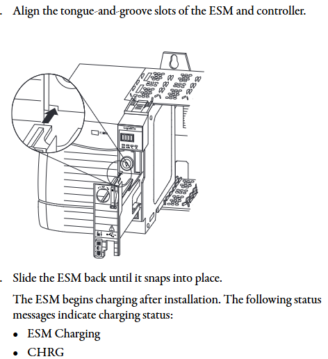
Power Supply and Memory Backup Energy Storage Module (ESM) Lithium Battery (1756-BA1/BA2/BATM)
Built in communication port USB 2.0 (temporary programming only, cable length ≤ 3m, no hub) RS-232 serial port
The maximum number of connections is 500 and 250
Non volatile storage SD card (standard 1784-SD1 1GB) CompactFlash card (available separately)
Status display: 4-line scrolling text screen+4 indicator lights, 6 indicator lights (no text screen)
Representative models 1756-L71/L72/L73/L74/L75 1756-L61/L62/L63/L64/L65
After the upgrade is completed, the controller automatically restarts and the confirmation status screen displays the new firmware version (such as "Rev 30.011").
(2) AutoFlash upgrade
Create a project in Logix Designer, click on "Who Active" to find the target controller, and select "Update Firmware".
Select the firmware file path and version, confirm that the controller is in "Remote Program" mode and there are no uncleared faults, and click "Update".
During the upgrade process, the progress is displayed (5570 points for "update count/block count", 5560 only displays "block count"), and the firmware version is verified after completion.
3. Memory and storage configuration
5570 series: SD cards are used to store project and fault logs, supporting three modes: "power on load", "load when memory is damaged", and "user triggered load". Locking the SD card can prevent firmware from being overwritten.
5560 series: The CompactFlash card needs to be configured with the "store/load" parameter in Logix Designer, supporting program backup and recovery. When replacing the battery, ensure that there is a backup in the card to prevent data loss.
Communication network configuration
1. Supported communication protocols and modules
The controller supports multiple types of industrial networks and requires corresponding communication modules. The core configuration is as follows:
Network type, communication module model, core function, maximum number of connections/bandwidth limit
EtherNet/IP 1756-ENBT/EN2TR/EN3TR supports production and consumption tags, I/O control, and HMI communication. 1756-EN3TR supports 256 movements in 128 axes (EN2T/EN2TR); 128 (ENBT)
ControlNet 1756-CNB/CN2/CN2R/CN2RXT deterministic real-time communication, supporting 64 redundant media (CN2R/CN2RXT) (CNB/CNBR); 128 (CN2/CN2R)
DeviceNet 1756-DNB connects distributed I/O and drivers, supports scanning list configuration with 124 DINT input/123 DINT output
Data Highway Plus (DH+) 1756-DHRIO/DHRIOXT connects PLC-5/SLC controllers, supporting 32 sites at 57.6/115.2/230.4 kbps rates
HART 1756-IF8H/OF8H analog I/O+digital signal superposition, supports direct connection to HART transmitter for device diagnosis
2. Key steps for communication configuration
(1) EtherNet/IP configuration
Add modules such as 1756-EN2T in the "I/O Configuration" of Logix Designer and set the IP address (supporting BOOTP/DHCP allocation).
Configure "Production/Consumption Tags": Production tags need to specify the number of consumers, while consumption tags need to match the production tag data type and RPI (Request Packet Interval).
Remote I/O configuration: Reduce the number of connections through "rack optimization connections", and a single connection can cover the entire remote rack I/O.
(2) Serial Communication (5560 Series)
Connect the 1756-CP3 serial port cable, configure the "RS-232 DF1 device driver" in RSLinx, and select the "Logix 5550/CompactLogix" device type.
Supporting protocols: DF1 master-slave/point-to-point/wireless modem, DH-485, ASCII, Modbus (requiring MSG instruction programming), ASCII protocol requires configuring buffer size (1-4096 bytes) and termination characters.
Programming and Application Development
1. Control program structure
The Logix 5000 control program consists of a three-level structure of "task program routine", with the following core rules:
Tasks (up to 32):
Continuous task (1): lowest priority, utilizing idle CPU time for cyclic execution.
Periodic task: Execute at set intervals (0.1~2000000ms), priority 1~15 (highest 1).
Event task: triggered by triggering conditions (such as I/O status changes, consumption tag triggers) for execution.
Program (up to 1000 per task, V24+): Contains local tags, parameters, main routines, fault routines, supports "scheduled execution" (executed in sequence) and "unplanned execution" (only verified and not running).
Routine: executable code written in a single programming language, supporting ladder diagrams (LD), function block diagrams (FBD), structured text (ST), and sequential function diagrams (SFC).
2. Core programming functions
(1) Production/Consumption Tags (Interlock Data)
Production label: One controller releases data, and multiple controllers (up to 32) consume it simultaneously. It must be on the same network (not bridged across networks), and the data type and array dimension must be consistent.
Connection calculation: The production label occupies "number of consumers+1" controller connection, the consumption label occupies 1 connection, and the communication module occupies an additional 1 connection.
(2) MSG instruction (message communication)
Supports types such as "CIP Data Table Read/Write", "PLC-5/SLC Communication", "General CIP", etc. It can cache connections (optimize speed during repeated execution, up to 32 cache connections) or non cache connections (release connections after execution).
Block Transfer requires the configuration of a "request/response" data area, which is suitable for high-speed counters, frequency converters, and other devices.
- OMRON
- ABB
- General Electric
- EMERSON
- Honeywell
- HIMA
- ALSTOM
- Rolls-Royce
- MOTOROLA
- Rockwell
- Siemens
- Woodward
- YOKOGAWA
- FOXBORO
- KOLLMORGEN
- MOOG
- KB
- YAMAHA
- BENDER
- TEKTRONIX
- Westinghouse
- AMAT
- AB
- XYCOM
- Yaskawa
- B&R
- Schneider
- KONGSBERG
- NI
- WATLOW
- ProSoft
- SEW
- ADVANCED
- Reliance
- TRICONEX
- METSO
- MAN
- Advantest
- STUDER
- DANAHER MOTION
- Bently
- Galil
- EATON
- MOLEX
- DEIF
- B&W
- ZYGO
- Aerotech
- DANFOSS
- Beijer
- Moxa
- Rexroth
- Johnson
- WAGO
- TOSHIBA
- BMCM
- SMC
- HITACHI
- HIRSCHMANN
- Application field
- XP POWER
- CTI
- TRICON
- STOBER
- Thinklogical
- Horner Automation
- Meggitt
- Fanuc
- Baldor
- SHINKAWA
- Other Brands
- UniOP
- KUKA
- Iba
- Beckhoff
-
 Basler Electric BE1-81O/UT3ED1JA7N2F Frequency Relay
 -
 Basler Electric BE1-81O/UT3EE1YB7N1F Frequency Relay
 -
 Basler Electric DECS-200-1L Digital Excitation Control System
 -
 Basler DECS125-15-B2C1 Excitation Control
 -
 Basler 9507900205 SSR Retrofit Voltage Regulator
 -
 Basler BE2000E Digital Voltage Regulator
 -
 Basler BE1-GPS Generator Protection System
 -
 Basler DECS-250-CN1CN1N Digital Excitation Control
 -
 Basler DGC-2020 Genset Controller
 -
 Basler BE1-81O UT3ED1LA7N0F Frequency Relay (Variant)
 -
 Basler BE1-81O UT3EE1YA9S0F Frequency Relay (Variant)
 -
Basler BE1-81O Over/Under Frequency Relay
-
 Basler DECS125-15 Digital Excitation Control
 -
 Basler Electric BE1-951 Overcurrent Protection System
 -
 Basler Electric BE1-700V Digital Protective Relay
 -
 Basler Electric APR63-5 Automatic Voltage Regulator
 -
 Basler Electric BE1-851 Overcurrent Protection System
 -
 Basler Electric DECS-250-LN1SN1N Excitation Control
 -
 Basler Electric BE1-87T Transformer Differential Relay
 -
 Basler Electric DECS-200-1L Excitation Control System
 -
 Basler Electric 9310300100 DECS-300 Excitation Control
 -
 Basler Electric SSE-N 125-4.5KW Shunt Exciter Regulator
 -
 Basler Electric DGC-2020HD-5NS1DNSBA Genset Controller
 -
Basler Electric BE1-81-O/UT3EE1JB7N1F Frequency Relay
-
Basler Electric BE1-81T1EE1WA0N1F Frequency Relay
-
 Basler Electric BE1-25M1EA6PN5R1F Sync-Check Relay
 -
 Basler Electric BE1-GPS Generator Protection System
 -
Basler Electric DECS-250-LN1SN1N Excitation Control Rev V
-
 Basler Electric DECS-250-CN2CN1N Excitation Control
 -
 Basler Electric BE1-50/51B-207 Overcurrent Relay
 -
Basler Electric DECS-300-C0N0 Excitation Control System
-
Basler Electric DECS-200 Digital Excitation Control System
-
Basler Electric DECS-250-LN1CN1N Excitation Unit
-
Basler Electric DECS-250 LN2SA1D Excitation Unit Specs
-
Basler Electric BE1-87T Transformer Relay Review
-
Basler Electric BE1-11 Protection System
-
Basler Electric BE1-GPS100-E4N1H1N Protection System
-
 Allen-Bradley 442G-MABH-R Safety Module
 -
 Beckhoff CX1030-0111 PLC Assembly Profile
 -
 FANUC IC693CPU364 PLC Module
 -
 Orange Denmark Type 200816 220 PLC Specs
 -
 OMRON C200H-SNT31 Sysmac PLC Module
 -
 Allen Bradley 20AB022A3AYNANC0 PowerFlex 70
 -
 OMRON C200HW-PCU01 Position Control Unit
 -
 ABB AO845A-eA Analog Output Module
 -
 OMRON CJ1M-CPU22 CPU Unit
 -
 Allen Bradley 100-E265ED11 Contactor
 -
 Honeywell 51304511-100 Interface Module
 -
 SOLEXY BXF3S0101N0018 Gateway Module
 -
 OMRON CJ2H-CPU65 CPU Unit
 -
 Automation Direct GS2-45P0 AC Drive
 -
 M68-2000 2-Axis Motion CNC Controller
 -
 OMRON CJ1M-CPU11 V3.0 PLC CPU Unit
 -
 OMRON CJ1W-NC413 4-Axis Positioning Controller
 -
 OMRON 3G2A3-PRO16 Programming Console HMI
 -
 Siemens 3VT8440-2AA04-2GA2 Molded Case Circuit Breaker
 -
 Siemens 3RT5045 Contactor Series
 -
 OMRON C200HS-CPU01-E SYSMAC PLC Controller
 -
 OMRON C500-NC103-E Positioning Control Unit
 -
 OMRON CJ1W-TC001 Temperature Control Unit
 -
 OMRON NJ301-1100 NJ-PA3001 PLC System EtherCAT
 -
 Pilz 773100 M1P Safety Relay Base Unit
 -
 Siemens SINUMERIK 840D SL NCU 720.3B with PLC 317-3 PN/DP
 -
 Siemens 6AV6618-7GD01-3AB0 HMI Panel
 -
 OMRON F150-C15E-3 Vision Mate Controller PLC Overview
 -
 Mitsubishi MELSEC A Series PLC System A63P A3ACPU A616AD A68RD3
 -
 M68-2000 2 Axis Motion Controller SCE SERVO CNC
 -
 OMRON FZ-S2M PLC Camera Vision System
 -
 VISOLUX SLVA-4K PLC Module from Elektronik GmbH
 -
 OMRON CJ1M-CPU23 V2.0 PLC CPU Unit
 -
 ABB AI86-16CHF PCB Card 5761751-9 B Specifications
 -
 Allen-Bradley 100-D140ZJ22L Contactor Overview
 -
 Merlin Gerin PB80 PLC Rack
 -
 WEIR WE203 Power Supply PLC
 -
 OMRON NX-TS3102 Temperature Input Unit
 -
 Siemens 6ES7146-6FF00-0AB0 I/O Module
 -
 Fanuc A16B-3300-0057 Circuit Board
 -
 OMRON CJ1W-IDP01 Input Module
 -
 Siemens 6FX2007-1AD13 Handheld Unit
 -
 Gems EM54 PLC Module PCB
 -
 Beckhoff CX2030-0121 Embedded PC CPU
 -
 OMRON NJ301-1100 Machine Automation Controller
 -
 Biesse Rover CNI PLC 2153 030 7146.30 Numerical Control Module
 -
 OMRON CJ1W DA08V Analog Output Module
 -
 OMRON CS1D ETN21D Ethernet Module
 -
 Allen Bradley 1768 L43 CompactLogix Controller
 -
 Schneider TWDLMDA40DTK Twido PLC Module
 -
 Mitsubishi NZ2EX2B 60AD4 Analog Input Module
 -
 OMRON NS8 TV00B V2 Touch Display Panel
 -
 Mitsubishi AY71 CMOS TTL Output Module
 -
 OMRON C500 CPU11 E Processor Module
 -
 OMRON CJ1W PTS51 Temperature Input Module
 -
 Siemens 6SL3100-1DE22-0AA1 600V DC Supply
 -
 OMRON CJ1M-CPU23 PLC CPU 9‑Pin Serial
 -
 Schlumberger IMT4N 24‑250VAC 48‑230VAC PLC Timer
 -
 OMRON CJ1M-CPU22 PLC CPU Unit V2.0
 -
 Allen‑Bradley 2711P-B7C6D2 Touch Screen PanelView
 -
 ADSP-2181KST-160 Analog Devices DSP IC Specs
 -
 Schneider LC1F400 400A Contactor Specifications
 -
 Yaskawa SGDH-10DE-OY 1kW 400V Servo Drive
 -
 Schneider TM262L10MESE8T M262 PLC 5ns Inst
 -
 Mitsubishi AA104VJ05 10.4in LCD Panel Specs
 -
 Allen Bradley 1761-L32BWA MicroLogix 1000 PLC
 -
 Siemens 6ES7431-7KF00-0AB0 Analog Input Module
 -
 Allen Bradley 1769-OB16 Output Module
 -
 Siemens 6ES7131-1BL12-0XB0 Input Module
 -
 Beckhoff EP7041-3002 EtherCAT Box Module
 -
 Siemens RK7243-2AA30-0XB0 Communication Module
 -
 Siemens 4AM5742-8DD40-0FA0 Transformer
 -
 Siemens 3TK2834-1BB40 Safety Relay
 -
 Brother BAS 311 Sewing Machine Circuit Board
 -
Yaskawa SGDH-10DE-OY Servo Driver
-
 OMRON C60H C6DR DE V1 Sysmac PLC
 -
 MITSUBISHI ELECTRIC A2ACPU21 S1 CPU Module
 -
 ABB BAILEY INNPM12 Network Process Module
 -
 HONEYWELL 620 0073C IPC PLC Module
 -
 Mitsubishi 15050 PR02B PLC Circuit Board
 -
 SIEMENS 6SY7000 0AC37 Drive Control Module
 -
 OMRON TJ2 ECT16 Traxial EtherCAT Controller
 -
 GE Fanuc IC698PSD300D Power Supply Module
 -
 Texas Instruments Series 505 16 Position Base
 -
 OMRON YASKAWA SGDH 10DE OY Servo Drive
 -
 Allen‑Bradley 440G-MT Safety Interlock Switch Specs
 -
 Rubycon PD27A 24V 8A Power Supply Module
 -
 SK-H1-GDB1-F11D PLC Gate Driver Board Kit
 -
 VIPA 441-4UA14 451-4UA14 PLC Module Rack
 -
 Mitsubishi FX5U-80MT ESS PLC Controller Specs
 -
 Mitsubishi Q64TCRTN Temperature PLC Module


