
WOODWARD DSLC-2 Digital Synchronizer and Load Control
WOODWARD DSLC-2 Digital Synchronizer and Load Control
Introduction
The Woodward DSLC-2 digital synchronizer and load control is an advanced microcomputer control device designed specifically for three-phase AC generators, integrating multiple functions such as synchronization control, load sensing, load distribution, dead bus closure, reactive power/power factor control, and process control. This article is based on Woodward's official 37443J technical manual (software version 1.15xx), providing a comprehensive analysis of the core functions, technical features, installation configuration, and operational applications of the device. The aim is to provide engineers, technicians, and operations personnel with a detailed reference guide.
1、 Product Overview and Core Features
1.1 Product positioning
DSLC-2 is a direct upgrade product of Woodward's classic DSLC series, suitable for various grid connected or islanded operating generator sets. Its design supports parallel operation and control of up to 32 generator sets, achieving seamless communication between DSLC-2 and MSLC-2 (main station load control unit) through a dedicated Ethernet system.
1.2 Main functional modules
Synchronizer function:
Supports two modes: phase matching or slip frequency synchronization.
Capable of automatic dead bus closure, conducting locking negotiation through communication network to prevent multiple devices from closing simultaneously.
Integrated voltage matching, automatic reclosing, automatic resynchronization, and synchronization timeout alarm functions.
Load control function:
Support droop control, base load control, and equal power load distribution mode.
Provide adjustable ramp loading/unloading to achieve disturbance free switching.
Integrated reverse power protection, load switch, and frequency fine-tuning functions.
Process control function:
Cascade PID process controller, suitable for applications such as cogeneration, inlet/outlet control, pressure or liquid level control, etc.
Supports analog input (process signal) and internal digital reference, and can be remotely set.
Reactive power/power factor control function:
Control the reactive power or power factor of the generator in the grid connected system.
Support reactive power sharing (during islanding operation) and voltage fine-tuning function.
Provide voltage range alarm and high/low limit protection.
Communication and network functions:
Equipped with dual Ethernet ports (network A and B), supporting redundant communication.
Network A is dedicated to DSLC-2/MSLC-2 internal communication (UDP protocol).
Network B supports Modbus TCP/IP for communication with the upper computer (PLC/DCS).
Additionally, RS-485 interface is provided to support Modbus RTU protocol.
2、 System architecture and installation points
2.1 Hardware Installation
Dimensions: 227 mm × 250 mm × 84 mm, using panel installation method.
Environmental requirements: The working temperature range is -40 ° C to+70 ° C, and direct exposure to water sources, condensation environments, and strong electromagnetic interference should be avoided.
Power requirement: 12/24 VDC (range 8-40 VDC), it is recommended to use slow melting fuses (6A) or miniature circuit breakers for protection.
Grounding protection: It is necessary to connect a protective earth wire (PE) with a wire diameter of not less than 2.5 mm ².
2.2 Wiring specifications
Voltage measurement:
Generator voltage measurement supports 3-phase 4-wire (with neutral point), 3-phase 3-wire, and 3-phase 4-wire open delta connections.
Bus voltage measurement supports 1-phase 2-wire (phase to phase or phase to neutral point) and 3-phase measurement of auxiliary bus.
Attention: 120V and 480V input terminals cannot be used simultaneously, and the correct terminals should be configured according to the rated voltage of the PT secondary side.
Current measurement:
Support three-phase or single-phase current transformer input, ensuring that one end of the CT secondary side is grounded.
When wiring, attention should be paid to the power measurement direction and display symbol (positive for power generation, negative for reverse power).
Discrete input:
Supports positive or negative polarity signals, but all inputs must be of the same polarity.
The input functions include: operation, circuit breaker assistance, voltage rise/fall, load rise/fall, base load, unloading, process control, ramp pause, and section number selection.
Relay output:
There are a total of 12 relay outputs, including alarm, load switch, high and low limit, circuit breaker opening and closing, and voltage rise/fall.
The output contact capacity is 250VAC/DC, 2A.
Analog input/output:
Provide 3 analog inputs (remote load reference, process signal, reactive load).
2-channel analog output (speed bias, voltage bias), supporting multiple signal types such as 0-20mA, 4-20mA, 0-10V, etc., can be configured as voltage or PWM output through jumper wires.
2.3 Communication Interface
RS-232: Used to connect Woodward ToolKit configuration software.
RS-485: Supports Modbus RTU half duplex or full duplex communication.
Ethernet (RJ-45): Network A (UDP+Modbus TCP), Network B (Modbus TCP, optional redundant UDP).
The communication protocol supports Woodward Private Protocol (ServLink) and standard Modbus.
3、 Detailed explanation of software configuration and parameters
3.1 Configuration Tool - Woodward ToolKit
Version requirement: V6.4.1 or higher version is required.
Connection method: It can be connected through RS-232 serial port or Ethernet (recommended network A).
Function: Provides visual monitoring, parameter configuration, trend recording, diagnosis, and firmware management functions.
3.2 Analysis of Key Parameter Menu
3.2.1 Synchronizer Configuration (Menu 1)
Synchronization mode: optional shutdown, synchronization, allow, check, run, automatic shutdown, etc.
Phase matching/slip frequency: Users can choose according to their application requirements.
Dead bus closure: After activation, the device automatically detects the dead bus and negotiates closure permissions.
Phase angle compensation: configurable ± 180 ° compensation value, used to correct phase deviation caused by transformer wiring.
3.2.2 Load Control (Menu 2)
Frequency control mode: PID analog control, three position controller or off.
Load control modes: droop, base load, load distribution, process control, etc.
Slope rate: The loading, unloading, and lifting/lowering reference rates can be independently configured.
Load allocation gain: Adjust the response speed and stability of load allocation.
3.2.3 Process Control (Menu 3)
PID parameters: Proportional, integral, and derivative gains are adjustable.
Process reference source: internal settings or remote analog input.
High and low limit alarm: It can set the high and low limit values of the process signal and enable the alarm.
3.2.4 Reactive Power/Power Factor Control (Menu 4)
Control mode: reactive power control, power factor control, or shutdown.
Voltage control mode: PID analog control or three position controller.
Reactive power allocation gain: Adjust the reactive power allocation performance when multiple machines are connected in parallel.
3.2.5 System Configuration (Menu 5)
Equipment number: 1-32, must be unique.
Segment number configuration: Supports 8 bus segments, which can be input through discrete quantities or automatically recognized.
PT/CT parameters: The transformer ratio must be accurately set to ensure measurement accuracy.
Communication mode: Single network or redundant Ethernet mode.
3.2.6 Analog Input/Output (Menu 6)
Input signal type: optional current and voltage signals, supporting linear calibration.
Output signal range: Multiple standard signal ranges or custom ranges can be configured.
Filter constant: Optional filtering level, smooth output signal.
3.2.7 System Management (Menu 5.2)
Password protection: Supports 5 levels of access permissions (user, service, temporary debugging, debugging, super debugging).
Factory settings recovery: default parameters can be restored through password protection.
Indicator light test: One click test of the front panel LED status.
4、 Advanced features and application scenarios
4.1 Parallel connection and segmented control of multiple units
DSLC-2 supports up to 32 units+16 MSLC-2 to form a complex power grid.
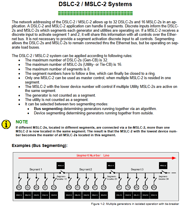
Segmented operation: By using discrete inputs (DI13-DI20) to identify the status of bus segments, independent or parallel operation between different segments can be achieved.
Load distribution: During islanding operation, precise allocation of active and reactive power is achieved through Ethernet communication.
4.2 Redundant Communication and System Reliability
Dual network redundancy: Networks A and B can be configured in redundancy mode to improve communication reliability.
Lost member detection: When communication between devices in the network is interrupted, the system automatically switches to droop mode to avoid losing control.
System update function: Network devices can be re identified and reconfigured through parameter or discrete input triggering.
4.3 Safety and Protection Functions
Electronic electrostatic protection: All electronic components are sensitive to static electricity and must strictly comply with ESD protection regulations.
Alarm and protection: Provide multiple alarms and protections for frequency, voltage, load, process, reverse power, etc.
Security Warning:
The prime mover must be equipped with an overspeed (over temperature/over pressure) shutdown device independent of the control system.
It is prohibited to use or modify the equipment beyond the prescribed scope, otherwise it may result in personal injury, property damage, and warranty failure.
5、 Maintenance and Diagnosis
5.1 Daily Maintenance
Regular inspection: wiring tightness, power supply voltage, communication status.
Software update: Check and update device firmware through ToolKit (requires authorized personnel to operate).
Counter management: It can record the operating hours and active/reactive energy of the generator, and supports manual reset and preset.
5.2 Fault diagnosis
ToolKit diagnostic page: provides real-time status monitoring, alarm recording, communication status, and device overview.
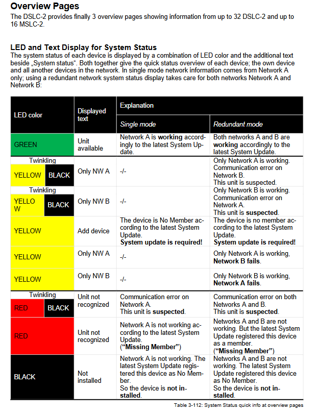
LED indication:
Synchronization Enable LED: Green indicates readiness for synchronization, red indicates voltage frequency window not met.
CPU normal "LED: Green indicates device ready, red indicates fault, flashing indicates system update.
Communication diagnosis: can detect network A/B errors, device mismatches, phase rotation mismatches, etc.
- OMRON
- ABB
- General Electric
- EMERSON
- Honeywell
- HIMA
- ALSTOM
- Rolls-Royce
- MOTOROLA
- Rockwell
- Siemens
- Woodward
- YOKOGAWA
- FOXBORO
- KOLLMORGEN
- MOOG
- KB
- YAMAHA
- BENDER
- TEKTRONIX
- Westinghouse
- AMAT
- AB
- XYCOM
- Yaskawa
- B&R
- Schneider
- KONGSBERG
- NI
- WATLOW
- ProSoft
- SEW
- ADVANCED
- Reliance
- TRICONEX
- METSO
- MAN
- Advantest
- STUDER
- DANAHER MOTION
- Bently
- Galil
- EATON
- MOLEX
- DEIF
- B&W
- ZYGO
- Aerotech
- DANFOSS
- Beijer
- Moxa
- Rexroth
- Johnson
- WAGO
- TOSHIBA
- BMCM
- SMC
- HITACHI
- HIRSCHMANN
- Application field
- XP POWER
- CTI
- TRICON
- STOBER
- Thinklogical
- Horner Automation
- Meggitt
- Fanuc
- Baldor
- SHINKAWA
- Other Brands
- UniOP
- KUKA
- Iba
- Beckhoff
- ADLINK
-
 Basler Electric BE1-700 Digital Protective Relay
 -
 Basler Electric SR8A-2B01B3A Static Voltage Regulator
 -
 Basler Electric SR4A-2B01B3E Static Voltage Regulator
 -
 Basler Electric 9017709102 PC Board
 -
Basler Electric SR4A-2B01B3A Static Voltage Regulator
-
 Basler Electric PRS-250 Veri-Sync Relay
 -
 Basler Electric 9066800102 Excitation Support System
 -
 Basler Electric BE1-87G Generator Differential Relay 9 1708 18 100
 -
 Basler Electric 36T865-2 BE03752001 Power Supply
 -
 Basler Electric M-300 149D940G02 Power Supply
 -
 Basler Electric ACA2040-25GM 4Mp 25Fps Area Scan Camera
 -
 Basler BE1-87G-S1A-A1C-A0N0 Differential Relay
 -
 Basler SR8A-2B06B3E Static Regulator SR8A2B06B3E
 -
 Basler SCP-210 Frequency Controller 9095400100
 -
 Basler BE1-59-A3E-A1J-N1N3F Overvoltage Relay BE159A3EA1JN1N3F
 -
 Basler 9 2011 11 100 Bracket Mounted Terminal Unit
 -
Basler 9 1606 00 101 Voltage Regulator
-
 Basler CBS-377 Current Boost System 9109600102
 -
 Basler 8650C72 Exciter Control Module PCB Rev 5
 -
 Basler C2EE1PA0N1F BE1-32R Reverse Power Relay
 -
 ADLINK HPCI-14S12U - Industrial Control Backplane 12PCI Backplane PCI-14S Passive Backplane
 -
-0010.png) ADLINK PCIe-GIE74C - image acquisition card 4-CH GigE Vision PoE+ Frame Grabber
ADLINK PCIe-GIE74C - image acquisition card 4-CH GigE Vision PoE+ Frame Grabber -
-0010_1.png) ADLINK PCI-8164 - control card 4-Axis Advanced Motion Controller Board
ADLINK PCI-8164 - control card 4-Axis Advanced Motion Controller Board -
 ADLINK PCIe-U304 - 4 Port USB3 PCIe Frame Grabbers USB Screw Hole Card
 -
 ADLINK PCI-9112 - Multi-Function Data Acquisition Card DAQ Card
 -
 ADLINK PCI-7432 - 51-12013-0A50 4-CH Isolated Numérique I/O PCI Cartes Digital I/O Card
 -
 ADLINK PCA-6106P3-0C1 REV.C1 - backplane 6-Slot Passive Backplane Board
 -
 ADLINK PCI-7224 - 24-CH Opto-Isolated Digital I/O PCI Board
 -
 ADLINK CPCI-7433R(G) - Digital Input Board Rear I/O CompactPCI Card
 -
 ADLINK EBP-13E4 - 51-46703-0A30 Industrial PC Backplane Passive Backplane
 -
 ADLINK PCIE-HDV62 - Image acquisition card High Definition Video Frame Grabber
 -
 ADLINK EBP-13E4 - 51-46703-0A30 Industrial Backplane Board Passive Backplane
 -
 ADLINK 90111-B1 / CPCI-6770 - PCB CPU MODULE CompactPCI Single Board Computer
 -
 ADLINK PCI-7248 - DATA ACQUISITION PCI CARD 48-CH Parallel Digital I/O Board
 -
 ADLINK PCI-7230 - 51-12003-0a50 board PCI7230 32-CH Isolated Digital I/O Card
 -
 ADLINK PCI2A000CB - 51-20000-0B30 Multi-Function DAQ Card Baseboard
 -
 ADLINK PCI-8134-005 - 4-Axis Motion Controller Card
 -
 ADLINK PCI-7224 - 24-CH Opto-Isolated Digital I/O PCI Card
 -
 ADLINK PCI-7434 - 64-CH Isolated Digital Output Card
 -
 ADLINK PCI-8132 - motion control card 2-Axis Servo & Stepper Controller
 -
 ADLINK PCI-8134 - Motion Controller PCI Card 4-Axis Controller Board
 -
 ADLINK PCI-8164 - Motion Control Card 51-12406-0A40 4-Axis Controller
 -
 ADLINK 51-12001-0C20 - Circuit Board Data Acquisition Interface Module Hardware
 -
 ADLINK NuPR0-840 - industrial control motherboard Full-Size PICMG CPU Board
 -
 ADLINK PCI-7444 - 51-12023-0A10 card 128-CH Isolated Digital Output Board
 -
 ADLINK PCI-1612B - data acquisition card 4-Port RS-232/422/485 Serial Communication Card
 -
 ADLINK PCI-6208V 009 - 8/16-CH 16-Bit Analog Output Cards PCB-I-E-482=6BX3
 -
 ADLINK NUPRO-935A/LV - industrial control motherboard Full-Size PICMG SBC Board
 -
 ADLINK PCI-9114DG - Multi-Function DAQ Card Data Acquisition PCI Card
 -
 ADLINK ACL-7130 - Data acquisition card Isolated Digital I/O Board
 -
 ADLINK ABX-6300D-4E1-BP - board ABX6300D4E1BP Video Interface Expansion Card
 -
 ADLINK CPCI-6940 - CPCI-6940/D1539/M16-0(EA)-000E 6U CompactPCI Processor Board
 -
 ADLINK NuPRO-760 - industrial control motherboard Half-Size PICMG SBC CPU Board
 -
 ADLINK IMB-M42H (G)-0020 - industrial control motherboard LGA1155 Micro-ATX Mainboard
 -
 ADLINK RTV-24 / PCI-MP4S - 51-12519-1C30 4-Channel Real Time Video Capture Board
 -
 ADLINK PCI-8134 - 4-Axis Servo & Stepper Motion Controller Card
 -
 ADLINK MXC-6101D - V.PC000.002.ST.00 Box PC Configurable Embedded Computer
 -
.png) ADLINK PCI-8134A - 51-12421-0A10 Motion Control Card 4-Axis Controller Card
ADLINK PCI-8134A - 51-12421-0A10 Motion Control Card 4-Axis Controller Card -
 ADLINK DIN-100S / DIN-100SA1 - Technology SCSI-II TB 100-PIN Terminal Block Board
 -
.png) ADLINK DIN-812M001 / DIN812M001 - 51-14034-0A1 51140340A1 Terminal Module Breakout Interface
ADLINK DIN-812M001 / DIN812M001 - 51-14034-0A1 51140340A1 Terminal Module Breakout Interface -
_1.png) ADLINK PCI-8164 - Servo motion control 4-Axis Advanced Controller Card
ADLINK PCI-8164 - Servo motion control 4-Axis Advanced Controller Card -
 ADLINK PCIe-GIE64 - Acquisition card GigE Vision PoE+ Frame Grabber
 -
 ADLINK M-302 - Industrial control motherboard ATX PC Board Mainboard
 -
 ADLINK PCI-8134 - Motion Controller PCI Card 4-Axis Controller Board
 -
 ADLINK PCI-RTV24 - Image capture card Analog Video Frame Grabber
 -
 ADLINK PCI-8102 - Motion control card 2-Axis Servo & Stepper Controller Board
 -
 ADLINK PCI-9112 REV.B1 - Card Multi-Function Data Acquisition Card
 -
 ADLINK HSI-DI32-M-N / HSL-TB32-M-DIN - Discrete I/O MODULE Distributed Automation Module System
 -
 ADLINK PCI-7296 - IO card REV.A3 96-CH Parallel Digital I/O Card
 -
-0020.png) ADLINK DIN-814P-A4 / 814Y - terminal board Motion Control Interface Block
ADLINK DIN-814P-A4 / 814Y - terminal board Motion Control Interface Block -
 ADLINK DIN-814P-A4 - 51-14056-0A10 PCB-I-E-2736=ZA01 Screw Terminal Board Breakout
 -
 ADLINK M-322 - motherboard Industrial Control Computer Mainboard
 -
 ADLINK NUPRO-406 REV:B1 - industrial control motherboard Full-Size PICMG CPU Board
 -
 ADLINK AMP-204C - card DSP-Based 4-Axis Advanced Pulse-Train Controller
 -
 ADLINK HPCI14S REV.B1 - industrial computer baseboard 14-Slot Passive Backplane
 -
 ADLINK PCI-7250 - 8-CH Relay Output & 8-CH Isolated DI PCI Card
 -
 ADLINK EBP-13E2 - baseplate Passive Backplane Industrial Computer Chassis Board
 -
 ADLINK LPCI-3488A - PCI-GPIB card 51-12801-0A30 acquisition card IEEE-488 Interface Board
 -
 ADLINK PCI-6216V-GL - 51-12201-0C30 16-CH 16-Bit Voltage Analog Output Card
 -
 ADLINK ACL-8454 - 16-CH Isolated Digital I/O & 4-CH Counter Card
 -
 ADLINK HPCI-9S7U - backplane Passive Backplane Compatible with NuPRO-A301 852 841 842
 -
 ADLINK DAQ-2010-007 - Simultaneous-Sampling Multi-Function Data Acquisition Card
 -
 ADLINK MP-C154 - 51-64205-0A10 Motion Control Card 4-Axis Controller Board
 -
 ADLINK MXE-202/mSSD16B/WiFi-BT - Matrix Rugged I/O Platform Embedded Fanless Computer
 -
 ADLINK CM-920-R-17 - PC/104-Plus Single Board Computer Module Intel Celeron M
 -
 ADLINK PCI-7250 NSMP - 8-CH Relay Output & 8-CH Isolated DI Card
 -
 ADLINK PCI-8164 - 4-Axis Motion Controller PCI Card W/ Cable and Breakout Box
 -
 ADLINK EMX-100 - Ethernet-based 4-axis Motion Controllers Distributed Motion Module
 -
.png) ADLINK PCI-8134A - Press control card 4-Axis Motion Controller Board
ADLINK PCI-8134A - Press control card 4-Axis Motion Controller Board -
 ADLINK M-845EG REV:3.2 - industrial motherboard Pentium 4 Socket 478 Micro-ATX
 -
 ADLINK PCI-9114A Rev A2 DG - card High-Resolution Multi-Function Data Acquisition Board
 -
 ADLINK IEC-915GV - REV 1.1 Industrial motherboard Socket 478 CPU Board
 -
 ADLINK PCI-9111DG(G) - Data Acquisition Card Multi-Function DAQ Card
 -
 ADLINK HPCI-15S10 REV:B2 - Industrial computer base plate Passive Backplane Board
 -
 ADLINK NuPR0-840 / NuPR0-840DV - industrial control motherboard Full-size PICMG CPU Board
 -
 ADLINK RTV-24 / PCI-MP4S - 51-12519-1C30 4-Channel Real Time Video Capture Board
 -
 ADLINK NUPRO-780 - industrial control motherboard Pentium III Single Board Computer
 -
 ADLINK PCI-7296 - 0050 card 96-CH Opto-Isolated Parallel DIO Card Set
 -
-0040.png) ADLINK NUPRO-780 - industrial control motherboard PICMG Full-Size SBC
ADLINK NUPRO-780 - industrial control motherboard PICMG Full-Size SBC -
 ADLINK PCI-7248 - 51-12006-0A3 002 Pci 7248 48-CH Parallel Digital I/O Card
 -
 ADLINK PCI-7230 - 32-CH Isolated Digital I/O Card
 -
 ADLINK AMP-204C - motion control card 4-Axis Advanced Controller Board
 -
.png) ADLINK PCI-1714UL - Card Ultra High-Speed 4-CH Simultaneous Sampling DAQ
ADLINK PCI-1714UL - Card Ultra High-Speed 4-CH Simultaneous Sampling DAQ -
 ADLINK NuPRO-E330 - industrial computer equipment motherboard PICMG 1.3 SHB SBC
 -
 ADLINK AMP-204C - DSP-Based 4-Axis Advanced Pulse-Train Motion Controller Module
 -
 ADLINK PCI-7256 - 001 51-12206-0A2 REV.A2 LPCI-7256 16-CH Latching Relay Output Card
 -
 ADLINK ND6050 - NUDAM DIGITAL I/0 MODULE Distributed I/O Unit
 -
 ASEM BM100 - Box PC Embedded Fanless Industrial Computer
 -
-3650.png) ADLINK PCI-7250 - PCI Acquisition Card 8-CH Relay Output & Isolated DI Board
ADLINK PCI-7250 - PCI Acquisition Card 8-CH Relay Output & Isolated DI Board -
 ADLINK PCI-8164 - Servo motion control 4-Axis Controller Card
 -
 Basler XR2002F Voltage Regulator 9139400101
 -
Basler 2D80367G23 DXCB De-Excitation Module 1200V 5000A
-
Basler SR4A-2B15B3A Static Regulator 120V 50/60Hz
-
 Basler SSR 125-12NF Static Regulator 9 1859 00 106
 -
 Basler BE1-BPR Breaker Protection Relay 9272000315
 -
 Basler SSR 63-12 Static Regulator 9 1859 00 101
 -
 Basler AEM-2020 Analog Expansion Module
 -
 Basler BE 25231-001 Transformer BE25231001
 -
Basler MVC 108 Manual Voltage Control 9037000102
-
 Basler PSS-100-Y5 Power System Stabilizer 0.1-5.0Hz
 -
Basler Electric BE1A-25-M1G-A6T-N4V1F Sync-Check Relay
-
 Basler Electric SR8A2B10B1A Static Voltage Regulator
 -
Basler Electric SR8A2B10B1A Static Voltage Regulator
-
Basler Electric SSR 125-12 Static Voltage Regulator 9185900102
-
 Basler Electric 90-73900-102 Power Supply (Westinghouse 2374A07G03)
 -
 Basler Electric 9400200117 Control Power Unit 12/24VDC 20W
 -
Basler Electric BE1-87G Solid State Generator Differential Relay
-
 Basler Electric BE1-32R Style C3ED1TA0S1F Solid State Protective Relay


