Watlow F4T Controller Installation and Failure
Environmental requirements for working temperature: -18~50 ℃ (-0~122 ° F); Storage temperature: -40~85 ℃; Humidity 0~90% RH without condensation
High voltage power supply specifications (F4TXX [1-4]): 85~264Vac 50/60Hz; Low voltage type (F4TXX [5-8]): 20.4~30.8Vac/dc
Power consumption 23W (maximum), 54VA
certification standard UL 61010(File E185611)、CSA 22.2#14(File 158031)、FM Class 3545、CE(EN 61326)、RoHS 2
Insulation requirements: The input impedance of the thermocouple should be greater than 20M Ω, and the maximum source resistance should be 2k Ω. When wiring, it is necessary to avoid parallel wiring with the power line to prevent electromagnetic interference;
Open circuit detection: The module has a built-in 3 μ A open circuit sensor for detection. If the wiring is open, it will trigger an "incorrect input" alarm.
Thermocouple input calibration steps (using Composer software as an example):
Preparation equipment: high-precision millivolt signal source (if able to output 0.000~50.000mV), copper wire (to minimize wiring error), voltage/ohmmeter (to verify the accuracy of the signal source);
Software connection: Start Composer → Connect F4T (enter IP 192.168.0.222) → Enter "Device menu → Calibration";
Select channel: Select the module where the thermocouple is located and the input channel (such as input 1 of slot 1) in the "pluggable module";
Enter calibration value:
Input the lower limit signal (such as 0.000mV, corresponding to 0 ℃) to the module, enter the actual signal value in the software, and click "Calibrate Lower Limit";
Input the upper limit signal (such as 50.000mV, corresponding to approximately 1200 ℃, depending on the thermocouple type), input the actual value, and click "Calibrate Upper Limit";
Verification and saving: After calibration, input the intermediate value (such as 25.000mV) to the module, confirm that the displayed value and actual value error are ≤ specifications (such as J-type ± 1.75 ℃), and save the calibration data;
Attention: If the factory settings are restored after calibration, the calibration values will be cleared; The calibration of a 3-wire RTD requires crossing the R, T, and S terminals, and the lead resistance should be ≤ 10 Ω.
Question 3: What are the possible reasons for the F4T controller experiencing a "temperature runaway (continuous increase after process value overshoot)" fault? What are the corresponding troubleshooting and resolution steps?
Answer:
Possible reasons:
Output function setting error (such as heating output set to cooling);
Reverse wiring of thermocouple/RTD (e.g. thermocouple red wire connected to positive electrode, RTD S1 not connected to R1);
Controller output wiring error (such as SSR output L1/L2 reversed);
Heater or wiring short circuit (causing continuous power supply to the load);
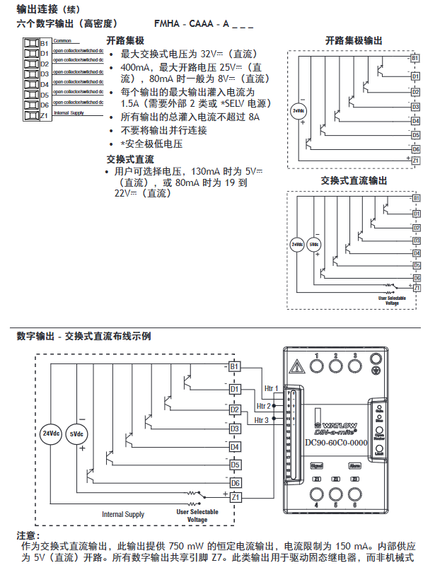
Power controller connection defects (such as DIN-A-MITE and F4T signal interruption, unable to turn off the load);
The control algorithm is set to "on-off" and the hysteresis is too large (causing the heating to not stop in time).
Troubleshooting and resolution steps:
Check the output function settings:
Front panel: Menu → Settings → Output → Select the corresponding output channel, confirm that the "Function Type" is "Heating" (not "Cooling");
If there is an error, modify it to the correct type and restart the controller to take effect;
Verify sensor wiring:
Thermocouple: Disconnect the wiring, confirm that the red wire (negative electrode) is connected to the S terminal, the positive electrode is connected to the R terminal, and if the wiring is reversed, reconnect it;
RTD: 3 wire type needs to confirm S1 (white wire) connected to R1, T1 connected to S2, lead resistance ≤ 10 Ω (measured with an ohmmeter);
Check the output wiring and load:
After the power is cut off, use a multimeter to check the on/off switch of the heater wiring. If there is a short circuit, replace the heater;
Check SSR/relay output: output 100% power to the controller, measure the output terminal voltage (such as 240Vac), and the voltage should disappear after power failure. If there is continuous voltage, replace the SSR/relay;
Verify power controller connection:
If using a DIN-A-MITE power controller, check the signal lines between F4T and DIN-A-MITE (such as switched DC output) to ensure that there is no looseness/disconnection and that the signal can trigger DIN-A-MITE shutdown normally;
Adjust control algorithm:
If it is "on-off" control: menu → control → algorithm → change to "PID", execute automatic tuning (TRU-TUNE) ®+), Reduce overshoot;
If PID overshoot occurs: adjust the proportional band (increase) or integral time (extend) to reduce response speed;
Test validation:
Power on again, set the target temperature (such as 100 ℃), observe whether the process value stabilizes within the set point ± accuracy range (such as ± 1 ℃), and if it still loses control, troubleshoot the controller output hardware (such as replacing the output module).

- ABB
- General Electric
- EMERSON
- Honeywell
- HIMA
- ALSTOM
- Rolls-Royce
- MOTOROLA
- Rockwell
- Siemens
- Woodward
- YOKOGAWA
- FOXBORO
- KOLLMORGEN
- MOOG
- KB
- YAMAHA
- BENDER
- TEKTRONIX
- Westinghouse
- AMAT
- AB
- XYCOM
- Yaskawa
- B&R
- Schneider
- Kongsberg
- NI
- WATLOW
- ProSoft
- SEW
- ADVANCED
- Reliance
- TRICONEX
- METSO
- MAN
- Advantest
- STUDER
- KONGSBERG
- DANAHER MOTION
- Bently
- Galil
- EATON
- MOLEX
- DEIF
- B&W
- ZYGO
- Aerotech
- DANFOSS
- Beijer
- Moxa
- Rexroth
- Johnson
- WAGO
- TOSHIBA
- BMCM
- SMC
- HITACHI
- HIRSCHMANN
- Application field
- XP POWER
- CTI
- TRICON
- STOBER
- Thinklogical
- Horner Automation
- Meggitt
- Fanuc
- Baldor
- SHINKAWA
- Other Brands


