
YOKOGAWA STARDOM FCN-100/FCJ Migration Technology
YOKOGAWA STARDOM FCN-100/FCJ Migration Technology
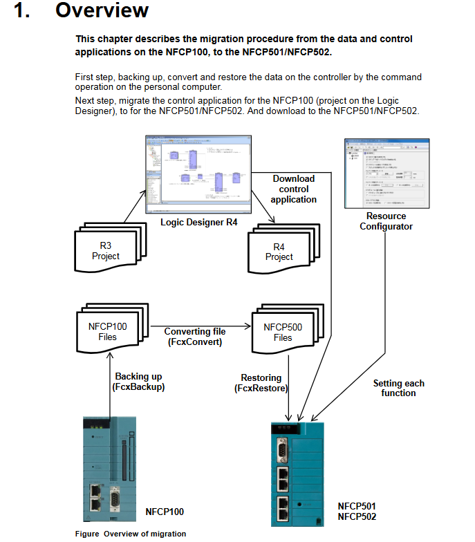
Migration core principles and limitations
(1) Core migration logic
The essence of migration is the process of "adaptation transformation deployment" of source device configuration and application:
Data level: Backup the configuration data (resource configuration, system files) of NFCP100/NFJT100, convert it to NFCP500 compatible format, and then restore it to the target device;
Application level: Upgrade the control projects (R1-R4 versions) in Logic Designer, adapt them to PLC/processor types, recompile and download them to the target device;
Special configuration: Field bus definition and Duolet application need to be separately adapted to the hardware interface and system file format of the target device.
(2) Key Limitations and Rules
Data compatibility:
The FcxConvert command only supports NFCP100 backup file conversion, NFJT100 backup files cannot be converted, and I/O definitions and DUONUS.PRP files need to be reset;
When expanding the hold data area, the hold data saved by NFCP100 cannot be used for NFCP500 and needs to be reconfigured;
Control applications, launch projects, and source files that do not participate in FcxConvert conversion need to be compiled and downloaded separately through Logic Designer.
License restriction: The source device license cannot be migrated to FCN-500, and the CPU module of the target device must be pre bundled with the required license.
IP address inheritance: When restoring converted data, the target device's IP address will automatically inherit the source device's IP address. If modification is required, it needs to be adjusted through the Resource Configurator after recovery.
Hardware interface adaptation: The COM2 port of FCJ needs to be migrated to the RS-232C communication module, and the port name in the application needs to be changed from "COM2" to the module configuration name (such as "RS02").
Detailed explanation of core migration tools and commands
(1) Command line tool functions and usage
Complete syntax and key instructions for the core functions of tool commands
FcxBackup backup source device (NFCP100/NFJT100) data FcxBackup - all - u<username>- p<password><hostname/IP>1. The "- all" parameter requires R3.10+version, and the "- u/- p" parameter requires R4.10+version;
2. Generate a "BACKUP" folder containing data files, resource configuration, DUONUS.PRP, etc;
3. Example: FcxBackup all - u user01- p abc123 192.168.0.1
FcxConvert converts NFCP100 backup files to the target device format FcxConvert.exe - t<NFCP501/NFCP502>- i<source folder>- o<target folder>1. The source folder defaults to "ACKUP", and the target folder needs to be customized (such as "ACKUP_CFCP501");
2. After conversion, the target folder needs to be renamed as "ACKUP" before it can be used for recovery;
3. Example: FcxConvert.exe - t NFCP501- i BackUP - o BackUP_CFCP501
FcxRestore restores the converted data to the target device FcxRestore<hostname/IP>1. Before restoring, it is necessary to clear the hold data in the SRAM of the target device (in conjunction with FcxSaveRetain-c);
2. Example: FcxRestore 192.168.0.1
FcxSaveRetain saves/clears hold data FcxSaveRetain-c<hostname/IP>1. Only use the "- c" parameter during migration (clear SRAM hold data);
2. Ensure that the backup data is correctly mapped to the target device SRAM;
3. Example: FcxSaveRetain - c 192.168.0.1
(2) Tool acquisition and directory structure
Acquisition steps:
Insert R4.20+version system DVD ROM;
Select "DVD Contents" and double-click on "FCN/FCJ Basic Software Package" (FCN-500 corresponds to Pkg.NFCP500. exe in the Pkg.NFCP500 folder);
Specify the installation folder (such as "C: temp"), extract it, and generate the tool files.
Typical directory structure:
plaintext
C:temp
⊙ - NFCP500 # Core Tools Folder
│∝ - FcxBackup.exe # Backup Command
│∝ - FcxConvert.exe # Conversion Command
│└ - FcxRestore.exe # Restore Command
└ - FCXTOOL # Auxiliary Tools Folder
∝ - FcxSaveRetain.bat # Keep Data Processing Batch Processing
└ - save_record. txt # Configuration file
Control the core rules for application migration
(1) PLC type matches processor type
PLC type processor type migration operation (without expanding the hold data area) migration operation (expanding the hold data area) applicable scenarios
IPC40 FCX/FCX_A can be directly recompiled without modifying the project reconstruction resources (PLC=IPC40, processor=FCX_B/FCX_C)+compiling the original configuration of NFCP100, which needs to be expanded to maintain data
IPC32/IPC33- Rebuilding Resources (PLC changed to IPC40)+Copying Configuration (tasks/variables/labels, etc.)+Compiling Rebuilding Resources (PLC=IPC40, processor=FCX_B)+Copying Configuration+Compiling Low Version PLC Type Adaptation Target Device
SH_40- Rebuilding Resources (PLC changed to IPC_40)+Compilation - SH_40 Type Compatibility Upgrade
(2) Processor type description
Processor type applicable to device core characteristics
FCX NFJT100/NFCP100 does not support modules such as NFLF111/NFGS813
FCX_A NFCP100 supports modules such as NFLF111/NFGS813
FCX_B NFCP501/NFCP502 Extended version of FCX_A for maintaining data area
FCX_C NFCP501/NFCP502 supports 3 or more expansion units+NFLF111 and other modules, with device label expansion versions
(3) Project upgrade and compilation
Version compatibility: R1-R3 version projects are automatically converted to R4 format when opened with Logic Designer R4, and cannot be backward compatible with lower version tools after conversion;
Key points of resource reconstruction:
Copy the task definition, global variable definition, device label variable definition, software wiring definition, etc. of the original project;
Configure target device parameters (such as IP address, communication port);
If using a user library, you need to copy the. mwt file and the folder with the same name to "C: YOKOGAWA FCN-FCJ LogicDesigner Libraries", compile and register it;
Download requirements: Perform offline downloads (including controlling applications, launching projects, source files), ensuring that the target device is in online mode.
Detailed process of two migration modes
(1) Mode 1: migrate directly to the target device (complete the whole process on site)
Applicable scenarios: on-site downtime allowed, no need for prior verification, no complex field bus configuration
Core steps (10 steps)
Key precautions for step-by-step operation content
A1 obtains the installation folder of the conversion tool without spaces, and after decompression, confirms the integrity of the tool
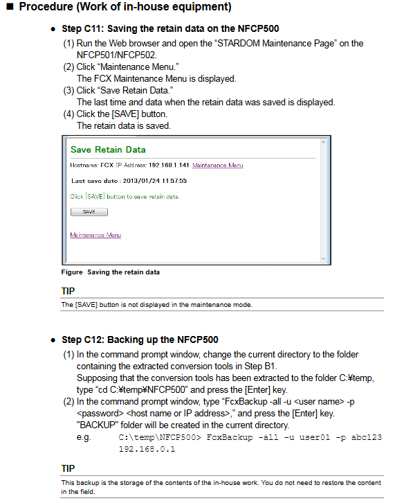
A2 Save NFCP100 Keep Data Login STARDOM Maintenance Page → Maintenance Menu → Save Retain Data → Click [SAVE]; No [SAVE] button in maintenance mode
Switch the command line of A3 backup NFCP100 data to the tool directory, execute the FcxBackup command, and generate the "ACKUP" folder
A4 Convert backup file (NFJT100 skip) Execute the FcxConvert command, rename the destination folder to "ACKUP"
Replace the CPU module with A5, remove the NFCP100, and transfer the Ethernet/RS-232-C cable (connect the Ethernet to the original 1/2 port); The new NFCP500 requires setting the IP address through the Resource Configurator first
A6 target device switches to maintenance mode, logs in to Maintenance Page → Reboot → Reboot (Maintenance Mode) → Confirm startup mode
To restore data to NFCP500, first execute FcxSaveRetain-c to clear and hold the data, and then execute the FcxRestore command; Switch to online mode after recovery
A8 configuration NFCP500 exclusive features can be set through the Resource Configurator: Duolet function, CPU dual machine hot standby, NFCP502 3/4 Ethernet port, SD card, SNTP server, NFJT100 migration I/O definition
A9 Download Control Application Logic Designer R4 Open Project → Compile → Offline Download to Target Device
A10 executes APC (dual machine hot standby scenario) by inserting the standby side CPU module (of the same model and software version) → the resource configurator starts APC (manually executed when automatic start is disabled)
(2) Mode 2: Pre migration verification of internal equipment+on-site replacement
Applicable scenarios: sensitive on-site downtime, complex configuration (including field bus/Duolet applications), and the need to troubleshoot issues in advance
Core process (divided into three stages)
Stage 1: On site preparation (3 steps)
Step operation content output
B1 requires R4.20+tools to be installed on both the on-site and internal engineering PCs for obtaining conversion tools
B2 Save NFCP100 Keep data in the same mode Step A2 Keep data file
B3 backup NFCP100 data in the same mode, A3 step "Backup" folder
Stage 2: Internal device verification (7 steps)
Key points for verifying the operation content of steps
B4 Convert backup files (NFJT100 skip) in the same mode. A4 Step: Convert the "BackUP" folder after the conversion
B5 Configure internal NFCP500 new device with IP, switch to maintenance mode device ready (maintenance mode)
B6 restores data to internal NFCP500 in the same mode. A7 steps successfully restore data without any errors
B7 configuration exclusive functions in the same mode, A8 step function configuration takes effect
B8 download control application in the same mode. A9 steps: successful application download
B9 Verification Function Hardware (Communication, Dual Machine Hot Standby), Control Application Running Normal Verification Report
B10 optional: Backup internal NFCP500 data by executing the FcxBackup command, archive the verified configuration, and internally verify the backup file
Stage 3: On site replacement (steps 4-6)
Scenario step operation content
Internal and on-site I/O configurations are different B11-B16 B11: replace CPU module; B12: Switch maintenance mode; B13: Data recovery; B14: Configure exclusive functions; B15: Download applications; B16: Execute APC (dual machine)
Internal and on-site I/O configurations are the same C11-C14 C11: Save internal NFCP500 to maintain data; C12: Backup internal device data; C13: Replace CPU module; C14: Execute APC (dual machine)
Special Configuration Migration Adaptation
(1) Field bus definition migration (NFLF111/NFLP121/NFLC121 modules)
Core logic: The field bus definition is bound to the engineering PC and needs to be migrated from the source device engineering PC to the target device engineering PC
operating steps
File preparation: Copy the configuration file from the source PC (FOUNDATION field bus: CF/DD file; PROFIBUS: GSD file; CANopen: EDS file);
Define migration:
Same PC upgrade: No need to export/import, definition information is already stored on the PC;
New PC project: Source PC → Resource Configurator export definition → New PC import definition → Download to target device;
Special adaptation: When using FF engineering tools before R2.20, it is necessary to first convert them to FF Configurator format (refer to TI 34P02Q55-01E).
(2) Duolet (Java) application migration
1. System file editing
In the converted DUONUS.PRP file, a "#" comment will be added before JavaStart and AdditionalClassPath. After recovery, the "#" should be removed to activate the application;
Editor's reference: "B 2.4.2 Editing System Setting Files" in IM 34P02Q01-01E.
2. Project migration
Step operation content
1. Rename CallJavac.bat in the project folder to CallJavac.bat.old, and Ftp2Fcx.bat to Ftp2Fcx.bat.old
Copy CallJavac.bat, CallJavac_Fcn500.bat, and Ftp2Fcx.bat from the "Project Template" directory of the tool installation directory to the project folder
3. Edit Ftp2Fcx.bat, configure the target device IP, package name included in the JAR package, and JAR file name
Execute CallJavac.bat or CallJavac_Fcn500.bat to confirm the generation of the Duolet application
5. Note: The deprecated method of IEC control data access class cannot be used for FCN-500
- OMRON
- ABB
- General Electric
- EMERSON
- Honeywell
- HIMA
- ALSTOM
- Rolls-Royce
- MOTOROLA
- Rockwell
- Siemens
- Woodward
- YOKOGAWA
- FOXBORO
- KOLLMORGEN
- MOOG
- KB
- YAMAHA
- BENDER
- TEKTRONIX
- Westinghouse
- AMAT
- AB
- XYCOM
- Yaskawa
- B&R
- Schneider
- KONGSBERG
- NI
- WATLOW
- ProSoft
- SEW
- ADVANCED
- Reliance
- TRICONEX
- METSO
- MAN
- Advantest
- STUDER
- DANAHER MOTION
- Bently
- Galil
- EATON
- MOLEX
- DEIF
- B&W
- ZYGO
- Aerotech
- DANFOSS
- Beijer
- Moxa
- Rexroth
- Johnson
- WAGO
- TOSHIBA
- BMCM
- SMC
- HITACHI
- HIRSCHMANN
- Application field
- XP POWER
- CTI
- TRICON
- STOBER
- Thinklogical
- Horner Automation
- Meggitt
- Fanuc
- Baldor
- SHINKAWA
- Other Brands
- UniOP
- KUKA
- Iba
- Beckhoff
-
 Basler D90 96801 100 PCB Card
 -
 Basler XR2002F Voltage Regulator (110 VAC, 48-480 Hz)
 -
 Basler SR8A-2B14B3A Regulator
 -
 Basler 9561500100 Module
 -
 Basler DECS-400 BE1-11 System
 -
 Basler DECS-100-B15 Excitation Control
 -
 Basler SCP 210 Frequency Controller
 -
 Basler SR4A-2B15B3A Static Voltage Regulator
 -
 Basler BE1-32R Power Relay
 -
 Basler PIA2400-17GM Power Interface Adapter
 -
 Basler MVC 232 Manual Voltage Control Module
 -
 Basler SSR 32-12 Static Voltage Regulator
 -
 Basler 5MW AVR Generator Voltage Regulator
 -
 Basler VR63-4B Voltage Regulator
 -
 Basler DECS-100-A05 AVR for Engine Generator
 -
 Basler DECS-100-B15 Automatic Voltage Regulator
 -
 Basler BE1-32R Directional Power Relay
 -
 Basler BE1-87B Differential Relay
 -
 Basler UFOV 260A Protective Module
 -
 Basler 9-2614-02-100 PCB Rev M
 -
Basler DECS-100-B15 Digital AVR
-
 Basler 9284900103 PS DECS-400N
 -
 Basler D4N3H1U Intertie Protection
 -
 Basler DECS-100-B15 A15 AVR
 -
 Basler KR4F Voltage Regulator
 -
 Basler BE26434 T14 Transformer
 -
 Basler SR8A-2B15B3A Regulator
 -
 Westinghouse 774B472A12 AR Relay
 -
Basler DECS-100-B15 AVR
-
Basler XR2002F Regulator 110V
-
Basler SR125-E Static Regulator
-
 Basler SSR 125-12 Regulator
 -
 Basler MOC2599 Motor Pot
 -
 Basler BE1-DFPR Feeder Relay
 -
 Basler CBS 305 Current Boost
 -
 Basler BE1-25 AutoSync
 -
 Basler MVC 300 Voltage Control
 -
 Basler BE3-25A AutoSync
 -
 Basler KR7FF Static Regulator
 -
 Basler 90-49000-100 Regulator
 -
 Basler 880 kVA Dry Type Transformer Specs
 -
 Basler Electric BE1-25 Sync-Check Relay Specs
 -
 Basler SSR 125-12 Voltage Regulator Specs
 -
 Basler Electric BE1-851 Overcurrent Relay Review
 -
Basler Electric 149D930G02 Control Sub-Assembly
-
 Basler Electric BE1-81O/UT Frequency Relay Specs
 -
 Basler Electric BE1-51/27C Overcurrent Relay
 -
 Basler Electric 149D956G02 Industrial Component
 -
Basler Electric BE1-51A Overcurrent Relay Specs
-
 Basler Electric BE1-40Q Loss of Excitation Relay
 -
 Basler DECS-200 Excitation Control System
 -
 Basler DECS-200 Voltage Regulator 56-277V AC / 125V DC
 -
Basler BE1-87T Transformer Differential Relay
-
 Basler RDP-110-S1 Protection Relay
 -
 Basler BE1-700V Digital Protective Relay
 -
 Basler BE1-951 Overcurrent Protection System
 -
 Basler DECS-300 Digital Excitation Control
 -
 Basler DECS-200 Digital Excitation Control
 -
 Basler DECS-200-1C Excitation Control System
 -
Basler DECS-200-1L Digital Excitation Control
-
 Basler Electric BE1-GPS Generator Protection System
 -
Basler Electric DECS-200-1C Digital Excitation Controller
-
 Basler Electric DECS125-15 Excitation Control with Power Module
 -
 Basler Electric BE1-87G Differential Relay
 -
 Basler Electric BE1-11 Protection System I5A3M2P2N0EA00
 -
Basler Electric DECS-200-1C Excitation Control System
-
Basler Electric BE1-11g Generator Protection Relay
-
Basler Electric DECS 125-15-B2C1 V2.0.9 Excitation Control
-
 Basler Electric BE1-81O/UT3ED1JA7N2F Frequency Relay
 -
Basler Electric BE1-81O/UT3EE1YB7N1F Frequency Relay
-
 Basler Electric DECS-200-1L Digital Excitation Control System
 -
Basler DECS125-15-B2C1 Excitation Control
-
 Basler 9507900205 SSR Retrofit Voltage Regulator
 -
 Basler BE2000E Digital Voltage Regulator
 -
 Basler BE1-GPS Generator Protection System
 -
Basler DECS-250-CN1CN1N Digital Excitation Control
-
 Basler DGC-2020 Genset Controller
 -
 Basler BE1-81O UT3ED1LA7N0F Frequency Relay (Variant)
 -
 Basler BE1-81O UT3EE1YA9S0F Frequency Relay (Variant)
 -
Basler BE1-81O Over/Under Frequency Relay
-
Basler DECS125-15 Digital Excitation Control
-
Basler Electric BE1-951 Overcurrent Protection System
-
 Basler Electric BE1-700V Digital Protective Relay
 -
 Basler Electric APR63-5 Automatic Voltage Regulator
 -
Basler Electric BE1-851 Overcurrent Protection System
-
Basler Electric DECS-250-LN1SN1N Excitation Control
-
 Basler Electric BE1-87T Transformer Differential Relay
 -
Basler Electric DECS-200-1L Excitation Control System
-
 Basler Electric 9310300100 DECS-300 Excitation Control
 -
 Basler Electric SSE-N 125-4.5KW Shunt Exciter Regulator
 -
 Basler Electric DGC-2020HD-5NS1DNSBA Genset Controller
 -
Basler Electric BE1-81-O/UT3EE1JB7N1F Frequency Relay
-
Basler Electric BE1-81T1EE1WA0N1F Frequency Relay
-
 Basler Electric BE1-25M1EA6PN5R1F Sync-Check Relay
 -
 Basler Electric BE1-GPS Generator Protection System
 -
Basler Electric DECS-250-LN1SN1N Excitation Control Rev V
-
 Basler Electric DECS-250-CN2CN1N Excitation Control
 -
Basler Electric BE1-50/51B-207 Overcurrent Relay
-
Basler Electric DECS-300-C0N0 Excitation Control System
-
Basler Electric DECS-200 Digital Excitation Control System
-
Basler Electric DECS-250-LN1CN1N Excitation Unit
-
Basler Electric DECS-250 LN2SA1D Excitation Unit Specs
-
Basler Electric BE1-87T Transformer Relay Review
-
Basler Electric BE1-11 Protection System
-
Basler Electric BE1-GPS100-E4N1H1N Protection System
-
 Allen-Bradley 442G-MABH-R Safety Module
 -
 Beckhoff CX1030-0111 PLC Assembly Profile
 -
 FANUC IC693CPU364 PLC Module
 -
 Orange Denmark Type 200816 220 PLC Specs
 -
 OMRON C200H-SNT31 Sysmac PLC Module
 -
 Allen Bradley 20AB022A3AYNANC0 PowerFlex 70
 -
 OMRON C200HW-PCU01 Position Control Unit
 -
 ABB AO845A-eA Analog Output Module
 -
 OMRON CJ1M-CPU22 CPU Unit
 -
 Allen Bradley 100-E265ED11 Contactor
 -
 Honeywell 51304511-100 Interface Module
 -
 SOLEXY BXF3S0101N0018 Gateway Module
 -
 OMRON CJ2H-CPU65 CPU Unit
 -
 Automation Direct GS2-45P0 AC Drive
 -
 M68-2000 2-Axis Motion CNC Controller
 -
 OMRON CJ1M-CPU11 V3.0 PLC CPU Unit
 -
 OMRON CJ1W-NC413 4-Axis Positioning Controller
 -
 OMRON 3G2A3-PRO16 Programming Console HMI
 -
 Siemens 3VT8440-2AA04-2GA2 Molded Case Circuit Breaker
 -
 Siemens 3RT5045 Contactor Series
 -
 OMRON C200HS-CPU01-E SYSMAC PLC Controller
 -
 OMRON C500-NC103-E Positioning Control Unit
 -
 OMRON CJ1W-TC001 Temperature Control Unit


