
Foxboro ™ DCS Field Device Controller 280(FDC280)
Foxboro ™ DCS Field Device Controller 280(FDC280)
Product Overview and Core Positioning
FDC280 is a distributed and optional fault-tolerant on-site installation controller, with the core function of implementing Foxboro ™ The integration of DCS and field devices does not require additional fieldbus modules (FBM), and it also undertakes process control and alarm tasks. It is mainly positioned as the "field device integration center", which is different from the same type of FCP280 (which does not support PIO bus and focuses on Ethernet/serial protocol integration).
1. Core functions
Device integration: Directly interface with Ethernet/serial field devices that support multiple protocols, collect device data for display, historical storage, and execute control tasks.
Control capability: Built in adjustment control, logic control, timing control, sequence control functions, supporting alarm detection and notification.
Hardware architecture: Adopting dual core ARM ® SOC processor with clear dual core division of labor:
Core 1 (Control Core): Run control software and DCS control network communication software, supporting fault-tolerant operations.
Core 2 (I/O core): Run device integration software, independently handle on-site device connections and status diagnostics.
Basic requirements: A host workstation with Foxboro DCS Control Core Services v9.3 or higher must be installed, and connected to the control network via 100Mbps fiber/copper Ethernet. It must have obtained ISASecure EDSA Level 1 security certification.
2. Key difference: FDC280 vs FCP280
Comparison item FDC280 FCP280
Core positioning on-site equipment integration (Ethernet/serial port) universal process control
PIO bus support not supported
Core advantage: No FBM required, directly integrated with field devices compatible with traditional PIO bus devices
Network configuration plan
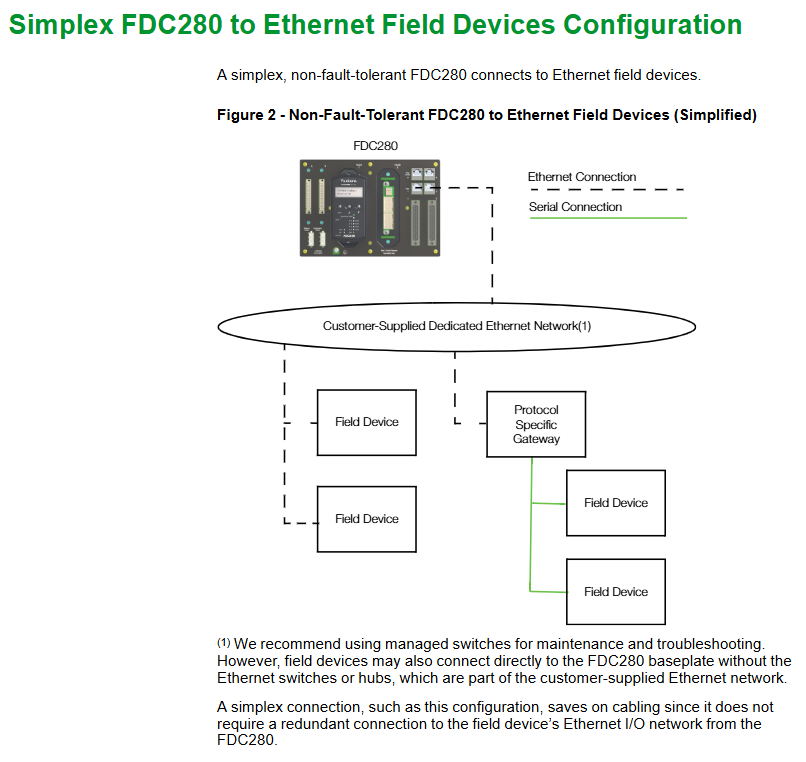
FDC280 supports both Ethernet and serial network configurations, divided into two modes: "simplex" and "fault tolerant", to meet the redundancy requirements of different field devices.
1. Ethernet network configuration
Support direct connection to Ethernet field devices or connection to serial devices through a "protocol specific gateway" (to achieve Ethernet serial bridging), with three core solutions:
Configuration Type Applicable Scenarios Key Features
Simplex, a single FDC280 module for scenarios with low reliability requirements, does not require redundant connections and saves wiring costs
Fault tolerant - Independent network with high reliability requirements, on-site equipment requires independent redundant network dual FDC280 modules (left/right), connected to two independent Ethernet networks provided by customers, with module IP addresses that can be the same or unique
Fault tolerant - Shared network field devices without independent redundancy requirements (such as single port devices). Dual FDC280 modules share one Ethernet network, supporting single port device access and reducing network complexity
Note: It is recommended to use a management switch for easy maintenance and troubleshooting; The device can also be directly connected to the FDC280 motherboard without the need for a switch.
2. Serial port network configuration
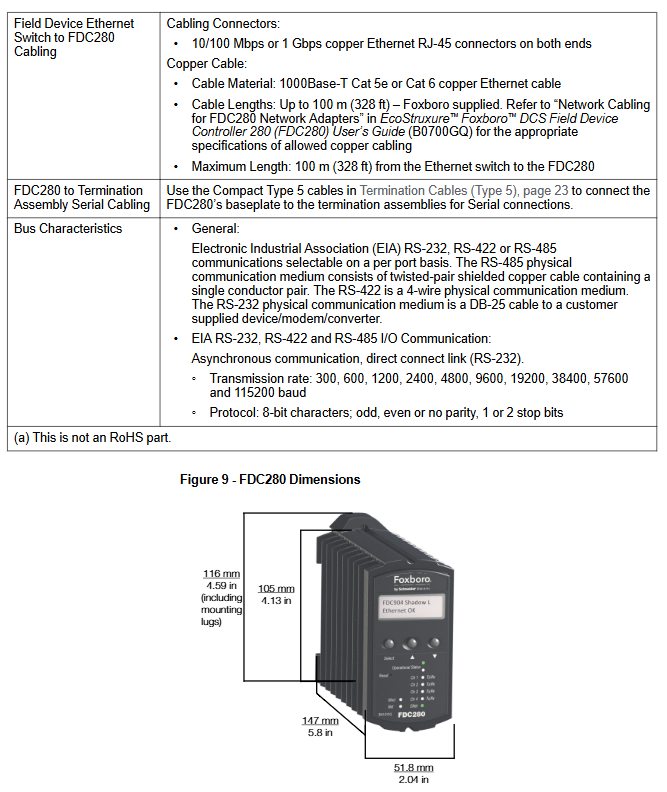
Each module of FDC280 contains 4 independently configurable serial ports (supporting RS232/RS422/RS485), with a maximum support of 128 serial field devices (up to 32 devices per RS485 port). The core solution is divided into 2 types:
Non fault-tolerant (Simplex): A single FDC280 can be connected to a single port serial device through a "Terminal Component (TA)", supporting RS485 multi station connection without a modem and RS232/RS422 direct connection.
Fault tolerant type: Dual FDC280 modules are connected to devices through TA and adapted to different port devices:
Dual port device: The left/right module connects the two ports of the device separately to achieve redundant communication.
Single port device: RS232 needs to be connected to two TAs through a Y-shaped cable; RS485/422 can be directly connected through a dual module TA sharing connection.
Core features and performance parameters
1. Key functional characteristics
Specific description of characteristic categories
The device and I/O capacity support a maximum of 256 field devices, 8000 soft I/O points, and 8252 total functional blocks (including Station blocks, ECB components, etc.). Please refer to the FDC280 sizing tool (B0700GS) to calculate the load
The protocol supports 6 core protocols, some of which support concurrent multi instance/multi version (see table below for details)
The diagnostic capability has a built-in "diagnostic driver" that can capture real-time communication messages with the device and send them to the workstation diagnostic application without physical interruption
Fault tolerance mechanism dual module "marriage" operation, Control Network communication requires dual module messages to be matched bit by bit before sending; Core 1 supports primary/backup switching, while Core 2 supports redundancy state comparison and role handover
In self hosted mode, the control database checkpoint file is stored in flash memory, and the host can autonomously start and execute control policies when offline
Software updates distinguish between "Major updates (new features, no online upgrade support)" and "Minor updates (only module switching, no process interruption)"
Environmental adaptability die-casting aluminum shell, no need for ventilation, supports Class G3 harsh environment (ISA S71.04 standard), CE certification for on-site installation
Time synchronization supports GPS satellite UTC time (external) or DCS internal TimeKeeper synchronization (internal), with data timestamp accuracy of 10 times/second (minimum scanning interval of 100ms)
2. Support protocols and concurrency capabilities
Protocol name, part number, multiple protocols, concurrent support, same protocol, multiple instances support
Modbus TCP Client K0177AH Yes Yes
Modbus RTU&ASCII Client K0177CV Yes
Triconex ™ TSAA Client K0177DE is
OPC UA Client K0177EC (single instance only)
Is EtherNet/IP Scanner Driver K0177EP
PROFINET IO Controller K0177FU No No (single instance only)
3. Functional specification parameters
Specific numerical values for parameter categories
The maximum execution speed of functional blocks with a processor performance of 16000 blocks per second, and the minimum block processing cycle (BPC) of 100ms
The maximum capacity of a single sequence block is 32KB
IPC connects 200 data source points (providing external data), 30 sink points (receiving external data), and 1 dedicated internal point
OM (Object Manager) can scan a database with a maximum capacity of 28000 points (18000 points when BPC ≥ 200ms, 7500 points when BPC=100ms); The maximum convergence point is 11250 points
Configurable block period of 0.1/0.2/0.5/0.6/1/2/5/6/10/30 seconds, 1/10/60 minutes
Fault tolerant module pairing time is less than 0.5 seconds
Hardware and environmental specifications
1. Core hardware components and parameters
The FDC280 hardware includes four categories: "module", "motherboard", "network adapter", and "terminal component". The key parameters are as follows:
Component type, model/part number, key specifications
FDC280 module RH101FQ size: height 105/116mm (including installation ears) x width 51.8mm x depth 147mm; single module weight 0.8kg
The base plate RH101KF (2 bits) supports 1 non fault tolerant module or 2 fault tolerant modules, including 2 10/100Mbps/1Gbps copper cable Ethernet RJ45 interfaces, 2 37 pin D-type serial port interfaces, and 2 time synchronization interfaces
Network adapter fiber optic: RH924WA (Rev. E+); Copper cable: RH924UQ (Rev. D+) takes power from the base plate, fiber supports multimode 62.5/125 μ m cable (maximum 2km), copper cable supports Cat5 (maximum 100m)
Serial terminal component ring terminal post: P0926PA; Tightening screws: RH926GH weighs 363g and 272g respectively, and needs to be paired with Type 5 terminal cables (such as RH100HV-1m and RH100HZ-5m)
2. Power and environmental requirements
Category specifications
Power requirement input voltage: 24VDC (redundant,+5%/-10%); The maximum power consumption of a single module is 8.5W
Working temperature -20~60 ℃ (-4~140 ℉)
Storage temperature -40~70 ℃ (-40~158 ℉)
Relative humidity 5%~95% (no condensation)
Altitude operation: up to 3000m; storage: -300~12000m
Anti pollution level Class G3 (ISA S71.04), supports 10-year mixed gas exposure testing (EIA 364-65A Class III), module with conformal coating (conformal coating: protective coating)
Vibration resistance 0.5g (5~500Hz)
3. Compliance certification
Electromagnetic Compatibility (EMC): Compliant with Directive 2014/30/EU, EN 61326-1 Class A (Emission and Industrial Immunity).
Product safety: UL/UL-C certification (applicable to Class I, Groups A-D, Zone 2), EU Low Voltage Directive (2014/35/EU), ATEX Directive (2014/34/EU, DEMKO Ex nA IIC T4 Gc, applicable to Zone 2).
Environmental compliance: Compliant with the EU RoHS Directive (2011/65/EU and revised versions 2015/863, 2017/2102).
California Proposition 65: Products containing lead and lead compounds may cause cancer or reproductive harm, details can be found at www.P65Warning.ca.gov.
Fault tolerance mechanism and reliability design
The "fault-tolerant" core of FDC280 consists of dual module redundancy, independent diagnosis, and seamless switching, covering the control network, CPU, and I/O levels to ensure uninterrupted processes
1. Three layer fault-tolerant/redundant design
Level fault tolerance/redundancy mechanism switching logic
The dual modules of the control network are connected through the backplane and share control network access (dual switches). Communication messages need to be matched bit by bit by the dual modules before being sent. When a fault is detected, the non faulty module takes over control without process interruption
Core 1 (control core) primary/backup mode, real-time synchronization status. When the primary core fails, the backup core immediately switches to primary dynamic mode
Core 2 (I/O core) independently diagnoses the connection status of dual core devices. When the main core fails and the backup core device is better connected compared to the backup core status, the main core resets and hands over the role
The main module on the I/O side is responsible for reading and writing I/O points, while the backup module monitors device connections through "heartbeat commands" and synchronizes I/O values in real-time. When the main module loses connection, the backup module seamlessly takes over without any process fluctuations
2. Maintain convenience
Hot plug support: Replacing the FDC280 module does not require disconnecting the backplane power supply, and does not affect the field I/O signal of another module.
Status visualization: The front of the module includes an LCD display screen (displaying module identification, role, hardware version, network status) and LED indicator lights (running status, Ethernet connection status), supporting the configuration of "letterbug" through panel buttons.
Summary
FDC280 is Schneider Foxboro ™ DCS is a specialized controller designed for the "field equipment integration" scenario, with the core advantages of not requiring FBM to directly interface with multi protocol devices, supporting fault-tolerant redundancy, and adapting to harsh field environments. It is suitable for industries such as chemical, power, oil and gas that require high reliability field control. Its dual core architecture, flexible network configuration, and three-layer fault-tolerant design can effectively reduce the complexity of on-site wiring, improve the integration efficiency and system availability between DCS and on-site devices.
- OMRON
- ABB
- General Electric
- EMERSON
- Honeywell
- HIMA
- ALSTOM
- Rolls-Royce
- MOTOROLA
- Rockwell
- Siemens
- Woodward
- YOKOGAWA
- FOXBORO
- KOLLMORGEN
- MOOG
- KB
- YAMAHA
- BENDER
- TEKTRONIX
- Westinghouse
- AMAT
- AB
- XYCOM
- Yaskawa
- B&R
- Schneider
- KONGSBERG
- NI
- WATLOW
- ProSoft
- SEW
- ADVANCED
- Reliance
- TRICONEX
- METSO
- MAN
- Advantest
- STUDER
- DANAHER MOTION
- Bently
- Galil
- EATON
- MOLEX
- DEIF
- B&W
- ZYGO
- Aerotech
- DANFOSS
- Beijer
- Moxa
- Rexroth
- Johnson
- WAGO
- TOSHIBA
- BMCM
- SMC
- HITACHI
- HIRSCHMANN
- Application field
- XP POWER
- CTI
- TRICON
- STOBER
- Thinklogical
- Horner Automation
- Meggitt
- Fanuc
- Baldor
- SHINKAWA
- Other Brands
- UniOP
- KUKA
- Iba
- Beckhoff
-
 Basler XR2002F Voltage Regulator 9139400101
 -
 Basler 2D80367G23 DXCB De-Excitation Module 1200V 5000A
 -
 Basler SR4A-2B15B3A Static Regulator 120V 50/60Hz
 -
 Basler SSR 125-12NF Static Regulator 9 1859 00 106
 -
 Basler BE1-BPR Breaker Protection Relay 9272000315
 -
 Basler SSR 63-12 Static Regulator 9 1859 00 101
 -
 Basler AEM-2020 Analog Expansion Module
 -
 Basler BE 25231-001 Transformer BE25231001
 -
 Basler MVC 108 Manual Voltage Control 9037000102
 -
 Basler PSS-100-Y5 Power System Stabilizer 0.1-5.0Hz
 -
 Basler Electric BE1A-25-M1G-A6T-N4V1F Sync-Check Relay
 -
 Basler Electric SR8A2B10B1A Static Voltage Regulator
 -
Basler Electric SR8A2B10B1A Static Voltage Regulator
-
Basler Electric SSR 125-12 Static Voltage Regulator 9185900102
-
 Basler Electric 90-73900-102 Power Supply (Westinghouse 2374A07G03)
 -
 Basler Electric 9400200117 Control Power Unit 12/24VDC 20W
 -
Basler Electric BE1-87G Solid State Generator Differential Relay
-
 Basler Electric BE1-32R Style C3ED1TA0S1F Solid State Protective Relay
 -
Basler Electric SR32A2B05B3E Static Voltage Regulator
-
 Basler Electric SR8A2B06B3A Static Voltage Regulator
 -
Basler MOC3502 90-72300-116 Motor Potentiometer
-
 Basler SR4A2310B1A Static Voltage Regulator
 -
 Basler Electric 90-88800-102 PRS-250 Veri-Sync Relay
 -
Basler Electric 90-88800-102 PRS-250 Veri-Sync Relay
-
Basler SR4A-2B05A3E Static Regulator SR4A2B05A3E
-
 Basler 9-0723-00-130 9072300130 Control Module
 -
 Basler BE1-79MA10A6JC0L0F Reclosing Relay
 -
 Basler CBS-377 Current Boost System 91096001
 -
Basler SR4A1B05A3A Static Regulator 480V 62.5V 10VA
-
 Basler BE159N A7ED1JC0S0F Protective Relay BE159N-0
 -
 Basler BE3-25A Auto-Synchronizer S.No. 728
 -
 Basler BE1-50 Instantaneous Overcurrent Relay G4EA1RG0N0F
 -
 Basler Electric KT3B Voltage Regulator
 -
 Basler Electric ACA2500-14GCSYM GigE Camera
 -
 Basler Electric XR2002F Voltage Regulator
 -
 Basler Electric BE1-50 Instantaneous Overcurrent Relay F2EA1PA0N5F
 -
 Basler Electric CBS 212A Current Boost System
 -
Basler Electric BE147NE3FE1PC3N3F Negative Sequence Voltage Relay
-
 Basler Electric BE1-79MA10A6JC0L0F Automatic Reclosing Relay
 -
Basler Electric BE1-59N A6E E1C B0N1F Neutral Overvoltage Relay
-
 Basler Electric MVC 108 Manual Voltage Control
 -
 Basler Electric BE1-59-A4E-E1C-A0N0F Overvoltage Relay
 -
Basler BE1-57/27R Solid State Protective Relay
-
 Basler BE3-25AX Time Overcurrent Relay
 -
BASLER ELECTRIC BE1-24/A1EF1JC1N0F / BE124A1EF1JC1N0F Overvoltage Relay
-
Basler Electric Solid State Protective Relay BE1-32R Style B2ED1PB0N0F
-
Basler BE3-51-3E1E1 9320000110 24VDC Overcurrent Relay
-
 Basler UFOV 260A Underfrequency Overvoltage Module
 -
 Basler 50F4EA1PA0N0F Instantaneous Overcurrent Relay
 -
Basler BE1-50 Instantaneous Overcurrent Relay
-
 Basler BE1-32 Solid State Protective Relay
 -
Basler SCP 250-G-60 VAR Power Factor Controller
-
Basler BE1-59N A5EE1KC0N0F Ground Fault Relay
-
Basler BE1-79A Reclosing Relay
-
Basler BE1-32R E1EA1OA0N0F Reverse Power Relay
-
 Basler DCQA-103 DCQC104-1 CMX-7D Circuit Board
 -
 Basler SSR125-12 Static Regulator 918500102
 -
Basler 90 17709 112 Regulator Control Board
-
 Basler AVC63-4 AVC634 Voltage Regulator
 -
 Basler 9 1049 04 100 PC Board Control Module
 -
Basler SR4A-2B03B3A Static Voltage Regulator
-
 Basler SR8A-2B15B3A Static Voltage Regulator
 -
 Basler KR7FFX Static Regulator 840V
 -
 Basler EL200-7 Voltage Regulator 90-660VAC 7A
 -
 Basler PRP210-1 Reverse Power Relay 9056300102
 -
 Basler SSR 63-12 Static Regulator 600VAC
 -
 Basler 9289901106 Digital Board
 -
Basler DECS100 Voltage Regulator DECS100A01
-
Basler Electric CEM-2020 Contact Expansion Module
-
Basler Electric BE3-25-1 C1 N4 Synchronizing Check Relay
-
Basler Electric ACA2000-50GM GigE Camera 2MP 50fps
-
 Basler Electric ACA2240-20GMSYM GigE Camera Sony IMX264
 -
Basler BE1-50G Ground Overcurrent Relay
-
Basler PRS250 Veri-Sync Relay
-
Basler MOC2199 Output Module
-
 Basler UFOV 260A Underfrequency Overvoltage Module
 -
 Basler BE-15482-001 Control Module
 -
Basler LSP4-7 Protective Relay
-
 Basler SCP 250-G-60 VAR Power Factor Controller
 -
Basler BE146N Negative Sequence Overcurrent Relay
-
Basler APR63-5 Automatic Voltage Regulator
-
Basler 9507900107 SR8A Retrofit Voltage Regulator
-
Basler BE1-320 Directional Power Relay
-
 Basler KR7F Voltage Regulator 9116200100
 -
Basler UFOV 260A Overvoltage Protective Module
-
 Basler AEC63-7 Analog Excitation Controller
 -
Basler 9992D90G01 Control Module
-
Basler 6966D22G01 Control Board
-
Basler 6965D40G01 Control Board
-
 Basler BE1-50/51M-104 Overcurrent Relay
 -
Basler BE1-BPR Programmable Breaker Relay
-
 BASLER Electric SSR 125-9 1256 00 102 Static Voltage Regulator
 -
Basler Electric MVC 112 Manual Voltage Control
-
 Basler Electric 9321000102 Control Module
 -
 Basler Electric RA-70-MDCT7 Rectifier Assembly
 -
 Basler Electric ACA1300-60GM GigE Camera
 -
 Basler Electric 6427C85G01 Interface Board
 -
Basler Electric 6965D05G01 Control Board
-
Basler Electric ACA2500-14UC Current Transducer
-
Basler Electric 9170206111 Protective Relay
-
Basler Electric BE1-11-G6D1M1J1P0E000 Protection Relay
-
Basler Electric BE1-50/51B-107 Overcurrent Relay
-
 Basler 9121000106 Voltage Controller
 -
 Basler B3E-E1P-A0N0F Solid State Protective Relay
 -
 Basler 9121000106 Manual Voltage Control
 -
Basler PRP320 Motor Pull-out Relay
-
 Basler SSE-N 250-9KW Shunt Exciter Regulator
 -
 Basler BE1-50-51B-107 Overcurrent Relay
 -
 BASLER ELECTRIC MVC 108 MANUAL VOLTAGE CONTROL MODULE 9 0370 00 102
 -
Basler BE1-59N-A7E-D1J-D0N0F Ground Overvoltage Relay
-
Basler BE1-46N-G1E-B8P-B0N0F Negative Sequence Overcurrent Relay
-
Basler BE1-951 Overcurrent Protection System
-
 Basler Electric MOC2199 Motor Operated Potentiometer
 -
Basler Electric BE1-60 Voltage Balance Solid State Relay B1FA1C1M1F
-
Basler Electric BE1-67N Directional Overcurrent Relay
-
Basler Electric PIA2400-17GM Interface Module
-
 Basler Electric V6RAB Rectifier Module
 -
Basler Electric BE1-32R Reverse Power Relay B2E E1R A0N1F
-
Basler Electric IFM-150 Firing Circuit Chassis 120V AC
-
 Basler Electric IFM-102 Firing Circuit Chassis 120V AC
 -
 Basler Electric 9170206111 NSNP Control Module
 -
Basler Electric SSR 63-12 Static Voltage Regulator
-
 Basler UFOV 260A Overvoltage Protective Module
 -
Basler SCA1300-32GM CCD Camera Lens Enclosure
-
Basler BA1-27 Under Voltage Relay
-
Basler 149D866G06 Control Board
-
 Basler 9072300130 Power Supply Module
 -
Basler CBS 305 Current Boost System


