
YOKOGAWA FG410/FG420 arbitrary waveform editor
Select waveform type and parameters for each page, set "Effect" to "K Effect" to enable the page, and disable "No Effect".
Click "All Page OK" to generate multi page waveforms, and switch between page numbers in the toolbar to view them.
4. Waveform and parameter transmission
Synchronize waveform data and oscillator parameters with FG410/FG420 instrument through the "System Settings Screen". The operation steps are as follows:
Click on "Setup → Setup" to open the system settings screen (including 4 tabs: System/Unit/Waveform/Oscillator).
Basic Settings (System tab):
Select the model (FG410/FG420), interface (USB (TMC)), and instrument serial number (automatically recognizes connected devices).
Axis unit setting (Unit tab):
X-axis: Supports "Address", "Time" (time, linked with oscillator cycle), and "User Unit" (customizable, such as 0~360 °).
Y-axis: Supports "Data" (16 bit data), "Voltage" (voltage, linked with oscillator amplitude), and "User Unit" (customized, such as -1~1).
Waveform memory settings (Waveform tab):
Select the memory number (1~128, 0 is non transferable for editing memory), transfer format ("Array Format" array format, "Control Point Format" control point format, the latter has a smaller data volume).
Click "Transfer Data" to transfer the waveform to the instrument, and "Read Data" to read the waveform from the instrument.
Oscillator settings (Oscillator tab):
Set parameters such as channel (only FG420 supports dual channels), output switch (ON/OFF), frequency/period, amplitude, DC offset, etc.
Click on 'Oscillator Setup' to transfer the parameters to the instrument and ensure that the waveform output meets the requirements.
Attention: FG410/FG420 memory 1-128 is non-volatile, and data will not be lost when power is turned off after transmission; Dual channels need to be transmitted to different memory numbers to avoid waveform coverage.
5. File operation and printing
(1) File format and saving/reading
The software supports 6 file formats to meet the needs of different scenarios:
Characteristics of file type extension usage
Dedicated binary file. wdb saves waveform data, instrument settings, and small axis unit volume, containing complete information that can only be recognized by software
Text data file. txt saves waveform data (1 line, 1 16 bit integer), which can be opened in Notepad/Excel for easy processing by other applications
The waveform function file. wfn saves standard waveform parameters and numerical expressions in text format, which can be edited and re read to generate waveforms
Control point file. prn saves interpolated control points (X/Y data) in text format for reusing interpolated waveform settings
PWF parameter file. pwf saves PWF waveform templates and parameter text formats, allowing for quick access to commonly used PWF settings
The system settings file. ocb saves instrument models, interfaces, axis units, and other binary formats, which are only recognized by software and used for quick recovery of settings
Operation steps: Select the format and path through "File → Save" and "File → Open", and the extension will be automatically added when saving.
(2) Print
Support printing the current waveform (without grid) or setting interface (such as waveform generation parameters, PWF settings), operation steps:
Open the interface to be printed (such as waveform display screen, PWF screen).
Click "File → Print" (Ctrl+P) to set the page margins (top/bottom/left), printer, and font.
Click "OK" to print. Waveform printing only displays the current view range, and the zoom needs to be adjusted in advance.
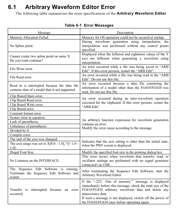
Troubleshooting and Maintenance
1. Common errors and solutions
The possible errors and countermeasures during software operation are as follows:
Solution to Error Information Causes
Memory Allocation Failed. Insufficient memory allocation during startup. Close other applications and restart software; If it occurs frequently, check if the system memory is sufficient
No Spline point interpolation generates waveforms without setting control points. Add at least 2 control points before performing interpolation
File Read/Write error: File read/write failure (e.g. path does not exist, insufficient permissions). Check if the save path exists and run the software with administrator privileges; Damaged files need to be recreated
No listeners on the FACE USB not connected to the instrument or driver not installed. Check the USB connection, reinstall the NI-VISA driver, and restart the instrument and software
Transfer is interrupted. If the instrument malfunctions (such as insufficient memory) and prompts "Out of memory", delete the useless waveforms in the instrument; Otherwise, restart the instrument and retry
Illegal Font Size When printing, adjust the font size in the print settings (if it is set to 12) to avoid exceeding the range
2. Software maintenance
CD maintenance: Store in a cool and dry place, avoid direct sunlight and dust; Wipe with a soft dry cloth when dirty, and prohibit the use of solvents such as benzene; Use a marker pen to write on the label surface to avoid scratches from hard objects.
- OMRON
- ABB
- General Electric
- EMERSON
- Honeywell
- HIMA
- ALSTOM
- Rolls-Royce
- MOTOROLA
- Rockwell
- Siemens
- Woodward
- YOKOGAWA
- FOXBORO
- KOLLMORGEN
- MOOG
- KB
- YAMAHA
- BENDER
- TEKTRONIX
- Westinghouse
- AMAT
- AB
- XYCOM
- Yaskawa
- B&R
- Schneider
- KONGSBERG
- NI
- WATLOW
- ProSoft
- SEW
- ADVANCED
- Reliance
- TRICONEX
- METSO
- MAN
- Advantest
- STUDER
- DANAHER MOTION
- Bently
- Galil
- EATON
- MOLEX
- DEIF
- B&W
- ZYGO
- Aerotech
- DANFOSS
- Beijer
- Moxa
- Rexroth
- Johnson
- WAGO
- TOSHIBA
- BMCM
- SMC
- HITACHI
- HIRSCHMANN
- Application field
- XP POWER
- CTI
- TRICON
- STOBER
- Thinklogical
- Horner Automation
- Meggitt
- Fanuc
- Baldor
- SHINKAWA
- Other Brands
- UniOP
- KUKA
- Iba
- Beckhoff
-
 Basler DECS-200-2L Digital Excitation Control
 -
 Basler BE1-47N Voltage Phase Sequence Relay
 -
 Basler AEC63-7 Analog Excitation Controller 220-277V
 -
 Basler BE1-50/51B-107 Overcurrent Relay
 -
 Basler Electric BE1‑32R BE1‑E1P‑BON0F Protective Relay
 -
 Basler BE1-25 Solid State Time Overcurrent Relay M1EA6PA5S1F
 -
 Basler MVC 232 Manual Voltage Control Module 90 37000 103 60VAC 55VDC
 -
 Basler RAL6144-16GM Racer GigE Line Scan Camera
 -
 Basler SSR 63-12 Static Voltage Regulator
 -
 Basler BE1-51A Overcurrent Relay
 -
 Basler BE1-87T Solid State Protective Relay
 -
 Basler SR4A2B01B3A Static Voltage Regulator
 -
 Basler SSR 32-12 Static Voltage Regulator
 -
 Basler TRR00696 Transformer 1KVA 115V
 -
 Basler DECS-100-B15 AVR Replacement
 -
Basler BE1-27 Under-Voltage Relay
-
 Basler ACA2000-50GM Interface Module
 -
 Basler AEC63-7 Analog Excitation Controller
 -
 Basler PRS 250 Veri-Sync Relay
 -
 Basler SR4A-2B15B3A Static Voltage Regulator
 -
Basler BE1-32R Power Relay
-
Basler SR8A-2B06B3E Static Voltage Regulator
-
Basler BE1-81 O/U Frequency Relay
-
 Basler BE1-51A-K2E-W6M-B1N0F Overcurrent Relay
 -
Basler BE1-851 Overcurrent Relay G3A1S1 – 48-125V AC/DC
-
 Basler BEI-51 Overcurrent Relay – NSN 5945-01-293-2363
 -
Basler Electric L301KC Protective Relay – L301KC
-
 Basler DECS-100-B15 Automatic Voltage Regulator – Generator AVR
 -
 Basler SR4A-2B15B3A Static Voltage Regulator – SR4A2B15B3A
 -
 Basler UF 312 Under Frequency Protective Module – 9094700100
 -
Basler Electric MVC 232 Manual Control Module – 60VAC 55VDC 20A
-
Basler PRS 250 Veri-Sync Relay – Generator Synchronizing Relay
-
 Basler DECS-100-A05 Digital Regulator Review
 -
 Basler AEM-2020 Analog Expansion Module Specs
 -
 Basler DECS-100-B15 Digital Excitation Specs
 -
Basler Electric 9125600106 Regulator Component
-
Basler BE1-51A-K1E-W6M-B1N0F Overcurrent Relay
-
 Basler MVC-301 MVC 300 Excitation Controller
 -
 Basler SSR 32-12 Static Voltage Regulator
 -
 Basler 9-2849-00-101 Control Module
 -
Basler BE1-51A Overcurrent Relay
-
 Basler BE1-51/27R Overcurrent Relay
 -
 Basler BE1-51 Overcurrent Relay
 -
 Basler SR8A-2B15B3A Static Voltage Regulator
 -
 Basler BE32965001 Transformer and Timer Board
 -
 Basler 9174700100 EL200-7 Excitation Limiter
 -
 Basler BE2000E AVR Voltage Regulator
 -
Basler BE1-87G Differential Relay
-
 Basler BE21834001 Generator Control Module
 -
Basler DECS-100-B15 AVR
-
 Basler D90 96801 100 PCB Card
 -
 Basler XR2002F Voltage Regulator (110 VAC, 48-480 Hz)
 -
 Basler SR8A-2B14B3A Regulator
 -
 Basler 9561500100 Module
 -
 Basler DECS-400 BE1-11 System
 -
 Basler DECS-100-B15 Excitation Control
 -
 Basler SCP 210 Frequency Controller
 -
Basler SR4A-2B15B3A Static Voltage Regulator
-
Basler BE1-32R Power Relay
-
 Basler PIA2400-17GM Power Interface Adapter
 -
 Basler MVC 232 Manual Voltage Control Module
 -
 Basler SSR 32-12 Static Voltage Regulator
 -
Basler 5MW AVR Generator Voltage Regulator
-
 Basler VR63-4B Voltage Regulator
 -
Basler DECS-100-A05 AVR for Engine Generator
-
Basler DECS-100-B15 Automatic Voltage Regulator
-
Basler BE1-32R Directional Power Relay
-
Basler BE1-87B Differential Relay
-
 Basler UFOV 260A Protective Module
 -
 Basler 9-2614-02-100 PCB Rev M
 -
Basler DECS-100-B15 Digital AVR
-
 Basler 9284900103 PS DECS-400N
 -
 Basler D4N3H1U Intertie Protection
 -
 Basler DECS-100-B15 A15 AVR
 -
 Basler KR4F Voltage Regulator
 -
 Basler BE26434 T14 Transformer
 -
 Basler SR8A-2B15B3A Regulator
 -
 Westinghouse 774B472A12 AR Relay
 -
Basler DECS-100-B15 AVR
-
Basler XR2002F Regulator 110V
-
Basler SR125-E Static Regulator
-
Basler SSR 125-12 Regulator
-
Basler MOC2599 Motor Pot
-
 Basler BE1-DFPR Feeder Relay
 -
 Basler CBS 305 Current Boost
 -
Basler BE1-25 AutoSync
-
Basler MVC 300 Voltage Control
-
 Basler BE3-25A AutoSync
 -
 Basler KR7FF Static Regulator
 -
Basler 90-49000-100 Regulator
-
 Basler 880 kVA Dry Type Transformer Specs
 -
Basler Electric BE1-25 Sync-Check Relay Specs
-
 Basler SSR 125-12 Voltage Regulator Specs
 -
 Basler Electric BE1-851 Overcurrent Relay Review
 -
Basler Electric 149D930G02 Control Sub-Assembly
-
 Basler Electric BE1-81O/UT Frequency Relay Specs
 -
 Basler Electric BE1-51/27C Overcurrent Relay
 -
 Basler Electric 149D956G02 Industrial Component
 -
Basler Electric BE1-51A Overcurrent Relay Specs
-
 Basler Electric BE1-40Q Loss of Excitation Relay
 -
Basler DECS-200 Excitation Control System
-
 Basler DECS-200 Voltage Regulator 56-277V AC / 125V DC
 -
Basler BE1-87T Transformer Differential Relay
-
 Basler RDP-110-S1 Protection Relay
 -
 Basler BE1-700V Digital Protective Relay
 -
 Basler BE1-951 Overcurrent Protection System
 -
 Basler DECS-300 Digital Excitation Control
 -
 Basler DECS-200 Digital Excitation Control
 -
 Basler DECS-200-1C Excitation Control System
 -
Basler DECS-200-1L Digital Excitation Control
-
 Basler Electric BE1-GPS Generator Protection System
 -
Basler Electric DECS-200-1C Digital Excitation Controller
-
 Basler Electric DECS125-15 Excitation Control with Power Module
 -
Basler Electric BE1-87G Differential Relay
-
 Basler Electric BE1-11 Protection System I5A3M2P2N0EA00
 -
Basler Electric DECS-200-1C Excitation Control System
-
Basler Electric BE1-11g Generator Protection Relay
-
Basler Electric DECS 125-15-B2C1 V2.0.9 Excitation Control
-
Basler Electric BE1-81O/UT3ED1JA7N2F Frequency Relay
-
Basler Electric BE1-81O/UT3EE1YB7N1F Frequency Relay
-
 Basler Electric DECS-200-1L Digital Excitation Control System
 -
Basler DECS125-15-B2C1 Excitation Control
-
 Basler 9507900205 SSR Retrofit Voltage Regulator
 -
 Basler BE2000E Digital Voltage Regulator
 -
 Basler BE1-GPS Generator Protection System
 -
Basler DECS-250-CN1CN1N Digital Excitation Control
-
 Basler DGC-2020 Genset Controller
 -
Basler BE1-81O UT3ED1LA7N0F Frequency Relay (Variant)


