
YOKOGAWA FIO System Overview (for Vnet/IP)
YOKOGAWA FIO System Overview (for Vnet/IP)
Core architecture and components of the system
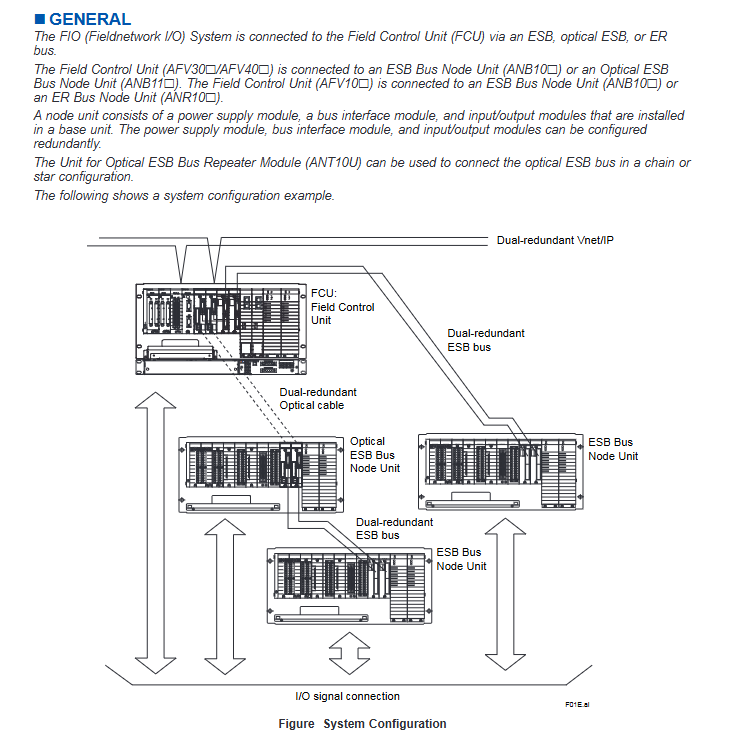
(1) Overall system architecture
The FIO system adopts a three-level architecture of "FCU+node unit+I/O module", which realizes data transmission through three types of buses: ESB/optical ESB/ER, and supports dual redundancy configuration (Vnet/IP bus, communication bus, and module all support redundancy). The typical configuration is as follows:
Top level: Field Control Unit (FCU), responsible for data processing and issuing control instructions;
Middle level: Node unit, serving as the connection hub between FCU and I/O module, including power module and bus interface module;
Bottom layer: I/O module, responsible for the acquisition and output of on-site signals (analog/digital/communication).
(2) Detailed explanation of core hardware components
1. On site Control Unit (FCU)
Model series, type, structure, form, adaptation, bus, key characteristics
AFV10 (AFV10S/AFV10D) Standard 19 inch rack mounted (single redundant S/double redundant D) ESB bus, ER bus basic control function, supports LFS1500 database, and can connect up to 14 node units after expansion
AFV30 (AFV30S/AFV30D) Advanced 19 inch rack mounted (single/double redundant) ESB bus and optical ESB bus require installation of EC401/EC402 coupling module, supporting LFS1700 database, with a maximum of 13 node units after expansion
AFV40 (AFV40S/AFV40D) Enhanced with Cabinet (Single/Double Redundancy) ESB Bus, Optical ESB Bus Built in EC401/EC402 Module, Maximum 11 Node Units Installed in Single Cabinet, Prohibited for Use in Hazardous Areas
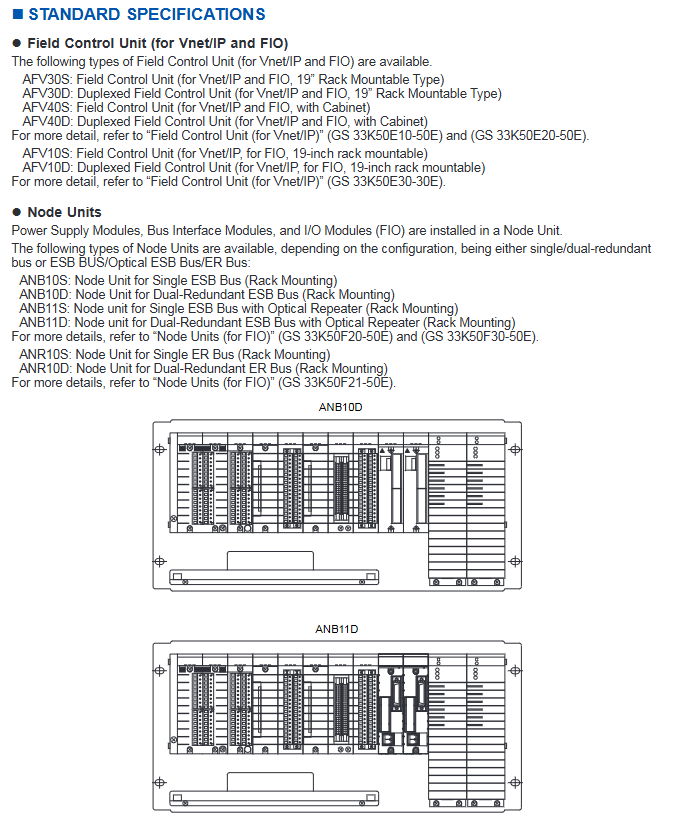
Node units and relay units
Unit type, model, bus type, core function, redundancy support
ESB bus node units ANB10S/ANB10D are connected to the full range of AFV FCUs via the ESB bus, compatible with most I/O modules with single redundancy (S)/dual redundancy (D)
Optical ESB bus node unit ANB11S/ANB11D Optical ESB bus supports long-distance transmission, with built-in optical relay module single redundancy (S)/dual redundancy (D)
The ER bus node units ANR10S/ANR10D are only compatible with AFV10 FCU and support specific I/O module single redundancy (S)/dual redundancy (D)
Optical ESB relay unit ANT10U optical ESB bus extends the transmission distance of optical ESB, supporting chain/star topology and requiring the use of ANT401/ANT411 and other relay modules
Classification and core specifications of I/O modules
I/O modules are divided into 5 categories, supporting various configurations such as isolated/non isolated, explosion-proof/non explosion-proof, etc. The core parameters are as follows:
Module category represents model, channel number, signal type, isolation characteristics, explosion-proof level, temperature range
Analog input module AAI141 16 channel 4-20mA (non isolated) non isolated CSA NI, FM NI 0-60 ℃
Analog output module AAI543 16 channel 4-20mA (isolated) Isolation Type n, Type i 0-60 ℃ (fast response type)
Digital input module ADV151 32 channel 24V DC isolated CSA NI, FM NI 0-60 ℃
Digital output module ADV551 32 channel 24V DC isolation Type n, Type i 0-60 ℃
Communication module ALR111 2-port RS-232C non isolated CSA NI, FM NI 0-50 ℃
Turbomachinery module AGS813 12 channel servo signal isolation -0-50 ℃
Built in isolation barrier module ASI133 8-channel 4-20mA input isolation Type i, FM intrinsic safety 0-60 ℃
(3) Comparison of Bus Communication Specifications
The system supports three types of communication buses: ESB, optical ESB, and ER, with the following differences in core parameters:
Bus type transmission rate transmission medium maximum distance topology structure adaptation FCU redundancy support
ESB bus 128Mbps dedicated cable (YCB301) 10m (EC401) bus type AFV10 /AFV30 /AFV40 supported
Optical ESB bus 128Mbps single-mode fiber (LC interface) 50km (ANT411 relay) bus type/chain/star type AFV30 /AFV40 support
ER bus 10Mbps coaxial cable (YCB141/YCB311) 185m (YCB141) bus type AFV10 supported
Bus connection restrictions (according to FCU and database configuration)
FCU model database configuration ESB/optical ESB node unit upper limit ER node unit upper limit Total node unit upper limit
AFV10 LFS1500 3 3 3
AFV10 LFS1500+LFS1550 9 14 14
AFV30/AFV40 LFS1700 3 - 3
AFV30/AFV40 LFS1700+LFS1750-V1 9 - 9
AFV30/AFV40 LFS1700+LFS1750-V2 13 - 13
Environmental and power specifications
(1) Environmental parameters
Project Standard Scope Extension Options (Partial Modules) Remarks
Working temperature FCU: 0-50 ℃; Node Unit: 0-60 ℃ Node Unit: -20-70 ℃ ER Bus Node Unit - Warm up for 10 minutes to start at 20-0 ℃
Storage temperature -20-60 ℃ -40-85 ℃ Avoid direct sunlight
Relative humidity 5-95% RH (no condensation) 5-95% RH (no condensation) Consistent throughout the entire scene
Temperature change rate working: ± 10 ℃/h; storage: ± 20 ℃/h --
Altitude ≤ 2000m --
Vibration 1-14Hz (0.25mm amplitude); 14-100Hz (2.0m/s ²) - Continuous vibration requirements
Impact transportation: horizontal 49.0m/s ²; Vertical 98.0m/s ² - in packaging state
Corrosion gas ANSI/ISA S71.04 G2 ANSI/ISA S71.04 G3 optional G3 level protection
Static protection contact discharge ≤ 4kV; air discharge ≤ 8kV --
(2) Power parameters
Power type, voltage range, frequency/ripple, key characteristics
AC power supply 100-120V AC ± 10%; 220-240V AC ± 10% 50/60Hz ± 3Hz; Distortion rate ≤ 10%, instantaneous power-off tolerance ≤ 20ms
DC power supply 24V DC ± 10% ripple ≤ 1% p-p-
Grounding requires independent grounding, with a grounding resistance of ≤ 100 Ω - to ensure electromagnetic compatibility and safety
Module signal connection and terminal configuration
(1) Signal connection method
Connection Type Applicable Scenarios Support Modules Key Accessories
The pressure clamp terminal is directly connected to the terminal block of most analog/digital modules in the field equipment, with single redundancy (such as ATA4S) and double redundancy (such as ATA4D)
The dedicated cable is connected through the terminal board and compatible with the ST series module ATK4A adapter and KS series cable (such as KS1/KS2)
MIL connector cable directly connects to module specific analog modules (such as AAI141). Customers provide their own cables and require cable connector covers (ACCC01)
(2) Typical Module Terminal Block Combination Example
Module Model Terminal Block (Single Redundancy) Terminal Block (Double Redundancy) Compatible with Cable Terminal Board
AAI141 (4-20mA input) ATA4S ATA4D KS1 AEA4D
ADV151 (24V DC input) ATB5S ATB5D AKB331 AED5D
ALF111 (FF-H1 communication) ATF9S ATF9S (external wiring redundancy) AKB336 AEF9D
ASI133 (built-in isolation gate input) ATSA3S ATSA3D --
(3) I/O module current consumption
Core module current consumption (5V DC/24V DC):
Module model 5V DC maximum consumption (mA) 24V DC maximum consumption (mA)
AAI141 (analog input) 310 450
ADV151 (digital input) 500-
ADV551 (digital output) 700-
ALR111 (RS-232C communication) 500-
ASI133 (built-in isolation gate input) 150 450
AGP813 (high-speed protection module) 900-
Installation restrictions and compliance requirements
(1) Power capacity limit (module factor sum constraint)
Installation scenario module factor calculation rule upper limit requirements
Node units (non hazardous areas) only count factor B ≤ 100
Node unit (danger zone, ANB10 - E) only counts factor B ≤ 88
Node unit (danger zone, ANB10 - F) only counts factor B ≤ 80
Dual redundant FCU (AFV10D/AFV30D, non hazardous area) factor A ≤ 20; Factor A+B ≤ 65-
Dual redundant FCU (AFV10D/AFV30D, hazardous area) factor A ≤ 5; Factor A+B ≤ 65-
Example of Core Module Factors
Module Model: Single Redundancy Factor A Single Redundancy Factor B Double Redundancy Factor B
AAI141 0 16 16
AAI543 (Standard Response) 0 21 25
AAI543 (Quick Response) 0 21 29
ADV151 0 0 0
ASI133 0 22 33
AGP813 3 0 6
(2) Temperature related installation restrictions
60-70 ℃ environment: Each node can install up to 4 I/O modules, and slots need to be left empty between modules; Two empty slots need to be left for dual redundant I/O modules; Prohibit the installation of AAI543 quick response module;
Specific module temperature constraints: Modules such as AAP149 and ADV157 only support 0-50 ℃; AAI543 quick response type supports 0-60 ℃;
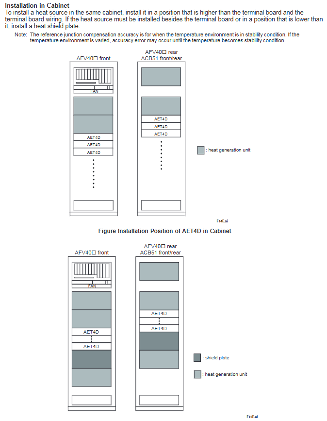
Thermocouple module (AAT141/AST143): It should be kept away from heat sources and blown directly by the airflow. Only specific modules (such as AAT145, ASR133) can be installed adjacent to it. AFV40 cabinet should be installed in slots 3, 4, 5, 7, 8, 9, and 10.
(3) Explosion proof and isolation requirements
The built-in isolation barrier module (such as ASI133, ASD143) needs to maintain a distance of ≥ 50mm from non intrinsic safety modules. The ANB10 node unit needs to install an insulation partition (T9083NA), and the AFV10 /AFV30 needs to install an insulation partition kit (T9083ND);
Explosion proof level adaptation: Type i (intrinsic safety) or Type n (non sparking) modules are preferred for hazardous areas, and ADR541 does not support Type n level;
Wiring specification: The cross-sectional area of the explosion-proof module connecting conductor should be ≤ 1.25mm ², and it should be connected sequentially from the CH1 terminal.
(4) Special restrictions on module installation
Communication and Turbomachinery Module: ALP111 and ALP121 cannot be mixed; AFV10 does not support ALP121; AFV10 can install up to 8 modules such as ALR111/ALR121 (dual redundant 4 pairs);
Bus interface module: EB401 is installed in odd numbered slots with a blank slot on the right side; EC401/EC402 dual redundancy is installed in slots 7 and 8;
Empty slot protection: Dust covers (ADCV01) are required for slots without I/O modules installed;
Dual redundancy configuration: I/O modules need to be installed in adjacent slots (IO1-IO2, IO3-IO4, etc.), and terminal blocks need to use dual redundancy type.
(5) Compliance standards
Safety standards: CSA, CE Marking, EAC Marking (except for ARS series and ADR541 parts);
EMC standards: CE Marking, EAC Marking, RCM, KC Marking (excluding built-in isolation barrier modules);
Explosion proof standard: CSA Non-Incendive、FM Non-Incendive、Type n、Type i(Intrinsic Safety)、FM Intrinsic Safety。
- OMRON
- ABB
- General Electric
- EMERSON
- Honeywell
- HIMA
- ALSTOM
- Rolls-Royce
- MOTOROLA
- Rockwell
- Siemens
- Woodward
- YOKOGAWA
- FOXBORO
- KOLLMORGEN
- MOOG
- KB
- YAMAHA
- BENDER
- TEKTRONIX
- Westinghouse
- AMAT
- AB
- XYCOM
- Yaskawa
- B&R
- Schneider
- KONGSBERG
- NI
- WATLOW
- ProSoft
- SEW
- ADVANCED
- Reliance
- TRICONEX
- METSO
- MAN
- Advantest
- STUDER
- DANAHER MOTION
- Bently
- Galil
- EATON
- MOLEX
- DEIF
- B&W
- ZYGO
- Aerotech
- DANFOSS
- Beijer
- Moxa
- Rexroth
- Johnson
- WAGO
- TOSHIBA
- BMCM
- SMC
- HITACHI
- HIRSCHMANN
- Application field
- XP POWER
- CTI
- TRICON
- STOBER
- Thinklogical
- Horner Automation
- Meggitt
- Fanuc
- Baldor
- SHINKAWA
- Other Brands
- UniOP
- KUKA
- Iba
- Beckhoff
-
 Basler D90 96801 100 PCB Card
 -
 Basler XR2002F Voltage Regulator (110 VAC, 48-480 Hz)
 -
 Basler SR8A-2B14B3A Regulator
 -
 Basler 9561500100 Module
 -
 Basler DECS-400 BE1-11 System
 -
 Basler DECS-100-B15 Excitation Control
 -
 Basler SCP 210 Frequency Controller
 -
 Basler SR4A-2B15B3A Static Voltage Regulator
 -
 Basler BE1-32R Power Relay
 -
 Basler PIA2400-17GM Power Interface Adapter
 -
 Basler MVC 232 Manual Voltage Control Module
 -
 Basler SSR 32-12 Static Voltage Regulator
 -
 Basler 5MW AVR Generator Voltage Regulator
 -
 Basler VR63-4B Voltage Regulator
 -
 Basler DECS-100-A05 AVR for Engine Generator
 -
 Basler DECS-100-B15 Automatic Voltage Regulator
 -
 Basler BE1-32R Directional Power Relay
 -
 Basler BE1-87B Differential Relay
 -
 Basler UFOV 260A Protective Module
 -
 Basler 9-2614-02-100 PCB Rev M
 -
Basler DECS-100-B15 Digital AVR
-
 Basler 9284900103 PS DECS-400N
 -
 Basler D4N3H1U Intertie Protection
 -
 Basler DECS-100-B15 A15 AVR
 -
 Basler KR4F Voltage Regulator
 -
 Basler BE26434 T14 Transformer
 -
 Basler SR8A-2B15B3A Regulator
 -
 Westinghouse 774B472A12 AR Relay
 -
Basler DECS-100-B15 AVR
-
Basler XR2002F Regulator 110V
-
Basler SR125-E Static Regulator
-
 Basler SSR 125-12 Regulator
 -
 Basler MOC2599 Motor Pot
 -
 Basler BE1-DFPR Feeder Relay
 -
 Basler CBS 305 Current Boost
 -
 Basler BE1-25 AutoSync
 -
 Basler MVC 300 Voltage Control
 -
 Basler BE3-25A AutoSync
 -
 Basler KR7FF Static Regulator
 -
 Basler 90-49000-100 Regulator
 -
 Basler 880 kVA Dry Type Transformer Specs
 -
 Basler Electric BE1-25 Sync-Check Relay Specs
 -
 Basler SSR 125-12 Voltage Regulator Specs
 -
 Basler Electric BE1-851 Overcurrent Relay Review
 -
Basler Electric 149D930G02 Control Sub-Assembly
-
 Basler Electric BE1-81O/UT Frequency Relay Specs
 -
 Basler Electric BE1-51/27C Overcurrent Relay
 -
 Basler Electric 149D956G02 Industrial Component
 -
Basler Electric BE1-51A Overcurrent Relay Specs
-
 Basler Electric BE1-40Q Loss of Excitation Relay
 -
 Basler DECS-200 Excitation Control System
 -
 Basler DECS-200 Voltage Regulator 56-277V AC / 125V DC
 -
Basler BE1-87T Transformer Differential Relay
-
 Basler RDP-110-S1 Protection Relay
 -
 Basler BE1-700V Digital Protective Relay
 -
 Basler BE1-951 Overcurrent Protection System
 -
 Basler DECS-300 Digital Excitation Control
 -
 Basler DECS-200 Digital Excitation Control
 -
 Basler DECS-200-1C Excitation Control System
 -
Basler DECS-200-1L Digital Excitation Control
-
 Basler Electric BE1-GPS Generator Protection System
 -
Basler Electric DECS-200-1C Digital Excitation Controller
-
 Basler Electric DECS125-15 Excitation Control with Power Module
 -
 Basler Electric BE1-87G Differential Relay
 -
 Basler Electric BE1-11 Protection System I5A3M2P2N0EA00
 -
Basler Electric DECS-200-1C Excitation Control System
-
Basler Electric BE1-11g Generator Protection Relay
-
Basler Electric DECS 125-15-B2C1 V2.0.9 Excitation Control
-
 Basler Electric BE1-81O/UT3ED1JA7N2F Frequency Relay
 -
Basler Electric BE1-81O/UT3EE1YB7N1F Frequency Relay
-
 Basler Electric DECS-200-1L Digital Excitation Control System
 -
Basler DECS125-15-B2C1 Excitation Control
-
 Basler 9507900205 SSR Retrofit Voltage Regulator
 -
 Basler BE2000E Digital Voltage Regulator
 -
 Basler BE1-GPS Generator Protection System
 -
Basler DECS-250-CN1CN1N Digital Excitation Control
-
 Basler DGC-2020 Genset Controller
 -
 Basler BE1-81O UT3ED1LA7N0F Frequency Relay (Variant)
 -
 Basler BE1-81O UT3EE1YA9S0F Frequency Relay (Variant)
 -
Basler BE1-81O Over/Under Frequency Relay
-
Basler DECS125-15 Digital Excitation Control
-
Basler Electric BE1-951 Overcurrent Protection System
-
 Basler Electric BE1-700V Digital Protective Relay
 -
 Basler Electric APR63-5 Automatic Voltage Regulator
 -
Basler Electric BE1-851 Overcurrent Protection System
-
Basler Electric DECS-250-LN1SN1N Excitation Control
-
 Basler Electric BE1-87T Transformer Differential Relay
 -
Basler Electric DECS-200-1L Excitation Control System
-
 Basler Electric 9310300100 DECS-300 Excitation Control
 -
 Basler Electric SSE-N 125-4.5KW Shunt Exciter Regulator
 -
 Basler Electric DGC-2020HD-5NS1DNSBA Genset Controller
 -
Basler Electric BE1-81-O/UT3EE1JB7N1F Frequency Relay
-
Basler Electric BE1-81T1EE1WA0N1F Frequency Relay
-
 Basler Electric BE1-25M1EA6PN5R1F Sync-Check Relay
 -
 Basler Electric BE1-GPS Generator Protection System
 -
Basler Electric DECS-250-LN1SN1N Excitation Control Rev V
-
 Basler Electric DECS-250-CN2CN1N Excitation Control
 -
Basler Electric BE1-50/51B-207 Overcurrent Relay
-
Basler Electric DECS-300-C0N0 Excitation Control System
-
Basler Electric DECS-200 Digital Excitation Control System
-
Basler Electric DECS-250-LN1CN1N Excitation Unit
-
Basler Electric DECS-250 LN2SA1D Excitation Unit Specs
-
Basler Electric BE1-87T Transformer Relay Review
-
Basler Electric BE1-11 Protection System
-
Basler Electric BE1-GPS100-E4N1H1N Protection System
-
 Allen-Bradley 442G-MABH-R Safety Module
 -
 Beckhoff CX1030-0111 PLC Assembly Profile
 -
 FANUC IC693CPU364 PLC Module
 -
 Orange Denmark Type 200816 220 PLC Specs
 -
 OMRON C200H-SNT31 Sysmac PLC Module
 -
 Allen Bradley 20AB022A3AYNANC0 PowerFlex 70
 -
 OMRON C200HW-PCU01 Position Control Unit
 -
 ABB AO845A-eA Analog Output Module
 -
 OMRON CJ1M-CPU22 CPU Unit
 -
 Allen Bradley 100-E265ED11 Contactor
 -
 Honeywell 51304511-100 Interface Module
 -
 SOLEXY BXF3S0101N0018 Gateway Module
 -
 OMRON CJ2H-CPU65 CPU Unit
 -
 Automation Direct GS2-45P0 AC Drive
 -
 M68-2000 2-Axis Motion CNC Controller
 -
 OMRON CJ1M-CPU11 V3.0 PLC CPU Unit
 -
 OMRON CJ1W-NC413 4-Axis Positioning Controller
 -
 OMRON 3G2A3-PRO16 Programming Console HMI
 -
 Siemens 3VT8440-2AA04-2GA2 Molded Case Circuit Breaker
 -
 Siemens 3RT5045 Contactor Series
 -
 OMRON C200HS-CPU01-E SYSMAC PLC Controller
 -
 OMRON C500-NC103-E Positioning Control Unit
 -
 OMRON CJ1W-TC001 Temperature Control Unit


