
REXROTH Digital axis control HNC100
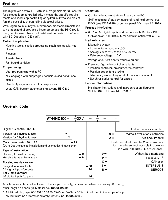
VT-HNC100-1: Single axis version, supports 8 or 24 digital inputs/outputs
VT-HNC100-2: Dual axis version, supports 16 digital inputs/outputs
Both belong to the 2X component series (20-29 series, with unchanged installation and connection dimensions), comply with the EC directive (CE mark), and exhibit excellent anti-interference, mechanical anti vibration and shock resistance, and weather resistance, making them suitable for harsh industrial environments.
REXROTH Digital axis control HNC100
Product Overview
Product positioning and types
VT-HNC100 is a programmable NC controller developed by Bosch Rexroth AG, specifically designed for closed-loop control shafts. It meets the specific requirements of hydraulic drive closed-loop control and can also be used for electric drive control. The products are divided into two main types:
VT-HNC100-1: Single axis version, supports 8 or 24 digital inputs/outputs
VT-HNC100-2: Dual axis version, supports 16 digital inputs/outputs
Both belong to the 2X component series (20-29 series, with unchanged installation and connection dimensions), comply with the EC directive (CE mark), and exhibit excellent anti-interference, mechanical anti vibration and shock resistance, and weather resistance, making them suitable for harsh industrial environments.
Application scenarios
Widely used in the following industrial equipment:
Machine tools, plastic processing machines, special machinery
Presses
Transfer lines
Rail bound vehicles
Core functions and operations
(1) Programming and Operations
Programming method
User programming through PC, using NC language with subroutine technology and conditional jump
Support writing exclusive NC programs for functional sequences
Multiple HNC100 parameters can be set through the local CAN bus
Operations Management
Implementing convenient data management on PC
Quickly modify data through handheld control box BB-3 (reference RE 29798) or control panel BF-1 (reference RE 29794)
Software Configuration Tool - WIN-PED
It needs to be ordered separately or downloaded for free from the official website (material number R900725471, download address: www.boschrexroth. de/hnc100). The functions include:
Convenient dialogue function for online/offline setting of machine tool data
NC editor with syntax check and program compiler
Support the definition of parameters used in NC programs
Dialogue window for setting parameter values online
Multiple options for displaying process data, digital I/O, and flag bits
Record and graphically display up to 4 process variables (with selectable trigger options)
Graphically defining special functions (determined by polygons)
The operating system requirements are: IBM PC or compatible machine, Windows 9x/NT, Intel 80286 and above processor (recommended 80486), at least 8MB RAM (recommended 16MB), 10MB free hard disk space.
(2) Core functions of the controller
Key functions of controller type
Position Controller (PDT1 Controller) - Linear Gain Characteristic Curve, Direction Dependent Gain Adjustment
-The "bending" gain characteristic curve can be modified by NC program to adjust the gain
-Fine positioning, residual voltage principle, zero error compensation
-State feedback, instruction value feedforward
-Limit control output through NC program and support 'position dependent braking'
-2-axis synchronous control
Pressure/Force Controller (PIDT1 Controller) - Component I can be cut in and out through a window
-Differential pressure evaluation function
-Independent scanning rate
Speed controller (PI controller) - I component can be cut in and out through a window
Monitoring Function - Dynamic Follow Error Monitoring
-Travel range limit (electronic limit switch)
-Incremental and SSI encoder disconnection monitoring
-4-20mA output sensor disconnection monitoring
-Reset the 'error free' output and disable the controller in case of malfunction
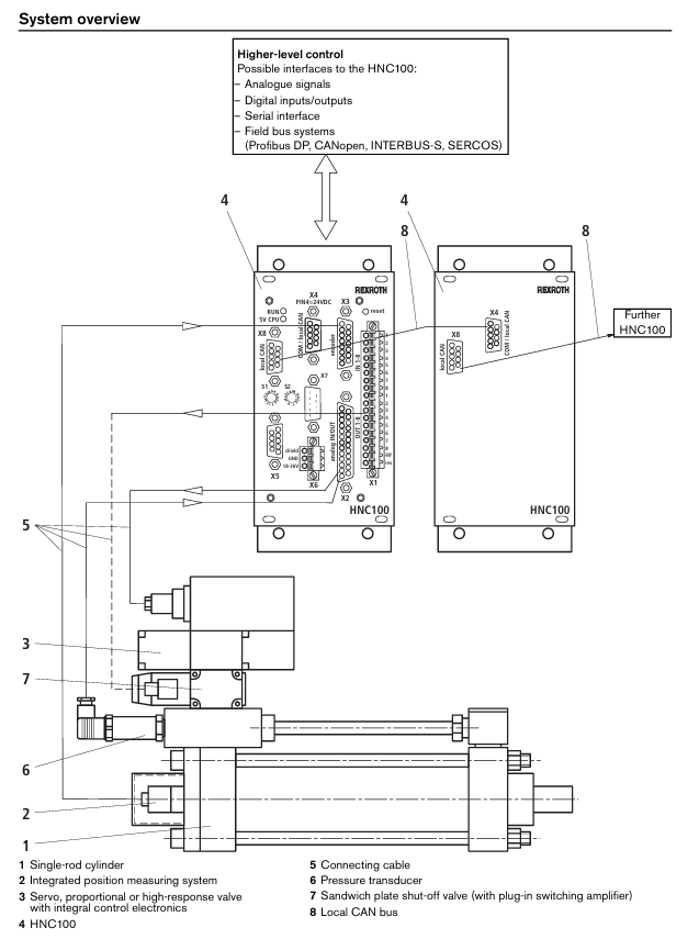
(3) Process interface
Support multiple interface methods for communication with PLC:
Digital input/output: single axis version with 8 or 24 channels, dual axis version with 16 channels
Fieldbus: Profibus DP, CANopen, INTERBUS-S, SERCOS (note: interface cables are not included in the supply scope, 3-meter cables can be ordered separately, other lengths need to be consulted); Profibus DP requires an additional order for plug 6ES7972-0BA20-0XA0, material number R900050152) Analog signal, serial interface
Technical parameters
(1) Basic electrical and hardware parameters
Parameter category specific specifications
Working voltage (U ₀) 18-36 VDC
Power consumption (P_int) 8 W (including connected sensor/actuator power supply)
Processor 16/32-bit MC68376
Storage capacity Flash EPROM: 1 MB; EEPROM:8 KB; RAM (Main Memory): 256 KB
Position sensor power supply U ₀ or+5 VDC ± 5%, maximum 200 mA
The maximum voltage of all input signals is U ₀ -1 V (signal without photoelectric isolation)
(2) Simulate input/output parameters
Type and specification
Analog input - Voltage input (differential): 4-channel, input voltage ± 10V (maximum ± 15V), input resistance 200k Ω± 2%, resolution 5mV, nonlinearity<10mV
-Current input: 4-channel, input current 4-20mA, input resistance 100 Ω± 0.2%, resolution 5 μ A
-Impedance input: 4-channel, input voltage ± 10V, input resistance>10M Ω, resolution 5mV
Analog output - Voltage output: 4 channels, output voltage ± 10V (maximum ± 10.7V), output current ± 10mA, minimum load 1k Ω
-Current output: 2-channel, standardized 4-20mA, non standardized ± 23mA, maximum load 500 Ω
-Residual ripple: ± 60mV (no noise), resolution 1.25mV
(3) Digital and Communication Parameters
Parameter category specific specifications
- OMRON
- ABB
- General Electric
- EMERSON
- Honeywell
- HIMA
- ALSTOM
- Rolls-Royce
- MOTOROLA
- Rockwell
- Siemens
- Woodward
- YOKOGAWA
- FOXBORO
- KOLLMORGEN
- MOOG
- KB
- YAMAHA
- BENDER
- TEKTRONIX
- Westinghouse
- AMAT
- AB
- XYCOM
- Yaskawa
- B&R
- Schneider
- KONGSBERG
- NI
- WATLOW
- ProSoft
- SEW
- ADVANCED
- Reliance
- TRICONEX
- METSO
- MAN
- Advantest
- STUDER
- DANAHER MOTION
- Bently
- Galil
- EATON
- MOLEX
- DEIF
- B&W
- ZYGO
- Aerotech
- DANFOSS
- Beijer
- Moxa
- Rexroth
- Johnson
- WAGO
- TOSHIBA
- BMCM
- SMC
- HITACHI
- HIRSCHMANN
- Application field
- XP POWER
- CTI
- TRICON
- STOBER
- Thinklogical
- Horner Automation
- Meggitt
- Fanuc
- Baldor
- SHINKAWA
- Other Brands
- UniOP
- KUKA
- Iba
- Beckhoff
-
 Basler D90 96801 100 PCB Card
 -
 Basler XR2002F Voltage Regulator (110 VAC, 48-480 Hz)
 -
 Basler SR8A-2B14B3A Regulator
 -
 Basler 9561500100 Module
 -
 Basler DECS-400 BE1-11 System
 -
 Basler DECS-100-B15 Excitation Control
 -
 Basler SCP 210 Frequency Controller
 -
 Basler SR4A-2B15B3A Static Voltage Regulator
 -
 Basler BE1-32R Power Relay
 -
 Basler PIA2400-17GM Power Interface Adapter
 -
 Basler MVC 232 Manual Voltage Control Module
 -
 Basler SSR 32-12 Static Voltage Regulator
 -
 Basler 5MW AVR Generator Voltage Regulator
 -
 Basler VR63-4B Voltage Regulator
 -
 Basler DECS-100-A05 AVR for Engine Generator
 -
 Basler DECS-100-B15 Automatic Voltage Regulator
 -
 Basler BE1-32R Directional Power Relay
 -
 Basler BE1-87B Differential Relay
 -
 Basler UFOV 260A Protective Module
 -
 Basler 9-2614-02-100 PCB Rev M
 -
Basler DECS-100-B15 Digital AVR
-
 Basler 9284900103 PS DECS-400N
 -
 Basler D4N3H1U Intertie Protection
 -
 Basler DECS-100-B15 A15 AVR
 -
 Basler KR4F Voltage Regulator
 -
 Basler BE26434 T14 Transformer
 -
 Basler SR8A-2B15B3A Regulator
 -
 Westinghouse 774B472A12 AR Relay
 -
Basler DECS-100-B15 AVR
-
Basler XR2002F Regulator 110V
-
Basler SR125-E Static Regulator
-
 Basler SSR 125-12 Regulator
 -
 Basler MOC2599 Motor Pot
 -
 Basler BE1-DFPR Feeder Relay
 -
 Basler CBS 305 Current Boost
 -
 Basler BE1-25 AutoSync
 -
 Basler MVC 300 Voltage Control
 -
 Basler BE3-25A AutoSync
 -
 Basler KR7FF Static Regulator
 -
 Basler 90-49000-100 Regulator
 -
 Basler 880 kVA Dry Type Transformer Specs
 -
 Basler Electric BE1-25 Sync-Check Relay Specs
 -
 Basler SSR 125-12 Voltage Regulator Specs
 -
 Basler Electric BE1-851 Overcurrent Relay Review
 -
Basler Electric 149D930G02 Control Sub-Assembly
-
 Basler Electric BE1-81O/UT Frequency Relay Specs
 -
 Basler Electric BE1-51/27C Overcurrent Relay
 -
 Basler Electric 149D956G02 Industrial Component
 -
Basler Electric BE1-51A Overcurrent Relay Specs
-
 Basler Electric BE1-40Q Loss of Excitation Relay
 -
 Basler DECS-200 Excitation Control System
 -
 Basler DECS-200 Voltage Regulator 56-277V AC / 125V DC
 -
Basler BE1-87T Transformer Differential Relay
-
 Basler RDP-110-S1 Protection Relay
 -
 Basler BE1-700V Digital Protective Relay
 -
 Basler BE1-951 Overcurrent Protection System
 -
 Basler DECS-300 Digital Excitation Control
 -
 Basler DECS-200 Digital Excitation Control
 -
 Basler DECS-200-1C Excitation Control System
 -
Basler DECS-200-1L Digital Excitation Control
-
 Basler Electric BE1-GPS Generator Protection System
 -
Basler Electric DECS-200-1C Digital Excitation Controller
-
 Basler Electric DECS125-15 Excitation Control with Power Module
 -
 Basler Electric BE1-87G Differential Relay
 -
 Basler Electric BE1-11 Protection System I5A3M2P2N0EA00
 -
Basler Electric DECS-200-1C Excitation Control System
-
Basler Electric BE1-11g Generator Protection Relay
-
Basler Electric DECS 125-15-B2C1 V2.0.9 Excitation Control
-
 Basler Electric BE1-81O/UT3ED1JA7N2F Frequency Relay
 -
Basler Electric BE1-81O/UT3EE1YB7N1F Frequency Relay
-
 Basler Electric DECS-200-1L Digital Excitation Control System
 -
Basler DECS125-15-B2C1 Excitation Control
-
 Basler 9507900205 SSR Retrofit Voltage Regulator
 -
 Basler BE2000E Digital Voltage Regulator
 -
 Basler BE1-GPS Generator Protection System
 -
Basler DECS-250-CN1CN1N Digital Excitation Control
-
 Basler DGC-2020 Genset Controller
 -
 Basler BE1-81O UT3ED1LA7N0F Frequency Relay (Variant)
 -
 Basler BE1-81O UT3EE1YA9S0F Frequency Relay (Variant)
 -
Basler BE1-81O Over/Under Frequency Relay
-
Basler DECS125-15 Digital Excitation Control
-
Basler Electric BE1-951 Overcurrent Protection System
-
 Basler Electric BE1-700V Digital Protective Relay
 -
 Basler Electric APR63-5 Automatic Voltage Regulator
 -
Basler Electric BE1-851 Overcurrent Protection System
-
Basler Electric DECS-250-LN1SN1N Excitation Control
-
 Basler Electric BE1-87T Transformer Differential Relay
 -
Basler Electric DECS-200-1L Excitation Control System
-
 Basler Electric 9310300100 DECS-300 Excitation Control
 -
 Basler Electric SSE-N 125-4.5KW Shunt Exciter Regulator
 -
 Basler Electric DGC-2020HD-5NS1DNSBA Genset Controller
 -
Basler Electric BE1-81-O/UT3EE1JB7N1F Frequency Relay
-
Basler Electric BE1-81T1EE1WA0N1F Frequency Relay
-
 Basler Electric BE1-25M1EA6PN5R1F Sync-Check Relay
 -
 Basler Electric BE1-GPS Generator Protection System
 -
Basler Electric DECS-250-LN1SN1N Excitation Control Rev V
-
 Basler Electric DECS-250-CN2CN1N Excitation Control
 -
Basler Electric BE1-50/51B-207 Overcurrent Relay
-
Basler Electric DECS-300-C0N0 Excitation Control System
-
Basler Electric DECS-200 Digital Excitation Control System
-
Basler Electric DECS-250-LN1CN1N Excitation Unit
-
Basler Electric DECS-250 LN2SA1D Excitation Unit Specs
-
Basler Electric BE1-87T Transformer Relay Review
-
Basler Electric BE1-11 Protection System
-
Basler Electric BE1-GPS100-E4N1H1N Protection System
-
 Allen-Bradley 442G-MABH-R Safety Module
 -
 Beckhoff CX1030-0111 PLC Assembly Profile
 -
 FANUC IC693CPU364 PLC Module
 -
 Orange Denmark Type 200816 220 PLC Specs
 -
 OMRON C200H-SNT31 Sysmac PLC Module
 -
 Allen Bradley 20AB022A3AYNANC0 PowerFlex 70
 -
 OMRON C200HW-PCU01 Position Control Unit
 -
 ABB AO845A-eA Analog Output Module
 -
 OMRON CJ1M-CPU22 CPU Unit
 -
 Allen Bradley 100-E265ED11 Contactor
 -
 Honeywell 51304511-100 Interface Module
 -
 SOLEXY BXF3S0101N0018 Gateway Module
 -
 OMRON CJ2H-CPU65 CPU Unit
 -
 Automation Direct GS2-45P0 AC Drive
 -
 M68-2000 2-Axis Motion CNC Controller
 -
 OMRON CJ1M-CPU11 V3.0 PLC CPU Unit
 -
 OMRON CJ1W-NC413 4-Axis Positioning Controller
 -
 OMRON 3G2A3-PRO16 Programming Console HMI
 -
 Siemens 3VT8440-2AA04-2GA2 Molded Case Circuit Breaker
 -
 Siemens 3RT5045 Contactor Series
 -
 OMRON C200HS-CPU01-E SYSMAC PLC Controller
 -
 OMRON C500-NC103-E Positioning Control Unit
 -
 OMRON CJ1W-TC001 Temperature Control Unit


